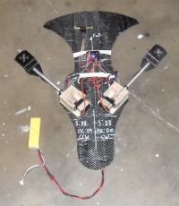
CSU Chico Tilt Rotor Flying Machine, (Airframe and Electronics, 2 of 3).
Patrick, Mon Mar 26 2012, 03:53AMCSU Chico Tilt Rotor Flying Machine, (Airframe and Electronics, 2 of 3.)
Supporting threads:
 CSU Chico Tilt Rotor Flying Machine, (Programming and CPU, 3 of 3).
 PDF's: (soon)
gyro
accerl
mag
stm32's
IR proximity sensors.
U-dar
YouTube:
 Avatar Scorpion Gunship RC - TwinCopter
 Related threads:
Differences between good fiberglass, and good Carbon fiber.

International Aerial Robotics Competition, Mission 6, 2011.

69mm Electric Ducted Fan, 2.8 lbs Static Thrust...

Need help with the STM32F4-Discovery board...

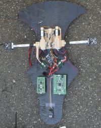
Pics!
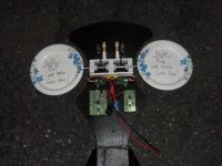
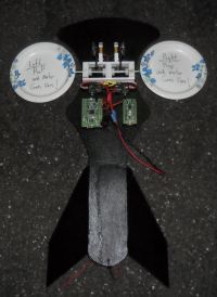
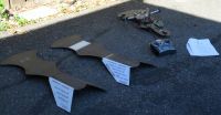
please forgive the paper plates, i needed to show the fan placement, but they're not ready yet.
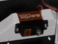
Titanium gear digital servo.

A similar metal gear servo.
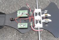
Its got guts!!!

37 inches long in this pic. No motors or rotors yet.
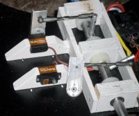
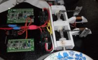
Re: CSU Chico Tilt Rotor Flying Machine, (Airframe and Electronics, 2 of 3).
Carbon_Rod, Mon Mar 26 2012, 05:44AM
Do you plan to cut holes in the air frame to fit the battery and servos?
Note, loose cable ties and Styrofoam often help PCB survive torsional strains during impact.
It would be wise to anchor the main ESC battery connection cable to the air frame so it will pull-free from the battery during impact....
The Oak and the Reed, Jean de la Fontaine (1621-1695)
The Oak spoke one day to the Reed
"You have good reason to complain;
A Wren for you is a load indeed;
The smallest wind bends you in twain.
You are forced to bend your head;
While my crown faces the plains
And not content to block the sun
Braves the efforts of the rains.
What for you is a North Wind is for me but a zephyr.
Were you to grow within my shade
Which covers the whole neighbourhood
You'd have no reason to be afraid
For I would keep you from the storm.
Instead you usually grow
In places humid, where the winds doth blow.
Nature to thee hath been unkind."
"Your compassion", replied the Reed
"Shows a noble character indeed;
But do not worry: the winds for me
Are much less dangerous than for thee;
I bend, not break. You have 'til now
Resisted their great force unbowed,
But beware.
As he said these very words
A violent angry storm arose.
The tree held strong; the Reed he bent.
The wind redoubled and did not relent,
Until finally it uprooted the poor Oak
Whose head had been in the heavens
And roots among the dead folk.
Carbon_Rod, Mon Mar 26 2012, 05:44AM
Do you plan to cut holes in the air frame to fit the battery and servos?
Note, loose cable ties and Styrofoam often help PCB survive torsional strains during impact.
It would be wise to anchor the main ESC battery connection cable to the air frame so it will pull-free from the battery during impact....

The Oak and the Reed, Jean de la Fontaine (1621-1695)
The Oak spoke one day to the Reed
"You have good reason to complain;
A Wren for you is a load indeed;
The smallest wind bends you in twain.
You are forced to bend your head;
While my crown faces the plains
And not content to block the sun
Braves the efforts of the rains.
What for you is a North Wind is for me but a zephyr.
Were you to grow within my shade
Which covers the whole neighbourhood
You'd have no reason to be afraid
For I would keep you from the storm.
Instead you usually grow
In places humid, where the winds doth blow.
Nature to thee hath been unkind."
"Your compassion", replied the Reed
"Shows a noble character indeed;
But do not worry: the winds for me
Are much less dangerous than for thee;
I bend, not break. You have 'til now
Resisted their great force unbowed,
But beware.
As he said these very words
A violent angry storm arose.
The tree held strong; the Reed he bent.
The wind redoubled and did not relent,
Until finally it uprooted the poor Oak
Whose head had been in the heavens
And roots among the dead folk.
Re: CSU Chico Tilt Rotor Flying Machine, (Airframe and Electronics, 2 of 3).
Patrick, Mon Mar 26 2012, 06:19AM
Yep, ill be using holes, and a battery tray to secure stuff. i would rather bend something than have it break off.
Patrick, Mon Mar 26 2012, 06:19AM
Yep, ill be using holes, and a battery tray to secure stuff. i would rather bend something than have it break off.
Re: CSU Chico Tilt Rotor Flying Machine, (Airframe and Electronics, 2 of 3).
Dago, Mon Mar 26 2012, 08:13AM
Heh that looks neat. Kinda like a segway except it flies.
Dago, Mon Mar 26 2012, 08:13AM
Heh that looks neat. Kinda like a segway except it flies.
Re: CSU Chico Tilt Rotor Flying Machine, (Airframe and Electronics, 2 of 3).
Steve Conner, Mon Mar 26 2012, 08:29AM
Maybe I'm missing something, but it looks like the centre of gravity will be a long way away from the centre of lift, especially once you've added the battery pack.

In the above picture of a Boeing Osprey, the rotors are roughly in the middle of the aircraft.
Steve Conner, Mon Mar 26 2012, 08:29AM
Maybe I'm missing something, but it looks like the centre of gravity will be a long way away from the centre of lift, especially once you've added the battery pack.

In the above picture of a Boeing Osprey, the rotors are roughly in the middle of the aircraft.
Re: CSU Chico Tilt Rotor Flying Machine, (Airframe and Electronics, 2 of 3).
Patrick, Mon Mar 26 2012, 02:00PM
Patrick, Mon Mar 26 2012, 02:00PM
Steve Conner wrote ...
Maybe I'm missing something, but it looks like the centre of gravity will be a long way away from the centre of lift, especially once you've added the battery pack.

In the above picture of a Boeing Osprey, the rotors are roughly in the middle of the aircraft.
my CG, CL, and CP will all be approximately centered in between the rotors (as in the V-22), the tail only looks heavy its pretty light, and the sensors (MS kinnect and U-dar) are pretty heavy they go in front (with the battery). so it all balances out. its all very Zen.Maybe I'm missing something, but it looks like the centre of gravity will be a long way away from the centre of lift, especially once you've added the battery pack.

In the above picture of a Boeing Osprey, the rotors are roughly in the middle of the aircraft.
Re: CSU Chico Tilt Rotor Flying Machine, (Airframe and Electronics, 2 of 3).
Patrick, Wed Mar 28 2012, 06:52AM
Airframe whieghs 631 grams. (too much!)
servo and torque tube arrangement wheighs 272 g.
ESC's w/wire wheigh 142 g
11.1v 2200mAh battery wheighs 190 g.
circuit boards 65 g.
-----------------------------------------------
total mass is about 1.490 Kg's.
i need to lighten the airframe by about 300 grams.
Re: CSU Chico Tilt Rotor Flying Machine, (Airframe and Electronics, 2 of 3).
Steve Conner, Wed Mar 28 2012, 09:19AM
Well, what is the tail there for? It can't be for aerodynamic stability. If your design needed the tail for stability, it would be unstable in hover mode, when there's no airflow over it. So I suggest chopping it off.
The Osprey (and its RC model version from Rotormast) needs helicopter-style rotors with cyclic pitch control. These can generate a pitching moment to control the vehicle in the pitch axis. A quadrotor does that by having rotors fore and aft of the CG.
You don't seem to have any active control in the pitch axis at all. No matter how you tilt your rotors, the thrust vector will always pass through the CG and there'll be no pitching moment.
Steve Conner, Wed Mar 28 2012, 09:19AM
Well, what is the tail there for? It can't be for aerodynamic stability. If your design needed the tail for stability, it would be unstable in hover mode, when there's no airflow over it. So I suggest chopping it off.

The Osprey (and its RC model version from Rotormast) needs helicopter-style rotors with cyclic pitch control. These can generate a pitching moment to control the vehicle in the pitch axis. A quadrotor does that by having rotors fore and aft of the CG.
You don't seem to have any active control in the pitch axis at all. No matter how you tilt your rotors, the thrust vector will always pass through the CG and there'll be no pitching moment.
Re: CSU Chico Tilt Rotor Flying Machine, (Airframe and Electronics, 2 of 3).
Patrick, Wed Mar 28 2012, 01:51PM
As for the pitch and CG comment, i see no problem, i want the sensor plane (the airframe) to remain flat even when the rotors are full forward or aft. the last thing i want is my sensor plane rotating as im trying to update the SLAM model.
Patrick, Wed Mar 28 2012, 01:51PM
Steve Conner wrote ...
Well, what is the tail there for? It can't be for aerodynamic stability. If your design needed the tail for stability, it would be unstable in hover mode, when there's no airflow over it. So I suggest chopping it off.
The Osprey (and its RC model version from Rotormast) needs helicopter-style rotors with cyclic pitch control. These can generate a pitching moment to control the vehicle in the pitch axis. A quadrotor does that by having rotors fore and aft of the CG.
You don't seem to have any active control in the pitch axis at all. No matter how you tilt your rotors, the thrust vector will always pass through the CG and there'll be no pitching moment. If you look at the you tube clip link above youll see his "twin copter " remain quite usable even when manuevered flat. pitching and rolling seemed to cause problems in narrow office hallways when i was at IARC 2011. for that reason i wanted to use yaw and tilt instead.
yepp as soon as i dont need the magnetometer ill be chopping the tail off (it was mostly for crash protection, and to look spiffy), also i used to much epoxy on one side on the FG. my gaol is to get the total airframe down to 250 grams or less.Well, what is the tail there for? It can't be for aerodynamic stability. If your design needed the tail for stability, it would be unstable in hover mode, when there's no airflow over it. So I suggest chopping it off.

The Osprey (and its RC model version from Rotormast) needs helicopter-style rotors with cyclic pitch control. These can generate a pitching moment to control the vehicle in the pitch axis. A quadrotor does that by having rotors fore and aft of the CG.
You don't seem to have any active control in the pitch axis at all. No matter how you tilt your rotors, the thrust vector will always pass through the CG and there'll be no pitching moment. If you look at the you tube clip link above youll see his "twin copter " remain quite usable even when manuevered flat. pitching and rolling seemed to cause problems in narrow office hallways when i was at IARC 2011. for that reason i wanted to use yaw and tilt instead.
As for the pitch and CG comment, i see no problem, i want the sensor plane (the airframe) to remain flat even when the rotors are full forward or aft. the last thing i want is my sensor plane rotating as im trying to update the SLAM model.
Re: CSU Chico Tilt Rotor Flying Machine, (Airframe and Electronics, 2 of 3).
Steve Conner, Thu Mar 29 2012, 07:33AM
OK, but my point is: Let's say your vehicle acquires a pitch error. Maybe a gust of wind tips the nose up. How will the control system correct it?
Steve Conner, Thu Mar 29 2012, 07:33AM
OK, but my point is: Let's say your vehicle acquires a pitch error. Maybe a gust of wind tips the nose up. How will the control system correct it?
Re: CSU Chico Tilt Rotor Flying Machine, (Airframe and Electronics, 2 of 3).
Patrick, Thu Mar 29 2012, 09:02PM
Patrick, Thu Mar 29 2012, 09:02PM
Steve Conner wrote ...
OK, but my point is: Let's say your vehicle acquires a pitch error. Maybe a gust of wind tips the nose up. How will the control system correct it?
I fail to see why tilting both rotor fans to counter the unwannted pitch up, wont work. isnt this what the v-22 does? or does the V-22 use variable pitch to increase effective collective.OK, but my point is: Let's say your vehicle acquires a pitch error. Maybe a gust of wind tips the nose up. How will the control system correct it?
Re: CSU Chico Tilt Rotor Flying Machine, (Airframe and Electronics, 2 of 3).
Steve Conner, Fri Mar 30 2012, 07:19AM
Well, the problem is: If you made the thrust vector of the fans pass through the centre of gravity, then there won't be any pitching moment no matter how you tilt them. And if you didn't, then you'll have other serious stability problems. Either it won't hover or it won't convert.
I don't know for sure, but I guess the V22's rotors both have cyclic pitch control like a helicopter. The blades vary pitch in time with the rotation, allowing the thrust vector to be placed anywhere you want.
For example, if a helicopter wants to move forward: The cyclic pitch control causes the rear half of the rotor to produce more thrust than the front. This moves the thrust vector aft of the CG, causing the nose to pitch down. The thrust vector now has a component rearwards as well as downwards, and the chopper moves forward.
A multicopter works in exactly the same way, modulating power to its four small rotors to move the thrust vector around as required. Except with only two fans, you can't move it fore and aft.
Re: CSU Chico Tilt Rotor Flying Machine, (Airframe and Electronics, 2 of 3).
Electroholic, Fri Mar 30 2012, 01:03PM
I think if the CoG hangs below the tilting axis, then everything works.
Electroholic, Fri Mar 30 2012, 01:03PM
I think if the CoG hangs below the tilting axis, then everything works.
Re: CSU Chico Tilt Rotor Flying Machine, (Airframe and Electronics, 2 of 3).
Patrick, Fri Mar 30 2012, 03:44PM
Patrick, Fri Mar 30 2012, 03:44PM
Electroholic wrote ...
I think if the CoG hangs below the tilting axis, then everything works.
yeah i think so, then its like a pendulum, and i think it becomes a first order stability problem. I think. I noticed a slight dihedral on the kkmulticopter's fans in that video. That (and having the CoG low) should give some restoring force to large scale stability (favoring controlability) , while still allowing small signal instability (Still allowing maneuverability).I think if the CoG hangs below the tilting axis, then everything works.
Re: CSU Chico Tilt Rotor Flying Machine, (Airframe and Electronics, 2 of 3).
Patrick, Mon Apr 16 2012, 10:47PM
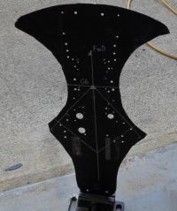
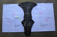
ok CF and GF are cut out and curing, progress so far:

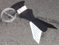
Seen here the dry layers,
3 layers of FG, plain weave, 73 grams dry. Quasiisotopic, should be about 0.030" thick.
5 layers of CF, 2x2 twill weave, 156 grams dry. Quasiisiotropic, should be about .055" thick.
total dry wheight is 229 grams. untrimmed.
Now we see if im talented enuff to screw it all up by adding to much epoxy!
Patrick, Mon Apr 16 2012, 10:47PM
ok CF and GF are cut out and curing, progress so far:

Seen here the dry layers,
3 layers of FG, plain weave, 73 grams dry. Quasiisotopic, should be about 0.030" thick.
5 layers of CF, 2x2 twill weave, 156 grams dry. Quasiisiotropic, should be about .055" thick.
total dry wheight is 229 grams. untrimmed.
Now we see if im talented enuff to screw it all up by adding to much epoxy!
Re: CSU Chico Tilt Rotor Flying Machine, (Airframe and Electronics, 2 of 3).
Patrick, Wed Apr 18 2012, 03:52AM
it weighs in at 400 grams, + a few mods im adding, but subtracting their weight from my other budget mass items.so its all going well. Its super strong and light. only a few pultruded peices and balsa need to be added.
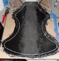
Seen here curing, then it will be sheared down to the white line. Next time ill use 4 layers of CF instead of 5, and then embed the balsa between two layer of two CF, still being quasiisotropic.What you see is the Gen 2 airframe.
Patrick, Wed Apr 18 2012, 03:52AM
it weighs in at 400 grams, + a few mods im adding, but subtracting their weight from my other budget mass items.so its all going well. Its super strong and light. only a few pultruded peices and balsa need to be added.

Seen here curing, then it will be sheared down to the white line. Next time ill use 4 layers of CF instead of 5, and then embed the balsa between two layer of two CF, still being quasiisotropic.What you see is the Gen 2 airframe.
Re: CSU Chico Tilt Rotor Flying Machine, (Airframe and Electronics, 2 of 3).
Patrick, Mon Apr 23 2012, 11:06PM
Ive got this forum posting. which raises the issues already discussed on our threads here.
 tilt rotor, RC forums.
Patrick, Mon Apr 23 2012, 11:06PM
Ive got this forum posting. which raises the issues already discussed on our threads here.
 tilt rotor, RC forums.
Re: CSU Chico Tilt Rotor Flying Machine, (Airframe and Electronics, 2 of 3).
Patrick, Sun May 06 2012, 06:11AM
Weights:
MS Kinect : 144 g
Airframe w/o Tail : 197 g
4 cell lipo: 250 g
Left Wing : 320 g
Right wing : 320 g
main boards : 60 g
ESC's w/ reciever : 170 g
Gyros, accel's : 40 g
servo tray : 120 g
------------------------------
total mass : 1,621 g
Patrick, Sun May 06 2012, 06:11AM
Weights:
MS Kinect : 144 g
Airframe w/o Tail : 197 g
4 cell lipo: 250 g
Left Wing : 320 g
Right wing : 320 g
main boards : 60 g
ESC's w/ reciever : 170 g
Gyros, accel's : 40 g
servo tray : 120 g
------------------------------
total mass : 1,621 g
Re: CSU Chico Tilt Rotor Flying Machine, (Airframe and Electronics, 2 of 3).
Patrick, Tue Jun 12 2012, 10:20PM
IT WORKS!!!
it does fly, however, its unstable in the pitch axis. (As someone predicted [Steve Connor]) i will try to increase the vertical moment arm from 1.2 inches, to about 3 inches. Hopefully that will give gravity more influence on the pitch.
i would like to be able to calculate things out, instead of guessing. But at the moment the measurements, math, and physics elude me...
I have video and many pics, but ive got to edit it all down to reasonable file types and sizes...more posts to come!


Re: CSU Chico Tilt Rotor Flying Machine, (Airframe and Electronics, 2 of 3).
AndrewM, Wed Jun 13 2012, 01:57AM
I think you are still failing to understand Steve's comment.
Have you tried drawing a force diagram? I am interested to see if you can locate the restoring moment you assume exists.
AndrewM, Wed Jun 13 2012, 01:57AM
Patrick wrote ...
it does fly, however, its unstable in the pitch axis. (As someone predicted [Steve Connor]) i will try to increase the vertical moment arm from 1.2 inches, to about 3 inches. Hopefully that will give gravity more influence on the pitch.
it does fly, however, its unstable in the pitch axis. (As someone predicted [Steve Connor]) i will try to increase the vertical moment arm from 1.2 inches, to about 3 inches. Hopefully that will give gravity more influence on the pitch.
I think you are still failing to understand Steve's comment.
Have you tried drawing a force diagram? I am interested to see if you can locate the restoring moment you assume exists.
Re: CSU Chico Tilt Rotor Flying Machine, (Airframe and Electronics, 2 of 3).
Patrick, Wed Jun 13 2012, 03:01AM
I realize i maynot have a full grasp on the statics or dynamics at hand, but lengthening the vertical moment arm did have a profound efffect on pitch and stability... it not perfect and 3 inches, but its flyable and manageble..
ill will draw a free body diagram as soon as i figure it out, but i want some evaluation from others on the situation.
im totally exhausted, ready for bed...
Patrick, Wed Jun 13 2012, 03:01AM
AndrewM wrote ...
I think you are still failing to understand Steve's comment.
Have you tried drawing a force diagram? I am interested to see if you can locate the restoring moment you assume exists.
I think you are still failing to understand Steve's comment.
Have you tried drawing a force diagram? I am interested to see if you can locate the restoring moment you assume exists.
I realize i maynot have a full grasp on the statics or dynamics at hand, but lengthening the vertical moment arm did have a profound efffect on pitch and stability... it not perfect and 3 inches, but its flyable and manageble..
ill will draw a free body diagram as soon as i figure it out, but i want some evaluation from others on the situation.
im totally exhausted, ready for bed...
Re: CSU Chico Tilt Rotor Flying Machine, (Airframe and Electronics, 2 of 3).
AndrewM, Wed Jun 13 2012, 04:05AM
Well I'll just give you the answer - increasing the arm length increased your moment of inertia (by a factor of 4) so your instability just progressed 4x slower. But there is no possible "pendulum" effect in your system.
AndrewM, Wed Jun 13 2012, 04:05AM
Patrick wrote ...
I realize i maynot have a full grasp on the statics or dynamics at hand, but lengthening the vertical moment arm did have a profound efffect on pitch and stability... it not perfect and 3 inches, but its flyable and manageble..
ill will draw a free body diagram as soon as i figure it out, but i want some evaluation from others on the situation.
im totally exhausted, ready for bed...
AndrewM wrote ...
I think you are still failing to understand Steve's comment.
Have you tried drawing a force diagram? I am interested to see if you can locate the restoring moment you assume exists.
I think you are still failing to understand Steve's comment.
Have you tried drawing a force diagram? I am interested to see if you can locate the restoring moment you assume exists.
I realize i maynot have a full grasp on the statics or dynamics at hand, but lengthening the vertical moment arm did have a profound efffect on pitch and stability... it not perfect and 3 inches, but its flyable and manageble..
ill will draw a free body diagram as soon as i figure it out, but i want some evaluation from others on the situation.
im totally exhausted, ready for bed...
Well I'll just give you the answer - increasing the arm length increased your moment of inertia (by a factor of 4) so your instability just progressed 4x slower. But there is no possible "pendulum" effect in your system.
Re: CSU Chico Tilt Rotor Flying Machine, (Airframe and Electronics, 2 of 3).
Patrick, Wed Jun 13 2012, 04:09AM
after all it can be made to work...
Patrick, Wed Jun 13 2012, 04:09AM
AndrewM wrote ...
Well I'll just give you the answer - increasing the arm length increased your moment of inertia (by a factor of 4) so your instability just progressed 4x slower. But there is no possible "pendulum" effect in your system.
ok, but that gives my gyros and PID loops time to put the commands on the servos, and gives the mechanical train time to alter the forces, right?Well I'll just give you the answer - increasing the arm length increased your moment of inertia (by a factor of 4) so your instability just progressed 4x slower. But there is no possible "pendulum" effect in your system.
after all it can be made to work...

Re: CSU Chico Tilt Rotor Flying Machine, (Airframe and Electronics, 2 of 3).
AndrewM, Wed Jun 13 2012, 05:27AM
Absolutely, lots of the flying toys you see now are statically unstable. Active control makes short work of the issue provided you have enough inertia to give it time to react.
AndrewM, Wed Jun 13 2012, 05:27AM
Absolutely, lots of the flying toys you see now are statically unstable. Active control makes short work of the issue provided you have enough inertia to give it time to react.
Re: CSU Chico Tilt Rotor Flying Machine, (Airframe and Electronics, 2 of 3).
Patrick, Wed Jun 13 2012, 06:16AM
Ok so i was wrong about the reasoning (the pendulum) but i was right that increasing the distance bewtween the CL and CG that the time of instability is longer? right?
Patrick, Wed Jun 13 2012, 06:16AM
Ok so i was wrong about the reasoning (the pendulum) but i was right that increasing the distance bewtween the CL and CG that the time of instability is longer? right?
Re: CSU Chico Tilt Rotor Flying Machine, (Airframe and Electronics, 2 of 3).
Steve Conner, Wed Jun 13 2012, 06:19AM
Well, congrats on getting it to fly!
Steve Conner, Wed Jun 13 2012, 06:19AM
Well, congrats on getting it to fly!

Re: CSU Chico Tilt Rotor Flying Machine, (Airframe and Electronics, 2 of 3).
Patrick, Wed Jun 13 2012, 06:38AM
Patrick, Wed Jun 13 2012, 06:38AM
Steve Conner wrote ...
Well, congrats on getting it to fly!
yeah and as unstable as it is, we only broke one of the cheap servos... so now its will soon be time for the Savox servos and good 11" props! i just need to make it more stable.Well, congrats on getting it to fly!

Re: CSU Chico Tilt Rotor Flying Machine, (Airframe and Electronics, 2 of 3).
Carbon_Rod, Wed Jun 13 2012, 08:32AM
Note attaching a balanced wooden stick on a hinge to the airframe with string will provide a "safe" platform for calibration (or finding cg). Without this simple rig people tend to chew through more props etc.
Out of all the sensors, you will likely find a good 3-axis compass provides cleaner data.
However, large metal beams/cars will cause interference (most GPS units also suffer precision loss in urban settings).
Cheers,
Re: CSU Chico Tilt Rotor Flying Machine, (Airframe and Electronics, 2 of 3).
AndrewM, Wed Jun 13 2012, 02:38PM
Yep.
This idea also reminded me - you might consider attaching a number of 4' long wooden sticks to your models primary axes. These will greatly increase your moments of inertia while adding fairly little mass. It will be much easier to fly and tune.
An example is these popular coaxial helicopters:

There is, in fact, nothing inside that fail boom; its just a thin plastic shell. However its not purely decorative; without that boom it is completely unflyable as the gyro and control loop cannot damp the oscillations.
AndrewM, Wed Jun 13 2012, 02:38PM
Patrick wrote ...
Ok so i was wrong about the reasoning (the pendulum) but i was right that increasing the distance bewtween the CL and CG that the time of instability is longer? right?
Ok so i was wrong about the reasoning (the pendulum) but i was right that increasing the distance bewtween the CL and CG that the time of instability is longer? right?
Yep.
Carbon_Rod wrote ...
Note attaching a balanced wooden stick on a hinge to the airframe with string will provide a "safe" platform for calibration (or finding cg). Without this simple rig people tend to chew through more props etc.
Note attaching a balanced wooden stick on a hinge to the airframe with string will provide a "safe" platform for calibration (or finding cg). Without this simple rig people tend to chew through more props etc.
This idea also reminded me - you might consider attaching a number of 4' long wooden sticks to your models primary axes. These will greatly increase your moments of inertia while adding fairly little mass. It will be much easier to fly and tune.
An example is these popular coaxial helicopters:

There is, in fact, nothing inside that fail boom; its just a thin plastic shell. However its not purely decorative; without that boom it is completely unflyable as the gyro and control loop cannot damp the oscillations.
Re: CSU Chico Tilt Rotor Flying Machine, (Airframe and Electronics, 2 of 3).
Josh Campbell, Wed Jun 13 2012, 03:45PM
Can't wait to see some videos of this design in action! (Maybe YouTube so file size would not be an issue...) Congrats on getting it to fly. :)
Josh Campbell, Wed Jun 13 2012, 03:45PM
Can't wait to see some videos of this design in action! (Maybe YouTube so file size would not be an issue...) Congrats on getting it to fly. :)
Re: CSU Chico Tilt Rotor Flying Machine, (Airframe and Electronics, 2 of 3).
Patrick, Wed Jun 13 2012, 05:41PM
thats a great idea, ill do that and report back!
EDIT: ill only put one rod on the roll axis, thats the only axis thats really problematic.
EDIT: It worked... Duh! now i see what steve and andrewM meant, when i lifted the CL above the CG i was creating a vertical pseudo-rod, which helped the pitch some what. As for roll, the rod worked perfectly, even the high freq oscillations in RPM are gone. it's like flying a wholly different machine now!!! Both my ace pilot Corey Koehler and I can fly it...he better than I, but with accerlometers i can definatly program a waypoint and computer pilot, and then generate a SLAM model in real time.
AI flight and IARC 2012 are now within my grasp.
Patrick, Wed Jun 13 2012, 05:41PM
AndrewM wrote ...
This idea also reminded me - you might consider attaching a number of 4' long wooden sticks to your models primary axes. These will greatly increase your moments of inertia while adding fairly little mass. It will be much easier to fly and tune.
An example is these popular coaxial helicopters:

There is, in fact, nothing inside that fail boom; its just a thin plastic shell. However its not purely decorative; without that boom it is completely unflyable as the gyro and control loop cannot damp the oscillations.
This idea also reminded me - you might consider attaching a number of 4' long wooden sticks to your models primary axes. These will greatly increase your moments of inertia while adding fairly little mass. It will be much easier to fly and tune.
An example is these popular coaxial helicopters:

There is, in fact, nothing inside that fail boom; its just a thin plastic shell. However its not purely decorative; without that boom it is completely unflyable as the gyro and control loop cannot damp the oscillations.
thats a great idea, ill do that and report back!
EDIT: ill only put one rod on the roll axis, thats the only axis thats really problematic.
EDIT: It worked... Duh! now i see what steve and andrewM meant, when i lifted the CL above the CG i was creating a vertical pseudo-rod, which helped the pitch some what. As for roll, the rod worked perfectly, even the high freq oscillations in RPM are gone. it's like flying a wholly different machine now!!! Both my ace pilot Corey Koehler and I can fly it...he better than I, but with accerlometers i can definatly program a waypoint and computer pilot, and then generate a SLAM model in real time.
AI flight and IARC 2012 are now within my grasp.
Re: CSU Chico Tilt Rotor Flying Machine, (Airframe and Electronics, 2 of 3).
Patrick, Thu Jun 14 2012, 03:33PM
Ok here are the modified pics of the airframe...
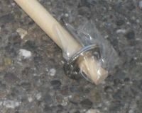
48" long wood rod with steel washers.

Torque tube and Power 10 motor.

Servo and Fan section.
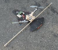
All up machine.
Im still trying to figure out video, so give me awhile. I dont want to kill the sites storage...
Patrick, Thu Jun 14 2012, 03:33PM
Ok here are the modified pics of the airframe...

48" long wood rod with steel washers.

Torque tube and Power 10 motor.

Servo and Fan section.

All up machine.
Im still trying to figure out video, so give me awhile. I dont want to kill the sites storage...
Re: CSU Chico Tilt Rotor Flying Machine, (Airframe and Electronics, 2 of 3).
Steve Conner, Thu Jun 14 2012, 09:33PM
I think the easiest way to post video on here is: upload it to noobtube, make it unlisted so regular Youtube users can't view or comment on it, and allow embedding. Then use the YouTube button in the forum editor to add a link to it, and the video will appear right in the thread.
Re: CSU Chico Tilt Rotor Flying Machine, (Airframe and Electronics, 2 of 3).
Patrick, Fri Jun 15 2012, 06:35AM
Im still trying to figure out video clips so please excuse the breif lame clip below, ill also trying to get a YouToob channel up soon.
CSU Chico Flight Club, Tilt Rotor UAV for IARC 2012.
Description: "Tilt Rotor UAV Drone Test, CSU Chico Flight Club. Flight test conducted by Corey Koehler (A Main Hobbies.com) and Patrick Coleman (EE, CSU Chico), seen in the above clip is the dreaded roll oscillation. This problem has since been solved."
This clip shows the rapid oscillations in the roll axis (left and right tweaking out), then we land it, as of now the rod suggested by AndrewM, has solved this problem entirely.
EDIT: I think this is my YouTube channel, is it?
I dont know how to put text bubbles pointing to places in the video, which for tecnichal demonstrations is kind of important.
Patrick, Fri Jun 15 2012, 06:35AM
Im still trying to figure out video clips so please excuse the breif lame clip below, ill also trying to get a YouToob channel up soon.
CSU Chico Flight Club, Tilt Rotor UAV for IARC 2012.
Description: "Tilt Rotor UAV Drone Test, CSU Chico Flight Club. Flight test conducted by Corey Koehler (A Main Hobbies.com) and Patrick Coleman (EE, CSU Chico), seen in the above clip is the dreaded roll oscillation. This problem has since been solved."
This clip shows the rapid oscillations in the roll axis (left and right tweaking out), then we land it, as of now the rod suggested by AndrewM, has solved this problem entirely.
EDIT: I think this is my YouTube channel, is it?

I dont know how to put text bubbles pointing to places in the video, which for tecnichal demonstrations is kind of important.
Re: CSU Chico Tilt Rotor Flying Machine, (Airframe and Electronics, 2 of 3).
Patrick, Sat Jun 16 2012, 04:58AM
New pics of servo horns...
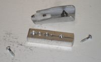
Old horn on top, new horn being made on bottom.
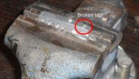
Broke a tap, consequently i have started drinking tonight...
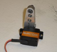
Notice the recessed nut hole for the ball stud.
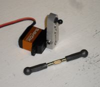
Ball socket turnbuckle, made from hardened titanium, 2.350 inches long.
Patrick, Sat Jun 16 2012, 04:58AM
New pics of servo horns...

Old horn on top, new horn being made on bottom.

Broke a tap, consequently i have started drinking tonight...

Notice the recessed nut hole for the ball stud.

Ball socket turnbuckle, made from hardened titanium, 2.350 inches long.
Re: CSU Chico Tilt Rotor Flying Machine, (Airframe and Electronics, 2 of 3).
Patrick, Tue Jun 26 2012, 01:50AM
oops! crashed it!!
it works well, CG, CR, CL have all been balanced and tuned to the point where it holds a hover, however its still difficult for me to fly. And i crashed it in, broke a titanium gear. Anyway i still need to generate a velocity PID controller to operate from data provided from the 9 DOF gyro-mag-accel MEMS IMU....
Re: CSU Chico Tilt Rotor Flying Machine, (Airframe and Electronics, 2 of 3).
Patrick, Wed Jun 27 2012, 02:06AM
Ok having evaluated the recent crash and damage, i believe it is vulnerable to "pitch tip-stalling" . however i dont know what to do about it (other than reducing the angle once it approaches critical). Need input please.
Patrick, Wed Jun 27 2012, 02:06AM
Ok having evaluated the recent crash and damage, i believe it is vulnerable to "pitch tip-stalling" . however i dont know what to do about it (other than reducing the angle once it approaches critical). Need input please.
Re: CSU Chico Tilt Rotor Flying Machine, (Airframe and Electronics, 2 of 3).
tobias, Thu Jun 28 2012, 02:04AM
Does it needs to have this configuration? Why not to go for a proved/simple design?
tobias, Thu Jun 28 2012, 02:04AM
Does it needs to have this configuration? Why not to go for a proved/simple design?
Re: CSU Chico Tilt Rotor Flying Machine, (Airframe and Electronics, 2 of 3).
Patrick, Thu Jun 28 2012, 02:53AM
Patrick, Thu Jun 28 2012, 02:53AM
tobias wrote ...
Does it needs to have this configuration? Why not to go for a proved/simple design?
this design was choosen for some of the advantages over the quad rotor, like better lift better flight time, and most importantly a can have better views of the compition arena for my sensors...but the liability is that its more difficult than a quad to stabilize.Does it needs to have this configuration? Why not to go for a proved/simple design?
Re: CSU Chico Tilt Rotor Flying Machine, (Airframe and Electronics, 2 of 3).
Patrick, Sat Jun 30 2012, 12:34AM
It works ! ! ! * (though I did crash it)
Pitch instability problem... solved!
Roll oscillations... solved!
It can lift more than 1.7Kg's! AUW (3.7 pounds)
landing gear will be changed to the 700 sized heli skids.
Patrick, Sat Jun 30 2012, 12:34AM
It works ! ! ! * (though I did crash it)
Pitch instability problem... solved!
Roll oscillations... solved!
It can lift more than 1.7Kg's! AUW (3.7 pounds)
landing gear will be changed to the 700 sized heli skids.
Re: CSU Chico Tilt Rotor Flying Machine, (Airframe and Electronics, 2 of 3).
Carbon_Rod, Sat Jun 30 2012, 01:43AM
You will need to calculate lift over flight-time at operational altitude.
Carbon_Rod, Sat Jun 30 2012, 01:43AM
You will need to calculate lift over flight-time at operational altitude.
Re: CSU Chico Tilt Rotor Flying Machine, (Airframe and Electronics, 2 of 3).
Patrick, Sat Jun 30 2012, 02:44AM
Yes, that will be the next step, controllibility first, then capability...
Patrick, Sat Jun 30 2012, 02:44AM
Yes, that will be the next step, controllibility first, then capability...
Re: CSU Chico Tilt Rotor Flying Machine, (Airframe and Electronics, 2 of 3).
AndrewM, Sun Jul 01 2012, 03:43AM
Video please? What was the final configuration?
AndrewM, Sun Jul 01 2012, 03:43AM
Video please? What was the final configuration?
Re: CSU Chico Tilt Rotor Flying Machine, (Airframe and Electronics, 2 of 3).
Patrick, Sun Jul 01 2012, 06:01AM
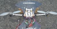
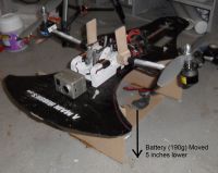
I crashed it after i "whiskey throttled" the collective. But im rebuilding now, fortunately tilt rotor with fixed pitch dont have all the expensive little parts that helis have.
Im hoping this among other sources will help me avoid saturation of the several integrals ill be maintaning...
Patrick, Sun Jul 01 2012, 06:01AM
AndrewM wrote ...
Video please? What was the final configuration?
yep let me post a pic for now, im trying to figure out how to use a GoPro ATM.Video please? What was the final configuration?


I crashed it after i "whiskey throttled" the collective. But im rebuilding now, fortunately tilt rotor with fixed pitch dont have all the expensive little parts that helis have.
Im hoping this among other sources will help me avoid saturation of the several integrals ill be maintaning...

Re: CSU Chico Tilt Rotor Flying Machine, (Airframe and Electronics, 2 of 3).
Steve Conner, Sun Jul 01 2012, 08:50AM
Good stuff! I see you're not using the wooden pole to damp oscillations any more. How did you get rid of that? From the pics it looks like you're dangling the battery pack underneath now.
Steve Conner, Sun Jul 01 2012, 08:50AM
Good stuff! I see you're not using the wooden pole to damp oscillations any more. How did you get rid of that? From the pics it looks like you're dangling the battery pack underneath now.
Re: CSU Chico Tilt Rotor Flying Machine, (Airframe and Electronics, 2 of 3).
Patrick, Sun Jul 01 2012, 11:40AM
second, hanging the battery was a huge help, and remember i said i was wondering if the CL should be well above the CG, well it pretty much has to be (a pendulum) or pitch changes are erratic or have no effect.
i like this more than my quad, as theres half the props, half the motors, and half the ESCs, so its cheap to fix. And a camera/sensors are easier to mount with better field of view than from a quad.
Patrick, Sun Jul 01 2012, 11:40AM
Steve Conner wrote ...
Good stuff! I see you're not using the wooden pole to damp oscillations any more. How did you get rid of that? From the pics it looks like you're dangling the battery pack underneath now.
First, as for the pole. Yes we've done away with it, now that ive pushed some mass out left and right, those rotational moments are slower and the gyro+math can keep up from the kk board.Good stuff! I see you're not using the wooden pole to damp oscillations any more. How did you get rid of that? From the pics it looks like you're dangling the battery pack underneath now.
second, hanging the battery was a huge help, and remember i said i was wondering if the CL should be well above the CG, well it pretty much has to be (a pendulum) or pitch changes are erratic or have no effect.
i like this more than my quad, as theres half the props, half the motors, and half the ESCs, so its cheap to fix. And a camera/sensors are easier to mount with better field of view than from a quad.
Re: CSU Chico Tilt Rotor Flying Machine, (Airframe and Electronics, 2 of 3).
AndrewM, Tue Jul 03 2012, 03:13PM
VIDEO!!!
You've just built a tiltrotor, you really expect me to believe you can't figure out how to upload some vids?
AndrewM, Tue Jul 03 2012, 03:13PM
VIDEO!!!
You've just built a tiltrotor, you really expect me to believe you can't figure out how to upload some vids?
Re: CSU Chico Tilt Rotor Flying Machine, (Airframe and Electronics, 2 of 3).
Patrick, Tue Jul 03 2012, 05:32PM
i can build UAVs, and plan to build spacecraft, but they still wont give me a degree in EE!
Patrick, Tue Jul 03 2012, 05:32PM
AndrewM wrote ...
VIDEO!!!
You've just built a tiltrotor, you really expect me to believe you can't figure out how to upload some vids?
VIDEO!!!
You've just built a tiltrotor, you really expect me to believe you can't figure out how to upload some vids?
i can build UAVs, and plan to build spacecraft, but they still wont give me a degree in EE!
Re: CSU Chico Tilt Rotor Flying Machine, (Airframe and Electronics, 2 of 3).
Steve Conner, Tue Jul 03 2012, 09:49PM
You don't need a degree in EE to operate a GoPro! Vids or it didn't happen
PS: You might need one before anyone will let you near a spacecraft.
Steve Conner, Tue Jul 03 2012, 09:49PM
You don't need a degree in EE to operate a GoPro! Vids or it didn't happen

PS: You might need one before anyone will let you near a spacecraft.
Re: CSU Chico Tilt Rotor Flying Machine, (Airframe and Electronics, 2 of 3).
AndrewM, Tue Jul 03 2012, 10:18PM
Ha, if that was the requirement nothing would ever get built around here! Based on the number of connector jackposts that get twisted off, inspection mirrors shorting out battery cells, and ESD bags left over TC&R antennas I'd wager a HS diploma isn't even a requirement...
I propose a boycott of all of Patrick's threads until he posts video.
AndrewM, Tue Jul 03 2012, 10:18PM
Steve Conner wrote ...
PS: You might need one before anyone will let you near a spacecraft.
PS: You might need one before anyone will let you near a spacecraft.
Ha, if that was the requirement nothing would ever get built around here! Based on the number of connector jackposts that get twisted off, inspection mirrors shorting out battery cells, and ESD bags left over TC&R antennas I'd wager a HS diploma isn't even a requirement...
I propose a boycott of all of Patrick's threads until he posts video.
Re: CSU Chico Tilt Rotor Flying Machine, (Airframe and Electronics, 2 of 3).
Patrick, Wed Jul 04 2012, 02:21AM
As for Steve Connor's point, highly educated idiots F things up all the time... those NASA idiots blew up 2 space shuttles killing 14 with nothing more than their own incompetence.
Id rather have competent people without degrees, than incompetent idoits with degrees. Especially if im the one sitting on 800 tons of ammonium perchlorate.
Patrick, Wed Jul 04 2012, 02:21AM
AndrewM wrote ...
I propose a boycott of all of Patrick's threads until he posts video.
ok ok ill post one tomorrow for sure, my fiberglass landing skid is a little weak at the moment though.I propose a boycott of all of Patrick's threads until he posts video.
As for Steve Connor's point, highly educated idiots F things up all the time... those NASA idiots blew up 2 space shuttles killing 14 with nothing more than their own incompetence.
Id rather have competent people without degrees, than incompetent idoits with degrees. Especially if im the one sitting on 800 tons of ammonium perchlorate.
Re: CSU Chico Tilt Rotor Flying Machine, (Airframe and Electronics, 2 of 3).
Patrick, Thu Jul 05 2012, 11:39PM
OK video on the way!!!
EDIT: im in the middle of a california forest and my cell-interent connection isnt worth a dam atm. sorry.
heres a more primative tilt rotor with 3 motors...
Patrick, Thu Jul 05 2012, 11:39PM
OK video on the way!!!
EDIT: im in the middle of a california forest and my cell-interent connection isnt worth a dam atm. sorry.
heres a more primative tilt rotor with 3 motors...

Re: CSU Chico Tilt Rotor Flying Machine, (Airframe and Electronics, 2 of 3).
AndrewM, Fri Jul 06 2012, 06:05AM
You disappoint me. :(
AndrewM, Fri Jul 06 2012, 06:05AM
You disappoint me. :(
Re: CSU Chico Tilt Rotor Flying Machine, (Airframe and Electronics, 2 of 3).
Steve Conner, Fri Jul 06 2012, 01:46PM
The Panther looks cool, however I'm disappointed that the rear rotor doesn't tilt backwards and act as a third propeller when transitioning to flight. :( Maybe they decided that it wasn't worth the extra complexity, but it would have looked neat.
Did I mention, we want video! >____>;
I also think it is a tad unfair that so-called grown-ups get to spend defence money on building RC planes and playing with them.
Re: CSU Chico Tilt Rotor Flying Machine, (Airframe and Electronics, 2 of 3).
Patrick, Fri Jul 06 2012, 11:06PM
it looks like they turn it off when they dont need it, thats why i said its more primative then mine or any true tilt rotor. they effectivley have a tri rotor some of the time, then dead wieght the rest of the time... every ounce of dead whiegt means an ounce of battery, fuel, bullets or High explosives not carried to the battlefield. cool idea but still primative.
Re: CSU Chico Tilt Rotor Flying Machine, (Airframe and Electronics, 2 of 3).
Patrick, Mon Jul 09 2012, 07:37PM
Video!
fast forward to 3:25 to see it really fly.
eventually i get it to fly, break a prop and most of the other good flying happens off camera. But this isthe best i have.
its too unstable with just 3 gyros, it really needs 3 accelerometers, even my ace test pilot Corey Kohler is pressed to the limit to keep it in a hover.
Re: CSU Chico Tilt Rotor Flying Machine, (Airframe and Electronics, 2 of 3).
AndrewM, Mon Jul 09 2012, 10:02PM
Yay video thanks!!
That rod is doing you zero good if its not fastened on tightly. Also from the looks of things you need a rod or something stabilizing the pitch direction too.
AndrewM, Mon Jul 09 2012, 10:02PM
Yay video thanks!!
That rod is doing you zero good if its not fastened on tightly. Also from the looks of things you need a rod or something stabilizing the pitch direction too.
Re: CSU Chico Tilt Rotor Flying Machine, (Airframe and Electronics, 2 of 3).
Patrick, Mon Jul 09 2012, 10:06PM
really, the sticks help stability, yet there best purpose is saving props.
EDIT 5:10pm : ive solved the roll oscillation again, by readjusting the roll pot with two better sticks attached. Then crashed it in real bad, striped the titanium gears again. dam it.
Patrick, Mon Jul 09 2012, 10:06PM
AndrewM wrote ...
Yay video thanks!!
That rod is doing you zero good if its not fastened on tightly. Also from the looks of things you need a rod or something stabilizing the pitch direction too.
yep before i had the GoPro cam, i did have two good sticks on there and the fastend better, it did make a differecne.Yay video thanks!!
That rod is doing you zero good if its not fastened on tightly. Also from the looks of things you need a rod or something stabilizing the pitch direction too.
really, the sticks help stability, yet there best purpose is saving props.
EDIT 5:10pm : ive solved the roll oscillation again, by readjusting the roll pot with two better sticks attached. Then crashed it in real bad, striped the titanium gears again. dam it.
Re: CSU Chico Tilt Rotor Flying Machine, (Airframe and Electronics, 2 of 3).
Patrick, Tue Jul 10 2012, 04:31PM
ok ive been folowing the explanations from these two sites:
 PID in C code for position.
 math and reasoning behind both velocity and position PIDs.
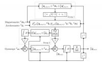
which parts in the below pic are the P the I and the D ?

im thinking the first part up to the + sign is the P, then the I and last the D, and is that "K sub 0" or "K sub i"?
Patrick, Tue Jul 10 2012, 04:31PM
ok ive been folowing the explanations from these two sites:
 PID in C code for position.
  math and reasoning behind both velocity and position PIDs.
which parts in the below pic are the P the I and the D ?
im thinking the first part up to the + sign is the P, then the I and last the D, and is that "K sub 0" or "K sub i"?
Re: CSU Chico Tilt Rotor Flying Machine, (Airframe and Electronics, 2 of 3).
Ken M., Tue Jul 10 2012, 04:51PM
ATM I can't find it but I know In a previous version of Aeroquad had the arduino code for a PID loop but heres a Link to the repository.
Ken M., Tue Jul 10 2012, 04:51PM
ATM I can't find it but I know In a previous version of Aeroquad had the arduino code for a PID loop but heres a Link to the repository.

Re: CSU Chico Tilt Rotor Flying Machine, (Airframe and Electronics, 2 of 3).
AndrewM, Tue Jul 10 2012, 05:44PM
That code appears to be differentiating position feedback to get velocity. You, on the other hand, have a gyro so you can get velocity data directly.
AndrewM, Tue Jul 10 2012, 05:44PM
That code appears to be differentiating position feedback to get velocity. You, on the other hand, have a gyro so you can get velocity data directly.
Re: CSU Chico Tilt Rotor Flying Machine, (Airframe and Electronics, 2 of 3).
Patrick, Thu Jul 12 2012, 02:34AM
IMPROVED!
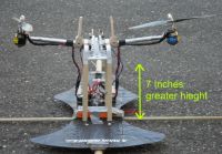
its now easy enough for any dope to fly.
Patrick, Thu Jul 12 2012, 02:34AM
IMPROVED!

its now easy enough for any dope to fly.
Re: CSU Chico Tilt Rotor Flying Machine, (Airframe and Electronics, 2 of 3).
AndrewM, Thu Jul 12 2012, 07:04AM
Wee, looking better.
Are you still limited to hops like that or have you achieved longer flights?
AndrewM, Thu Jul 12 2012, 07:04AM
Wee, looking better.
Are you still limited to hops like that or have you achieved longer flights?
Re: CSU Chico Tilt Rotor Flying Machine, (Airframe and Electronics, 2 of 3).
Patrick, Thu Jul 12 2012, 07:07AM
i can muddle along in 10-15 second sloppy hovers.
If i change my dual rates and exponential i think i can get it stable for minutes at a time. Ill do this first thing tomarrow.
Patrick, Thu Jul 12 2012, 07:07AM
i can muddle along in 10-15 second sloppy hovers.
If i change my dual rates and exponential i think i can get it stable for minutes at a time. Ill do this first thing tomarrow.
Re: CSU Chico Tilt Rotor Flying Machine, (Airframe and Electronics, 2 of 3).
Patrick, Sun Jul 15 2012, 02:58AM
ok Ive been doing some thinking...
i want to use a ramp, to initially change acceleration states, this will avoid wind-up errors in domain, while setting a maximum velocity allowable will avoid wind-up in range.
ive also been looking at tinkerforge:
Patrick, Sun Jul 15 2012, 02:58AM
ok Ive been doing some thinking...
i want to use a ramp, to initially change acceleration states, this will avoid wind-up errors in domain, while setting a maximum velocity allowable will avoid wind-up in range.
ive also been looking at tinkerforge:


Re: CSU Chico Tilt Rotor Flying Machine, (Airframe and Electronics, 2 of 3).
Patrick, Tue Jul 17 2012, 05:29AM
new vids

the first step, a PI loop.
SP = setpoint (input form pitch stick), m/s
PV = process variable (output for feedback), m/s
MV = Manipulated variable (control signal out), degrees of tilt.
so for this PI loop , i would assign meter per second values to pitch stick position (fore and aft speed) then use the accelerometer to judge the current velocity, and adjust as needed. Then repeat as funtion prototype calls for each axis.
but as for the ugly part, the gyros must be able to contribute too !? so how do i let the accelerometers have there say and then the gyros? Obviously, the accels are responsible for translation, the gyros for rotation.
is it possible that i have to run two PIDs in parallel one the the gyro's commanded tilt (position PID), the other for the accelerations needed duration, (the velocity PID?).?
EDIT: if the gyro PI tilts then degees/seconds are output, while the Accel PI keeps track of velcity/time. If that is the case then i think the two must be in series, not parallel as i wrongly stated above..
Patrick, Tue Jul 17 2012, 05:29AM
new vids

the first step, a PI loop.
SP = setpoint (input form pitch stick), m/s
PV = process variable (output for feedback), m/s
MV = Manipulated variable (control signal out), degrees of tilt.
so for this PI loop , i would assign meter per second values to pitch stick position (fore and aft speed) then use the accelerometer to judge the current velocity, and adjust as needed. Then repeat as funtion prototype calls for each axis.
but as for the ugly part, the gyros must be able to contribute too !? so how do i let the accelerometers have there say and then the gyros? Obviously, the accels are responsible for translation, the gyros for rotation.
is it possible that i have to run two PIDs in parallel one the the gyro's commanded tilt (position PID), the other for the accelerations needed duration, (the velocity PID?).?
EDIT: if the gyro PI tilts then degees/seconds are output, while the Accel PI keeps track of velcity/time. If that is the case then i think the two must be in series, not parallel as i wrongly stated above..
Re: CSU Chico Tilt Rotor Flying Machine, (Airframe and Electronics, 2 of 3).
WaveRider, Tue Jul 17 2012, 01:44PM
If you want full sensor fusion between accelerometers , gyros, even visual, GPS and user data, you can't beat the Kalman Filter approach. You are on the right track with the PID controllers. What is missing (as you discovered) is a way to put all the sensor data together. The Kalman filter's ability to handle vectorized data is very convenient..but can get cumbersome particularly if non-linear physical models are used.


Re: CSU Chico Tilt Rotor Flying Machine, (Airframe and Electronics, 2 of 3).
Patrick, Tue Jul 17 2012, 08:24PM
OK, if started a post with DIY Drones, under the screen name "Test Pilot Mafia" unfortunately my post is going unseen, this has happened before in other places too.
Me ->
edit: pendulum-cart model :
bicopter:
Quote: "The SCORPID-500 is now fully stabilised and controlled by a 9 DOF IMU (ArduIMU+ v2, HMC5843, GPS with firmware TriStab v3.3 JLN). The SCORPID-500 VTOL UAV uses an innovative design based on Gary Gress concept from Gress Aero. The Oblique Active Tilting (OAT) at 45° of the twin engines allows a full pitch control by using the induced gyroscopic moment."
OAT = oblique active tilting,
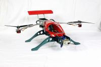
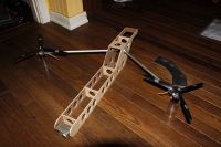
note the angle allows a single tilt axis to cross both the roll and pitch planes!
Patrick, Tue Jul 17 2012, 08:24PM
OK, if started a post with DIY Drones, under the screen name "Test Pilot Mafia" unfortunately my post is going unseen, this has happened before in other places too.
Me ->

edit: pendulum-cart model :

bicopter:

Quote: "The SCORPID-500 is now fully stabilised and controlled by a 9 DOF IMU (ArduIMU+ v2, HMC5843, GPS with firmware TriStab v3.3 JLN). The SCORPID-500 VTOL UAV uses an innovative design based on Gary Gress concept from Gress Aero. The Oblique Active Tilting (OAT) at 45° of the twin engines allows a full pitch control by using the induced gyroscopic moment."
OAT = oblique active tilting,


note the angle allows a single tilt axis to cross both the roll and pitch planes!
Re: CSU Chico Tilt Rotor Flying Machine, (Airframe and Electronics, 2 of 3).
Patrick, Wed Jul 18 2012, 09:33PM
OAT = Oblique Active Tiliting, singular or dual.
the OAT allows landing on tilted surfaces, which quads and tri's cant do.
PDF:
]oat.pdf[/file]
Ive been told/fear that possibly my current design wont work. supposedly (and theres no documentation from kkmulticopter) you would need a low (long vertical destance) CG and a very low inertia prop/motor combo. or the system has no hope of becoming stable.
My design was the typical FAAT type tilt rotor, but the OAT may be far better, especially for smal compact UAVs.
Re: CSU Chico Tilt Rotor Flying Machine, (Airframe and Electronics, 2 of 3).
Patrick, Tue Jul 24 2012, 02:32AM
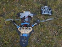
Its still wont hold a hover but at least i can show definate pitch control.
OK, with the above ive just demonstrated that :
1) yaw works as predicted.
2) using gyro scopic forces does indeed effectively control pitch.
3) the gyro prop idea (Greg Gress) seems to still work with the KKmulticopter/flycam/twin copter board.
So, OAT is defineatly superior to FAAT (fore aft active tilting)...
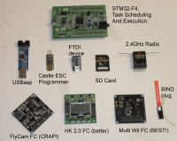
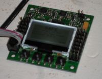
I plan to switch from the primative KK/flycam baord to the HK 2.0 board seen here.
the problem with the flycam boards is that they seem primative, with no advice or specs given to build the airframe, for 140$ you get the board and some simple instructions and settings, but nothing more. And ive been told that the KK boards dont have PIDs, Kalman filters or any of the usuall stability strategies, if true i dont know how it works, just those three magic potentiometers. it has only gyros.
the HK 2.0 board has an LCd screen, buttons, and an editor to change PI, PD, PID type settings, for each axis for upto eight motors, it has both accelerometers and gyros. All for just $34.
Patrick, Tue Jul 24 2012, 02:32AM

Its still wont hold a hover but at least i can show definate pitch control.
OK, with the above ive just demonstrated that :
1) yaw works as predicted.
2) using gyro scopic forces does indeed effectively control pitch.
3) the gyro prop idea (Greg Gress) seems to still work with the KKmulticopter/flycam/twin copter board.
So, OAT is defineatly superior to FAAT (fore aft active tilting)...
I plan to switch from the primative KK/flycam baord to the HK 2.0 board seen here.

the problem with the flycam boards is that they seem primative, with no advice or specs given to build the airframe, for 140$ you get the board and some simple instructions and settings, but nothing more. And ive been told that the KK boards dont have PIDs, Kalman filters or any of the usuall stability strategies, if true i dont know how it works, just those three magic potentiometers. it has only gyros.
the HK 2.0 board has an LCd screen, buttons, and an editor to change PI, PD, PID type settings, for each axis for upto eight motors, it has both accelerometers and gyros. All for just $34.
Re: CSU Chico Tilt Rotor Flying Machine, (Airframe and Electronics, 2 of 3).
Patrick, Wed Jul 25 2012, 03:50AM
Servos !!!
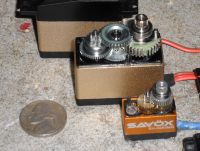
Tiny, Tiny, Tiny... Beefy, Beefy, Beefy
So far we have:
two Castle ESCs 50 amp upto 34 volts. (w 5 amp BEC)
two e-flite power 10 motors.
10 x 3.8 props ccw and cw. (APC props)
one Flycam Blackboard. (Twin Copter Flash)
two savox micro servos. (SH-263-MG)
two MKS digital, metal gear servos, standard size 140oz torque, (DS1009)
8 plastic servos analog.
one lipo 14.8 4 cell, 2200mah
one lipo 11.1 3 cell, 2200mah
one HiTec X4 charger

Patrick, Wed Jul 25 2012, 03:50AM
Servos !!!

Tiny, Tiny, Tiny... Beefy, Beefy, Beefy
So far we have:
two Castle ESCs 50 amp upto 34 volts. (w 5 amp BEC)
two e-flite power 10 motors.
10 x 3.8 props ccw and cw. (APC props)
one Flycam Blackboard. (Twin Copter Flash)
two savox micro servos. (SH-263-MG)
two MKS digital, metal gear servos, standard size 140oz torque, (DS1009)
8 plastic servos analog.
one lipo 14.8 4 cell, 2200mah
one lipo 11.1 3 cell, 2200mah
one HiTec X4 charger

Re: CSU Chico Tilt Rotor Flying Machine, (Airframe and Electronics, 2 of 3).
Patrick, Thu Jul 26 2012, 10:31PM
Changes have been made to the wing torque tubes:

Left and right torque tube couplers. as planned to be made.
MWC, se type controller:
] newbies_guide_to_setting_up_crius_multiwii_se_boar d_v4-22-12.pdf[/file]
OK ive made the decision to buy the HK 2.0 controller:

Graphics for configs and prop direction.

real-time IMU checking.

Menus

PID and such settings, no laptop or Basp needed.
Patrick, Thu Jul 26 2012, 10:31PM
Changes have been made to the wing torque tubes:
Left and right torque tube couplers. as planned to be made.
MWC, se type controller:
] newbies_guide_to_setting_up_crius_multiwii_se_boar d_v4-22-12.pdf[/file]
OK ive made the decision to buy the HK 2.0 controller:

Graphics for configs and prop direction.

real-time IMU checking.

Menus

PID and such settings, no laptop or Basp needed.
Re: CSU Chico Tilt Rotor Flying Machine, (Airframe and Electronics, 2 of 3).
Steve Conner, Fri Jul 27 2012, 10:15AM
Nice, how does it compare to the OpenPilot system?
Steve Conner, Fri Jul 27 2012, 10:15AM
Nice, how does it compare to the OpenPilot system?
Re: CSU Chico Tilt Rotor Flying Machine, (Airframe and Electronics, 2 of 3).
Patrick, Fri Jul 27 2012, 07:01PM
i think i stick with what other bicopter piltos are using, just so i have people to help me when stuff stops working right.
Patrick, Fri Jul 27 2012, 07:01PM
Steve Conner wrote ...
Nice, how does it compare to the OpenPilot system?
well the HK and Crius MWC controllers support bicopter mode, but open pilot seems not to.Nice, how does it compare to the OpenPilot system?
i think i stick with what other bicopter piltos are using, just so i have people to help me when stuff stops working right.
Re: CSU Chico Tilt Rotor Flying Machine, (Airframe and Electronics, 2 of 3).
Patrick, Fri Sept 28 2012, 06:27AM
New big devlopements are on the way... Multi wii (Crius AIO type) with variable PIDs on each axis has been assembled, testing to come this weekend... its been awhile since ive posted here, but ive been continuously working on it...
Patrick, Fri Sept 28 2012, 06:27AM
New big devlopements are on the way... Multi wii (Crius AIO type) with variable PIDs on each axis has been assembled, testing to come this weekend... its been awhile since ive posted here, but ive been continuously working on it...
Print this page
