If you need assistance, please send an email to forum at 4hv dot org. To ensure your email is not marked as spam, please include the phrase "4hv help" in the subject line. You can also find assistance via IRC, at irc.shadowworld.net, room #hvcomm.
Support 4hv.org!
Donate:
4hv.org is hosted on a dedicated server. Unfortunately, this server costs and we rely on the help of site members to keep 4hv.org running. Please consider donating. We will place your name on the thanks list and you'll be helping to keep 4hv.org alive and free for everyone. Members whose names appear in red bold have donated recently. Green bold denotes those who have recently donated to keep the server carbon neutral.
Special Thanks To:
Aaron Holmes
Aaron Wheeler
Adam Horden
Alan Scrimgeour
Andre
Andrew Haynes
Anonymous000
asabase
Austin Weil
barney
Barry
Bert Hickman
Bill Kukowski
Blitzorn
Brandon Paradelas
Bruce Bowling
BubeeMike
Byong Park
Cesiumsponge
Chris F.
Chris Hooper
Corey Worthington
Derek Woodroffe
Dalus
Dan Strother
Daniel Davis
Daniel Uhrenholt
datasheetarchive
Dave Billington
Dave Marshall
David F.
Dennis Rogers
drelectrix
Dr. John Gudenas
Dr. Spark
E.TexasTesla
eastvoltresearch
Eirik Taylor
Erik Dyakov
Erlend^SE
Finn Hammer
Firebug24k
GalliumMan
Gary Peterson
George Slade
GhostNull
Gordon Mcknight
Graham Armitage
Grant
GreySoul
Henry H
IamSmooth
In memory of Leo Powning
Jacob Cash
James Howells
James Pawson
Jeff Greenfield
Jeff Thomas
Jesse Frost
Jim Mitchell
jlr134
Joe Mastroianni
John Forcina
John Oberg
John Willcutt
Jon Newcomb
klugesmith
Leslie Wright
Lutz Hoffman
Mads Barnkob
Martin King
Mats Karlsson
Matt Gibson
Matthew Guidry
mbd
Michael D'Angelo
Mikkel
mileswaldron
mister_rf
Neil Foster
Nick de Smith
Nick Soroka
nicklenorp
Nik
Norman Stanley
Patrick Coleman
Paul Brodie
Paul Jordan
Paul Montgomery
Ped
Peter Krogen
Peter Terren
PhilGood
Richard Feldman
Robert Bush
Royce Bailey
Scott Fusare
Scott Newman
smiffy
Stella
Steven Busic
Steve Conner
Steve Jones
Steve Ward
Sulaiman
Thomas Coyle
Thomas A. Wallace
Thomas W
Timo
Torch
Ulf Jonsson
vasil
Vaxian
vladi mazzilli
wastehl
Weston
William Kim
William N.
William Stehl
Wesley Venis
The aforementioned have contributed financially to the continuing triumph of 4hv.org. They are deserving of my most heartfelt thanks.
Registered Member #2018
Joined: Tue Mar 10 2009, 09:56AM
Location: Switzerland
Posts: 74
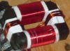
Dear hv-freaks out there
I recently got a nice (big) 4kVA resin potted HV-Transformer, it does 15kV/266mA from 400V/10A main input. What do you think would be the best current limiting device for this to achieve 10A at 400V when drawing arcs? An inductance of about 130mH would do (if I'm right), but I don't know how to achieve this. Unfortunately I have no variac for 400V yet, maybe I try with my 0...260V variac at first. At 230V the transformer should put out about 8.6kV.
Registered Member #882
Joined: Sat Jul 07 2007, 04:32AM
Location:
Posts: 103
An inductance of about 130mH would do (if I'm right), but I don't know how to achieve this.
Something like this. Inductive ballast for that power level means lots of copper and lots of core. That's one attractive transformer though, good luck on lighting it up
Registered Member #2463
Joined: Wed Nov 11 2009, 03:49AM
Location:
Posts: 1546
Trying to balast it with a series inductance may lead to saturation in the external coil which would cause steep risetimes and modes of action in the secondary you dont want (like flashovers intra-winding due to resonances.) Of couse arcing the seconday will too,
A cheap way would be a nice bank of 100 watt incandescant lamps.
I would meause the DC resistance of the pri and sec to the highest accuracy you can, at a stable storage temperature as well as the unloaded voltamps. Then you could tell if something happened to it later on. Make sure your ohmeter isn't an auto ranging type. You may have to wait a few seconds for a reading on the secondary too.
The way to take DC measurements on high voltage big iron is to short the winding, connect the meter, unshort it ,take the reading, short it again, take the meter away.
Teaching the apprentice about CEMF by having him hold the probes sans shorting switch is optional.
Registered Member #1232
Joined: Wed Jan 16 2008, 10:53PM
Location: Doon tha Toon!
Posts: 881
A ballast consisting of a laminated E-I core set with adjustable gap in the magnetic path is very efficient and flexible if done properly.
I got the ones on my website made by a local transformer manufacturer because I was very busy at the time, but they are very easy to make yourself. All you need is a suitable core set, a reel of wire, a variac, AC volt meter and AC ammeter.
If you select the right core CSA and number of turns the core won't saturate with the gap closed, and increasing the gap will take the core further away from saturation so you have no worries there.
As for the resonance, that is usually what you want the ballast for:- To implement AC resonant charging. If you use resistive charging the PSU will never be more than 50% efficient because as much energy will be dissipated in the ballast as gets stored in the capacitor.
Registered Member #2463
Joined: Wed Nov 11 2009, 03:49AM
Location:
Posts: 1546
With your variac and an ammeter find out how many volts are across the primary, with the secondary shorted, when the 10 amps are flowing. That is the impedance voltage of the unit. Your balast will have to cause that same voltage to drop across the primary with the secondary shorted.
If you uses a series (net)capacitive balast you need to know if any load on the secondary except a short circuit can cause the primary voltage to rise above 400 volts.
Do you know what that transformer was designed to do ?
Registered Member #2018
Joined: Tue Mar 10 2009, 09:56AM
Location: Switzerland
Posts: 74
Many thanks for all the advice.
@radiotech:
Do you know what that transformer was designed to do ?
Thank you for all your information on this. The previous owner commissioned this transformer at a transformer manufacturer just for building a tesla coil But this standard design of transformers seem to be built for stepping up and steppping down the voltage in little isolated energy distribution networks. There are higher power levels available as well, but for my high voltage experiments the transformer has a good size. Bigger is not always better Besides that I didn't want to have an oil filled unit.
@GeordieBoy:
A ballast consisting of a laminated E-I core set with adjustable gap in the magnetic path is very efficient and flexible if done properly.
At first - very cool webpage you've got! Many tips and hints, I really like it and I was several times there for trying to learn some theory behind the things. Thank you for your great documentation!
Did you measure the inductance of your ballast after you designed it? If yes, did you use a normal LCR bridge for that? Because I heard of the problem, that the little current of an LCR bridge is not enough for magnetizing the core of the inductor and that this would lead to a wrong test-result?
Registered Member #1232
Joined: Wed Jan 16 2008, 10:53PM
Location: Doon tha Toon!
Posts: 881
An LCR bridge or cheap DVM is unlikely to provide enough power to magnetise a large iron core.
The best way to check the inductance of a power reactor is to connect it across a known AC voltage source and measure the current. A mains driven variac with an AC volt-meter can act as the variable AC voltage source and you can measure the current with an AC clamp meter (or an in-line ammeter.)
Usually it is the current draw you are interested in more than the actual inductance, so if you test it across a variac you can often leave out the calculation of the inductance from v, f and i anyway.
It also worth mentioning that when you are testing an inductive ballast for long-term heating you can reduce the line-current draw by connecting PFC capacitors across the ballast during the test. This reduces the load current seen by the variac and all of the wiring leading up to it! With the right amount of PFC capacitance connected during the test, you can have 50A or more circulating in the ballast inductor, but the only current drawn from the wall will be an amp or so to offset the heating in the core and windings! It's a very useful technique to employ if you want to test a 50A or 100A reactor in your home where you only have a 13A socket available!
Registered Member #2463
Joined: Wed Nov 11 2009, 03:49AM
Location:
Posts: 1546
The transformer looks like a "potential transformer" at first glance.
A potential transformer is used in power instrumentation to drop the high voltage bus down the the level the metering and relaying uses. That 2 % on the label may be the % impedance, that is the percentage of voltage on one winding causing rated current to flow with the other one shorted.
A precise translation to English of the label would be nice.
Kurzschlussspannung seems to be the translation of impedance voltage.
Good instrumation transformers are hard to get cheaply.
Registered Member #2018
Joined: Tue Mar 10 2009, 09:56AM
Location: Switzerland
Posts: 74
@radiotech: Thanks for your input. It's definitely not a potential transformer. I've got three potential transformers, but this one is much bigger, much heavier and can be loaded with 4kVA all the time. Even with a very big potential transformer this is not possible (at least I don't know of any PT with such a power rating, maybe at most for a very short time). And here in Europe every potential transformer has a "secondary" of 100V for measuring use. 400V would be very uncommon for an instrument transformer.
I don't know, were you saw the word "Kurzschlussspannung". Kurzschlussspannung means "short-circuit-voltage" when translated directly, I think it's the primary voltage, which is present when the transformer is completely shorted on its secondary and the rated current of 10.3A flows (not sure).
"Trenntrafo" means an earth-isolated transformer with two HV-bushings, "ED" means Einschalt-Dauer" or "on-time" in English. "ta40" means the ambient temperature can be up to 40°C for the given power rating. P means power rating (4kVA), PRI means primary voltage and current, SEC is secondary voltage and current, 12A FST means the transformer should be fused with 12A on the primary side, ISO 40kVeff means the secondary is isolated for voltage levels / transients of max. 40kV.
By the way, these are my three potential transformers:
@GeordieBoy: Thanks again for your helpful hints. I will try to construct an inductive ballast like yours, maybe there's also a way to abuse some low-voltage transformers as a ballast.
This site is powered by e107, which is released under the GNU GPL License. All work on this site, except where otherwise noted, is licensed under a Creative Commons Attribution-ShareAlike 2.5 License. By submitting any information to this site, you agree that anything submitted will be so licensed. Please read our Disclaimer and Policies page for information on your rights and responsibilities regarding this site.


 Ballast for a HV-Transformer