If you need assistance, please send an email to forum at 4hv dot org. To ensure your email is not marked as spam, please include the phrase "4hv help" in the subject line. You can also find assistance via IRC, at irc.shadowworld.net, room #hvcomm.
Support 4hv.org!
Donate:
4hv.org is hosted on a dedicated server. Unfortunately, this server costs and we rely on the help of site members to keep 4hv.org running. Please consider donating. We will place your name on the thanks list and you'll be helping to keep 4hv.org alive and free for everyone. Members whose names appear in red bold have donated recently. Green bold denotes those who have recently donated to keep the server carbon neutral.
Special Thanks To:
Aaron Holmes
Aaron Wheeler
Adam Horden
Alan Scrimgeour
Andre
Andrew Haynes
Anonymous000
asabase
Austin Weil
barney
Barry
Bert Hickman
Bill Kukowski
Blitzorn
Brandon Paradelas
Bruce Bowling
BubeeMike
Byong Park
Cesiumsponge
Chris F.
Chris Hooper
Corey Worthington
Derek Woodroffe
Dalus
Dan Strother
Daniel Davis
Daniel Uhrenholt
datasheetarchive
Dave Billington
Dave Marshall
David F.
Dennis Rogers
drelectrix
Dr. John Gudenas
Dr. Spark
E.TexasTesla
eastvoltresearch
Eirik Taylor
Erik Dyakov
Erlend^SE
Finn Hammer
Firebug24k
GalliumMan
Gary Peterson
George Slade
GhostNull
Gordon Mcknight
Graham Armitage
Grant
GreySoul
Henry H
IamSmooth
In memory of Leo Powning
Jacob Cash
James Howells
James Pawson
Jeff Greenfield
Jeff Thomas
Jesse Frost
Jim Mitchell
jlr134
Joe Mastroianni
John Forcina
John Oberg
John Willcutt
Jon Newcomb
klugesmith
Leslie Wright
Lutz Hoffman
Mads Barnkob
Martin King
Mats Karlsson
Matt Gibson
Matthew Guidry
mbd
Michael D'Angelo
Mikkel
mileswaldron
mister_rf
Neil Foster
Nick de Smith
Nick Soroka
nicklenorp
Nik
Norman Stanley
Patrick Coleman
Paul Brodie
Paul Jordan
Paul Montgomery
Ped
Peter Krogen
Peter Terren
PhilGood
Richard Feldman
Robert Bush
Royce Bailey
Scott Fusare
Scott Newman
smiffy
Stella
Steven Busic
Steve Conner
Steve Jones
Steve Ward
Sulaiman
Thomas Coyle
Thomas A. Wallace
Thomas W
Timo
Torch
Ulf Jonsson
vasil
Vaxian
vladi mazzilli
wastehl
Weston
William Kim
William N.
William Stehl
Wesley Venis
The aforementioned have contributed financially to the continuing triumph of 4hv.org. They are deserving of my most heartfelt thanks.
Registered Member #2779
Joined: Sat Apr 03 2010, 10:51AM
Location:
Posts: 7
Hi all ive been watching this site for ages and have finaly joined up! but anyways ill go straight to the point. when i make my capacitor bank can i put the capacitors on a prototype board or is there any downside to that? if you know an better altenitive to this please share im open to ideas. thanks in advance. btw im using at least 10 photoflash capacitors also would using 12 add alot of diffrence rather than 10?
Registered Member #2046
Joined: Sun Mar 22 2009, 01:12PM
Location: Stockholm, Sweden
Posts: 23
Most photoflash caps I've looked at are around 330V 80µF. So that'd make a difference of around 160µF.
800µF/960µF. I doubt it'll make a huge difference but it depends on projectile weight and the coil.
For such a lower power bank I personally don't think a prototype board will reduce the efficiency very much but you could just aswell solder them all to a thicker wire.
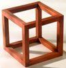
Like this: But obviously photocaps are smaller and you wouldn't need as thick wire. Sidenote: Caps in photo are 4x2(parallelxseries), you probably want your entire capbank in parallel.
Registered Member #90
Joined: Thu Feb 09 2006, 02:44PM
Location: Seattle, Washington
Posts: 301
I'm doubtful that a prototype board has sufficient contact area for good low-resistance connections. They are not designed for high-current applications; there is a high probability you'll fry the proto board itself.
Note that coilgun performance is sensitive to total loop resistance in the discharge path. You want resistance to be as low as possible. Even a few milliohms will reduce the peak current. This means using short wires and soldering all connections if possible. Even screw-on connections absolutely must be very tight with lots of contact area and clean wire.
Good luck, Barry "The majority of quotes in emails are misattributed to famous people." ~ Abraham Lincoln
Registered Member #162
Joined: Mon Feb 13 2006, 10:25AM
Location: United Kingdom
Posts: 3141
I used plain matrix board for my cap bank, 12 rows of 8 photoflash capacitors. The wiring side shows the tinned copper wire interconnects.
I used two 160V zeners in series per row to limit/balance the charge per capacitor and connected to diagonally opposite ends of the bank to equalise stress over all the capacitors during discharge. I've had this bank for many years with no problems (other than exploding a cheap dmm)
Registered Member #2779
Joined: Sat Apr 03 2010, 10:51AM
Location:
Posts: 7
ok so ive thought instead of puting all th capacitors in parrallel i would put it in in 4 rows of 3 capacitors in series to get more joules is esr a big factor in this set up? they are standard photoflash capacitors.
Registered Member #1525
Joined: Mon Jun 09 2008, 12:16AM
Location: America
Posts: 294
You won't get more energy by putting capacitors in series. When you series caps, you get a higher maximum voltage and less capacitance, which balances out and leaves the energy the same.
ESR does make a difference- that's why it's a good idea to avoid putting electrolytic capacitors in series if possible. However, since photoflash caps will be limited to low-to-medium amounts of energy, it might not make a noticeable difference in your case.
Registered Member #540
Joined: Mon Feb 19 2007, 07:49PM
Location: MIT
Posts: 969
You do get a higher energy when putting capacitors in series. The energy stored is (c*v^2)/2 so there is the same energy stored in the caps when you put them in series or in parallel. .5*(.5F)*(2V)^2=.5*(2F)*(1V). In series, the cap's ESR add and when they are in parallel, they just looks like resistors in series with the cap (no simplification if I am correct). I think it's fine to put electrolytic caps in series but you need to also put balancing resistors so that they charge evenly. Some people have used series electrolytic caps for filtering high voltages and they haven't had any problems. Like Barry said, the resistance is important but with the increased voltage from caps in series, you can get a higher peak current. As an example: 100V, 50mOhms, 1mF, 500uH results in a 134A peak decreasing to 0A in 2.22mS(not critically damped) and 200V, 100mOhms, 500uF, 500uH results in a 185A peak decreasing to 0A in 1.56mS (not critically damped).
Registered Member #2099
Joined: Wed Apr 29 2009, 12:22AM
Location: Los Altos, California
Posts: 1716
In other words, series gives you the same energy as parallel, for the same number of caps.
Banks of 12 caps in parallel, or 12 in series, or 3S4P combination, will each store 12 times the energy of a single cap. The resulting discharge dynamics will be very different if the load is unchanged, a qualification often omitted in threads on this topic. By using coils wound in the same volume with different wire gauges, you can get the same peak ampere-turns, same timing, and same damping from all 3 capacitor topologies. Then all 3 topologies will have the same current waveform and same ESR losses in each individual capacitor. (And same coilgun performance.)
Myke wrote ... ... Like Barry said, the resistance is important but with the increased voltage from caps in series, you can get a higher peak current. As an example: 100V, 50mOhms, 1mF, 500uH results in a 134A peak decreasing to 0A in 2.22mS(not critically damped) and 200V, 100mOhms, 500uF, 500uH results in a 185A peak decreasing to 0A in 1.56mS (not critically damped).
Myke's simulation examples are 1 cap and 2 caps in series. If we put the same 2 caps in parallel: 100 V, 25 mOhms, 2 mF, 500 uH, then Barry's awesome simulator gives 192 A and first half-cycle ending at 3.12 ms. So in this underdamped case (resistance << sqrt(L/C)) , the parallel and series banks yield essentially the same peak current and magnetic field (storing about 90% of the joules that were originally in the capacitors).
The pulse lasts twice as long in the 2P case, which is not necessarily good in a coilgun. With 2 caps in parallel and a coil with half the turns count: 100 V, 25 mOhms, 2 mF, 125 uH, the simulator gives 370 A and 1.56 ms. Exactly the same ampere-turns and timing as the 2S configuration with original coil.
Note that except for the last example, we have been changing the circuit R value as if it were entirely due to ESR of the capacitors, with no contribution from the coil.
This site is powered by e107, which is released under the GNU GPL License. All work on this site, except where otherwise noted, is licensed under a Creative Commons Attribution-ShareAlike 2.5 License. By submitting any information to this site, you agree that anything submitted will be so licensed. Please read our Disclaimer and Policies page for information on your rights and responsibilities regarding this site.


 Capacitor bank help


