 Induction heater inverter tracing Induction heater inverter tracing
|
|
|
IamSmooth
|
|
Sat Oct 10 2009, 09:09PM
|

|
|
 Registered Member #190
Joined: Fri Feb 17 2006, 12:00AM
Location:
Posts: 1567
|
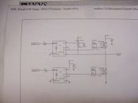
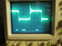
I have the inverter wired on a breadboard, so I know there is a lot of stray capacitance. I am using the FOD3180 gate drive chips off of the E1 and E2 outputs of the TL494. My test board has the chips running from 15v and the mosfet source is connected to 40-60v. The output from the half-bridge is going through a 200 non-inductive resistor to the mid-point of a capacitive divider: two 1uf/600v snubber caps connected in series from the high voltage to ground.
The tracing shown is from the resistor going to the divider.
I would like to know if the tracing is reasonable before I move foward. I see ringing on the low-to-high transition. I don't know if this is normal and just simply from the RC effect of the resistor/capacitive divider, or if I have to tweek something.
induction heater inverter
tracing


|
|
Back to top
|
|
Moderator(s): Chris Russell, Noelle, Alex, Tesladownunder, Dave Marshall, Dave Billington, Bjørn, Steve Conner, Wolfram, Kizmo, Mads Barnkob
|
|
Powered by e107 Forum System
|

