If you need assistance, please send an email to forum at 4hv dot org. To ensure your email is not marked as spam, please include the phrase "4hv help" in the subject line. You can also find assistance via IRC, at irc.shadowworld.net, room #hvcomm.
Support 4hv.org!
Donate:
4hv.org is hosted on a dedicated server. Unfortunately, this server costs and we rely on the help of site members to keep 4hv.org running. Please consider donating. We will place your name on the thanks list and you'll be helping to keep 4hv.org alive and free for everyone. Members whose names appear in red bold have donated recently. Green bold denotes those who have recently donated to keep the server carbon neutral.
Special Thanks To:
Aaron Holmes
Aaron Wheeler
Adam Horden
Alan Scrimgeour
Andre
Andrew Haynes
Anonymous000
asabase
Austin Weil
barney
Barry
Bert Hickman
Bill Kukowski
Blitzorn
Brandon Paradelas
Bruce Bowling
BubeeMike
Byong Park
Cesiumsponge
Chris F.
Chris Hooper
Corey Worthington
Derek Woodroffe
Dalus
Dan Strother
Daniel Davis
Daniel Uhrenholt
datasheetarchive
Dave Billington
Dave Marshall
David F.
Dennis Rogers
drelectrix
Dr. John Gudenas
Dr. Spark
E.TexasTesla
eastvoltresearch
Eirik Taylor
Erik Dyakov
Erlend^SE
Finn Hammer
Firebug24k
GalliumMan
Gary Peterson
George Slade
GhostNull
Gordon Mcknight
Graham Armitage
Grant
GreySoul
Henry H
IamSmooth
In memory of Leo Powning
Jacob Cash
James Howells
James Pawson
Jeff Greenfield
Jeff Thomas
Jesse Frost
Jim Mitchell
jlr134
Joe Mastroianni
John Forcina
John Oberg
John Willcutt
Jon Newcomb
klugesmith
Leslie Wright
Lutz Hoffman
Mads Barnkob
Martin King
Mats Karlsson
Matt Gibson
Matthew Guidry
mbd
Michael D'Angelo
Mikkel
mileswaldron
mister_rf
Neil Foster
Nick de Smith
Nick Soroka
nicklenorp
Nik
Norman Stanley
Patrick Coleman
Paul Brodie
Paul Jordan
Paul Montgomery
Ped
Peter Krogen
Peter Terren
PhilGood
Richard Feldman
Robert Bush
Royce Bailey
Scott Fusare
Scott Newman
smiffy
Stella
Steven Busic
Steve Conner
Steve Jones
Steve Ward
Sulaiman
Thomas Coyle
Thomas A. Wallace
Thomas W
Timo
Torch
Ulf Jonsson
vasil
Vaxian
vladi mazzilli
wastehl
Weston
William Kim
William N.
William Stehl
Wesley Venis
The aforementioned have contributed financially to the continuing triumph of 4hv.org. They are deserving of my most heartfelt thanks.
Registered Member #1451
Joined: Wed Apr 23 2008, 03:48AM
Location: Boulder, Co
Posts: 661
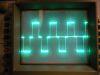
I need a way to eliminate interference on my scope trace. I have a signal from a piezo electric force sensor being fed via coax to my DSO about two feet away. There is a high voltage arc close to the sensor and the proximity can't be avoided. I get a good amount of interference from the high voltage and i'm wondering if there is a better way that i can shield the sensor feed. Also, the signal from the sensor is on the range of .14mV to about 50 mV. Since the high voltage is a fixed frequency, can i build a notch filter? Would it be easier to shield better? Do you think that the interference is traveling along the coax or is it penetrating the scope, in which case i could build a faraday cage? Sorry for all the questions. Any help is very appreciated!!!
Registered Member #30
Joined: Fri Feb 03 2006, 10:52AM
Location: Glasgow, Scotland
Posts: 6706
You should use both shielding and filtering. A Faraday cage around everything, wrap the wire from the sensor through a ferrite ring, isolate the sensor in its cage from the test rig to stop ground loops, etc.
You could add a notch filter (would be called a "trap" in this case) but I expect the presence of an arc will generate a lot of broadband noise besides the original HV power frequency.
Registered Member #1451
Joined: Wed Apr 23 2008, 03:48AM
Location: Boulder, Co
Posts: 661
So the sensor ground should be isolated from the rest of the circuitry? Here's another twist that could complicate filtering, the sensor outputs a very short pulse, around 1 ms that has to be differentiated from the noise of the high voltage. An idea i had: sync a transistor to the 555 oscillator for the high voltage transformer (flyback) so that it grounds the sensor output at the time that the high voltage pulses occur. Then i would just have to hope that sensor pulse occurs between the times when the output is grounded.
I'm not sure what the ferrite ring would do, but i bet it would smooth out pulses... am i right? would this damage the sensor output?
All i need is for my scope to be able to pick up the sensor pulse that is usually drowned out by the interference.
Registered Member #1232
Joined: Wed Jan 16 2008, 10:53PM
Location: Doon tha Toon!
Posts: 881
This sounds like a very difficult problem to solve.
The first thing I would suggest would be some amplification to the signal from the transducer, right at the transducer itself, or as close as you can get to it. Then send the amplified, and stiffened (low impedance output) down your coax cable to the scope or data aquisition card etc.
The ferrite core that Mr Conner mentioned is a very good idea. It acts as a common mode choke and prevents those currents running down the screen of the coax that you hinted at. Since the entire coaxial cable is wound around the ferrite core it does not alter the wanted signal in any way, but it is a well-established and effective way of preventing common-mode noise being conducted from the noisey end of a cable to the other end that you want to keep free of interference.
As for differentiating the small sensor output pulse from the spark gap hash, I think you might have problems. Do you need to process the results immediately in realtime? or can you run the experiment, gather the data and then analyse it later in something like Excel or Matlab?
If you can analyse the data later then you may be able to use digital filtering to remove the unwanted signal and/or boost the wanted signal to make it easier to see. Also if the wanted signal from the piezo has a particular known signiature shape, you can use things like correlation to pick it out from the forrest of noise. Likewise if it has a known frequency content then the FFT might prove a useful tool.
But, first stiffen up the signal, and shield and screen everything, pay attention to ground returns, and fit common mode chokes. Use the fancy data analysis stuff as a last resort if you've tried everything else and you're still stuck.
Registered Member #1451
Joined: Wed Apr 23 2008, 03:48AM
Location: Boulder, Co
Posts: 661
I had already thought of the amplifier, but discarded it for reasons that don't come back to me. Would a simple high bandwidth op amp be good enough to boost the the signal and stiffen the output?
Also, the whole setup with the sensor and arc is inside of an old and modified propane tank. The tank isn't used as anything dangerous, just a containment vessel. It is grounded, and i'm wandering if this would act like a faraday cage.
Would I put the chokes at the scope end and the sensor end of the coax? Does it matter what kind of ferrite I use? I have a bunch of toroids that I got off of the flybacks in computer monitors, a couple used as chokes, and a couple from the output side of ATX PSUs (the ones used for SSTCs).
I don't need to see the data right away, but my scope is an old crt style one so how would I output the data to my computer? The pulse i'm expecting will be a very short and sharp spike, but unfortunately this is very similar to the interference. I might try to trigger the pulse at a point where it will occur between the interference spikes if the shielding and filtering doesn't work.
Registered Member #72
Joined: Thu Feb 09 2006, 08:29AM
Location: UK St. Albans
Posts: 1659
I'd take a difficult signal transfer problem like this a little bit at a time. Don't go from one step to the next until you have sorted whatever is going wrong.
So, with the interference running, and your scope input shorted _at the scope_, is the trace clean? Turn the scope sensitivity up until it could read the sensor if connected, still OK? Now connect a coax to the scope input, short it centre to coax at the far end. Still clean? Connect the sensor between centre and coax only, don't "ground" the scope coax at the measurement end.
I can't suggest any more without seeing results of each experiemnt, but you get the general idea.
An amplifier on the sensor is only useful if the scope does not have the sensitivity to display the sensor, OR the coax you have picks up interference, so benefits from a bigger wanted signal in the coax OR the output impedance of the sensor is too high to drive the coax and scope adequiately. There may be common mode being induced onto the coax, this is where a ferrite over the coax will come in handy. The screen may be sparse, get a beterr quality cable. The ground connection of the cable to scope may be poor through dirt, corrosion or a poorly made connector.
If you are picking up the interference direclty on the sensor leads, then it doesn't matter whether you connect sensor to coax or to amplifier, it's much the same problem. You have to minimise the inductive area of the lead connection and electrically screen the conductors. Both happen automatically in coax, so think coax when making the connection.
Registered Member #1232
Joined: Wed Jan 16 2008, 10:53PM
Location: Doon tha Toon!
Posts: 881
For common-mode chokes you want high-permeability Mn/Zn ferrite. You can use the common-mode choke toroids from PC PSUs but NOT the yellow/white iron-powder toroids from the Low Voltage output side.
You can use two common-mode chokes, one at the sensor end (ideally right where the sensor cable goes through the wall of the faraday shield,) ...and another one right at the input to the scope.
You could use a data acquisition card to sample data to a PC and process off line.
BTW, What is the application? I'm sure others are wondering too
Registered Member #1451
Joined: Wed Apr 23 2008, 03:48AM
Location: Boulder, Co
Posts: 661
I'll do the test's, shorting the input and coax, and let you know what I get.
The project is actually for the science fair. I've built and improved thruster (as in the type used on satalites, ie ion drives) that is based on a Pulsed Inductive Thruster that NASA worked on a while ago. My design involves creating a plasma between two concentric rings on the face of the thruster. This is where the interference is coming from. The propane tank is used as a vacuum chamber, getting to around an estimated 100 microns. The force sensor is at the end of a lever/stand that the thruster is mounted on. It is around two inches away from the plasma. The high voltage is DC, and adding a smoothing cap helps, but I don't have enough to do much. I don't want to give too much info on the thruster because I'm not 100 percent sure that everything is working right at the time and I don't want to give results based on false data.
Update: I was able to find a temporary fix to my problem. Luckily for me the time when the pulse from the sensor will occur there is also a large current sent to a coil. I would a sense coil around one of the high current leads and use the voltage spike on that to trigger the scope. I was able to find the pulse from the sensor this way after a few tries to get the sensor and interference pulses to happen at different times. BTW, I won over-all at the science fair today, and am going, all expense paid, to Reno Nevada for the international fair.
This site is powered by e107, which is released under the GNU GPL License. All work on this site, except where otherwise noted, is licensed under a Creative Commons Attribution-ShareAlike 2.5 License. By submitting any information to this site, you agree that anything submitted will be so licensed. Please read our Disclaimer and Policies page for information on your rights and responsibilities regarding this site.


 Shielding vs. filtering