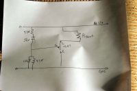
 testing the igbt shunt regulator testing the igbt shunt regulator
|
|
|
IamSmooth
|
|
Mon Dec 08 2008, 02:12AM
|

|
|
 Registered Member #190
Joined: Fri Feb 17 2006, 12:00AM
Location:
Posts: 1567
|
I was testing the shunt regulator and it was doing well. The Rshunt is 8.3 ohms. I was increasing the voltage with a variac and did not exceed 100v. Where I have the IGBT on the schematic it is really 4 in parallel and can handle 600W.
Once I exceed about 60v the voltage would not increase as I increased the variac. I could see the ammeter needle oscillate around 7 or 8A. I turned the system off and tried it again. This time the CE path was completely open. I guess it is latched. I don't know if I fried the chips or if I have to do something to get it back to the normal state. Any help? What can I do to prevent this?

|
|
Back to top
|
|
|
HV Enthusiast
|
|
 Registered Member #15
Joined: Thu Feb 02 2006, 01:11PM
Location:
Posts: 3068
|
Why are you using an IGBT for a linear application? Although it will work, they are generally poorly suited for linear applications and better for switching applications.
I would use a MOSFET.
|
|
Back to top
|
|
|
IamSmooth
|
|
 Registered Member #190
Joined: Fri Feb 17 2006, 12:00AM
Location:
Posts: 1567
|
I'm just experimenting right now. I have MOSFETs for the application, too.
That being said, is there any way to fix my problem with the IGBTs? How would I prevent this in the future?
|
|
Back to top
|
|
Moderator(s): Chris Russell, Noelle, Alex, Tesladownunder, Dave Marshall, Dave Billington, Bjørn, Steve Conner, Wolfram, Kizmo, Mads Barnkob
|
|
Powered by e107 Forum System
|

