If you need assistance, please send an email to forum at 4hv dot org. To ensure your email is not marked as spam, please include the phrase "4hv help" in the subject line. You can also find assistance via IRC, at irc.shadowworld.net, room #hvcomm.
Support 4hv.org!
Donate:
4hv.org is hosted on a dedicated server. Unfortunately, this server costs and we rely on the help of site members to keep 4hv.org running. Please consider donating. We will place your name on the thanks list and you'll be helping to keep 4hv.org alive and free for everyone. Members whose names appear in red bold have donated recently. Green bold denotes those who have recently donated to keep the server carbon neutral.
Special Thanks To:
Aaron Holmes
Aaron Wheeler
Adam Horden
Alan Scrimgeour
Andre
Andrew Haynes
Anonymous000
asabase
Austin Weil
barney
Barry
Bert Hickman
Bill Kukowski
Blitzorn
Brandon Paradelas
Bruce Bowling
BubeeMike
Byong Park
Cesiumsponge
Chris F.
Chris Hooper
Corey Worthington
Derek Woodroffe
Dalus
Dan Strother
Daniel Davis
Daniel Uhrenholt
datasheetarchive
Dave Billington
Dave Marshall
David F.
Dennis Rogers
drelectrix
Dr. John Gudenas
Dr. Spark
E.TexasTesla
eastvoltresearch
Eirik Taylor
Erik Dyakov
Erlend^SE
Finn Hammer
Firebug24k
GalliumMan
Gary Peterson
George Slade
GhostNull
Gordon Mcknight
Graham Armitage
Grant
GreySoul
Henry H
IamSmooth
In memory of Leo Powning
Jacob Cash
James Howells
James Pawson
Jeff Greenfield
Jeff Thomas
Jesse Frost
Jim Mitchell
jlr134
Joe Mastroianni
John Forcina
John Oberg
John Willcutt
Jon Newcomb
klugesmith
Leslie Wright
Lutz Hoffman
Mads Barnkob
Martin King
Mats Karlsson
Matt Gibson
Matthew Guidry
mbd
Michael D'Angelo
Mikkel
mileswaldron
mister_rf
Neil Foster
Nick de Smith
Nick Soroka
nicklenorp
Nik
Norman Stanley
Patrick Coleman
Paul Brodie
Paul Jordan
Paul Montgomery
Ped
Peter Krogen
Peter Terren
PhilGood
Richard Feldman
Robert Bush
Royce Bailey
Scott Fusare
Scott Newman
smiffy
Stella
Steven Busic
Steve Conner
Steve Jones
Steve Ward
Sulaiman
Thomas Coyle
Thomas A. Wallace
Thomas W
Timo
Torch
Ulf Jonsson
vasil
Vaxian
vladi mazzilli
wastehl
Weston
William Kim
William N.
William Stehl
Wesley Venis
The aforementioned have contributed financially to the continuing triumph of 4hv.org. They are deserving of my most heartfelt thanks.
Registered Member #76
Joined: Thu Feb 09 2006, 10:04AM
Location: Hemer, Germany
Posts: 458
Since my work became very popular here in germany within the last few months, i got some orders for building such musical drsstcs for theatres and so on. i want to share my work with others here and want to show you my latest drsstc work to inspire and to make people think about their own circuits and how to make it better.
The so called "X-Drive" driver is based on my older designs which are very reliable. one drsstc with this driver i build for a big company here in germany is lasting some 200hours of service with no problems. cause im not out for long discharges but reliability i tried to improve the overcurrent protection circuits etc.
cause i wanted to share my work with drsstc beginners too, i started thinking about the layout of such a driver and how to make it "bulletproof" and easy to build and adjust.
basically you have a "main board" with all components on it like on every other drsstc driver. and then you have 3 component plugs to install the components you want. the driver itself works without this components installed except the feedback board. so anyone can decide if he needs a overcurrent protection at all etc..
the driver is really straight forward
and here are the components Overcurrent protection and bargraph for a maximum current you can adjust. with the jumpers on the board you can adjust the max current you want from 50 to 500A in my case-
Primary feedback component Feedback and overcurrent CT and rectifier for the ocd ct on one board. just plug it in you primary circuit and youve done.
and because every new drsstc, especially one build for a client, needs a control unit, i started to build one.
This control unit has everything you want. special thanks here to steve conner and his solid state variac. sorry steve, but i changed your circuit to something i can call reliable. did last forever to adjust and find some bugs...
with this unit you can control the voltage of the little beast and everything else. my new so called "digidmod4.2" modulator is build in which makes the drsstc an allrounder. you can control the drsstc with single instruments like a keyboard or an e-guitar. a new feature can make you control the drsstc by voice. the amplitude of the incoming audio signal controls the on time. as the amplitude increases, the on time increases too. every signal higher than 1khz is divided by 2 to stay below the 1khz at any time. a pwm regulation controls the incoming frequency and the adjusted on time in realtime. if the frequency is getting higher, the on time decreases to prevent the fuse or the bridge from blowing up by to much current. the inbuild "normal" modulator can help by adjusting the coil and is activated by a switch. basically these modulator is conceived to control the drsstc with an ipod, but of course you can use every other analog audio source like a laptop or a cell phone or whatever you want. basically you drive the modulator with sinusodial signals, but you can even use square or triangle or sawtooth or mixed signals. the build in adjustable lowpass filter can help you by sorting out some "parts" of an audiosource you dont want to be modulated at all.
the control unit is connected via 2 cables to the drsstc. the optical toslink connection is to guarantee the highest possible safety for the user. the second cable is the power chord where you can control the driver and the voltage on the bridge etc.
Registered Member #30
Joined: Fri Feb 03 2006, 10:52AM
Location: Glasgow, Scotland
Posts: 6706
Cool Which solid-state variac circuit was it, and OMGplz can we see the improved version?
The bugs I'm aware of are: Both circuits lacked a soft-start, and the second one would sometimes get confused and pop the breaker at start-up, even if you did remember to turn the knob down to zero. I think it was due to phase shift caused by inrush in the control transformer (that provides the phase reference as well as powering the circuit) and I fixed it by connecting a capacitor in series with the primary.
The only reason I made the second one was that it can be remote controlled by a DC voltage. The first one is controlled by a variable resistance.
Registered Member #989
Joined: Sat Sept 08 2007, 02:15AM
Location: São Paulo, Brazil
Posts: 476
That is a great work reaching! My DRSSTC was based in your smallest coil schematic, but since I was increasing the power, I was need to change it a bit. But very good work! Keep working good!
Registered Member #76
Joined: Thu Feb 09 2006, 10:04AM
Location: Hemer, Germany
Posts: 458
@ Steve i didnt change much.. i used your second design which is voltage controlled. i left out the voltage gain pot of 100k which is shown in your shematic. i just used a 10k pot with 10k current limit resistor to regulate from 0 to 15 volt. that is my "Volt_F" as known in your shematic. to prevent the fuse from blowing up even if the pot is half or full power, i added a simple rc time constant. i changed the value of the rfi filter cap from 10n to 100µ, so even if the pot is set up full, the cap needs some seconds to get the full voltage. youll get a soft increase of voltage and so on a soft increase of voltage on the output too.,
i changed the value of the unknown primary L to 250µH and lowered the capacitance of the 100nF cap to 33n.
Registered Member #76
Joined: Thu Feb 09 2006, 10:04AM
Location: Hemer, Germany
Posts: 458
Finally some more pics. i want to get the whole coil finished within a few days. theres not much to do left. primary coil, secondary and finally the toroid and some wiring left. i think the coil is ready in some days.
Registered Member #56
Joined: Thu Feb 09 2006, 05:02AM
Location: Southern Califorina, USA
Posts: 2445
Pretty slick!
Can't wait to see it in action...
one thing I might comment on, when you put galleries together its works 100x better to put actual thumbnail sized pictures in for the thumbnails instead of the full several MB picture that and a resize tag.
Registered Member #76
Joined: Thu Feb 09 2006, 10:04AM
Location: Hemer, Germany
Posts: 458
Finished the primary coil today and the whole coil is coming out nicely. i cant wait to get the secondary finished and to prepare for the first tests. hopefully tommorow
Registered Member #76
Joined: Thu Feb 09 2006, 10:04AM
Location: Hemer, Germany
Posts: 458
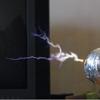
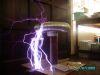
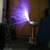
Finished the Coil today and did first tests.
Cause this coil have to be reliable rather than anything else, the output might be a little pitty for someone, but for a coupling lower than .12 , primary current of around 300 to 350A and 230v dc with less than 3,5Amps the output is enough to impress someone.
For sure this test was done with my new control box including steves solid state variac and my new digidmodV4.2 universal modulator. for the first light i thought it would be better to test with the inbuild standard interrupter, but for sure i will post some new vids with music...
This site is powered by e107, which is released under the GNU GPL License. All work on this site, except where otherwise noted, is licensed under a Creative Commons Attribution-ShareAlike 2.5 License. By submitting any information to this site, you agree that anything submitted will be so licensed. Please read our Disclaimer and Policies page for information on your rights and responsibilities regarding this site.


 X-Drive, and a new singing Teslacoil


 Which solid-state variac circuit was it, and OMGplz can we see the improved version?