If you need assistance, please send an email to forum at 4hv dot org. To ensure your email is not marked as spam, please include the phrase "4hv help" in the subject line. You can also find assistance via IRC, at irc.shadowworld.net, room #hvcomm.
Support 4hv.org!
Donate:
4hv.org is hosted on a dedicated server. Unfortunately, this server costs and we rely on the help of site members to keep 4hv.org running. Please consider donating. We will place your name on the thanks list and you'll be helping to keep 4hv.org alive and free for everyone. Members whose names appear in red bold have donated recently. Green bold denotes those who have recently donated to keep the server carbon neutral.
Special Thanks To:
Aaron Holmes
Aaron Wheeler
Adam Horden
Alan Scrimgeour
Andre
Andrew Haynes
Anonymous000
asabase
Austin Weil
barney
Barry
Bert Hickman
Bill Kukowski
Blitzorn
Brandon Paradelas
Bruce Bowling
BubeeMike
Byong Park
Cesiumsponge
Chris F.
Chris Hooper
Corey Worthington
Derek Woodroffe
Dalus
Dan Strother
Daniel Davis
Daniel Uhrenholt
datasheetarchive
Dave Billington
Dave Marshall
David F.
Dennis Rogers
drelectrix
Dr. John Gudenas
Dr. Spark
E.TexasTesla
eastvoltresearch
Eirik Taylor
Erik Dyakov
Erlend^SE
Finn Hammer
Firebug24k
GalliumMan
Gary Peterson
George Slade
GhostNull
Gordon Mcknight
Graham Armitage
Grant
GreySoul
Henry H
IamSmooth
In memory of Leo Powning
Jacob Cash
James Howells
James Pawson
Jeff Greenfield
Jeff Thomas
Jesse Frost
Jim Mitchell
jlr134
Joe Mastroianni
John Forcina
John Oberg
John Willcutt
Jon Newcomb
klugesmith
Leslie Wright
Lutz Hoffman
Mads Barnkob
Martin King
Mats Karlsson
Matt Gibson
Matthew Guidry
mbd
Michael D'Angelo
Mikkel
mileswaldron
mister_rf
Neil Foster
Nick de Smith
Nick Soroka
nicklenorp
Nik
Norman Stanley
Patrick Coleman
Paul Brodie
Paul Jordan
Paul Montgomery
Ped
Peter Krogen
Peter Terren
PhilGood
Richard Feldman
Robert Bush
Royce Bailey
Scott Fusare
Scott Newman
smiffy
Stella
Steven Busic
Steve Conner
Steve Jones
Steve Ward
Sulaiman
Thomas Coyle
Thomas A. Wallace
Thomas W
Timo
Torch
Ulf Jonsson
vasil
Vaxian
vladi mazzilli
wastehl
Weston
William Kim
William N.
William Stehl
Wesley Venis
The aforementioned have contributed financially to the continuing triumph of 4hv.org. They are deserving of my most heartfelt thanks.
Registered Member #952
Joined: Mon Aug 13 2007, 11:07AM
Location: Finland
Posts: 388
I thought about modding an ATX PSU for powering small SSTCs. So: lets say the +12V rail can supply 18 amps and the -12V rail 1 amp. If I combine them for 24V, how much current will I be able to draw?
Also another question: would those PSUs have any built-in RFI filter? I mean, those SMPS generate quite a lot of RFI, could there be any kind of filter on the ground side that could be also useful for grounding tesla coils?
Registered Member #152
Joined: Sun Feb 12 2006, 03:36PM
Location: Czech Rep.
Posts: 3384
spark wrote ...
I thought about modding an ATX PSU for powering small SSTCs. So: lets say the +12V rail can supply 18 amps and the -12V rail 1 amp. If I combine them for 24V, how much current will I be able to draw?
The answer is one amp. IIRC there was a thread on SMPS moddins so maybe searching is worth a try.
Registered Member #30
Joined: Fri Feb 03 2006, 10:52AM
Location: Glasgow, Scotland
Posts: 6706
Hi peoples
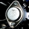
The answer is indeed 1 amp. But I think it would be easy enough to change that. If I remember right how these things work, the -12V comes off the same winding of heavy wire on the transformer as the +12V, but it goes through weedy small diodes and, IIRC, a -12V regulator. On the other hand the +12V goes through a heavy-duty Schottky dual diode, and a winding on the output filter choke (the large yellow toroid with several different wires wound on it)
You could fit bigger diodes, bypass the regulator, and add an extra winding on the output filter choke for your new -12V output, and theoretically get plenty of current at 24V. You'd probably need a good deal of electronics skill to make it work, though.
Yes, SMPS should have RFI filters on both input and output.
Registered Member #1107
Joined: Thu Nov 08 2007, 10:09PM
Location:
Posts: 792
Steve Conner wrote ...
Hi peoples
The answer is indeed 1 amp. But I think it would be easy enough to change that. If I remember right how these things work, the -12V comes off the same winding of heavy wire on the transformer as the +12V, but it goes through weedy small diodes and, IIRC, a -12V regulator. On the other hand the +12V goes through a heavy-duty Schottky dual diode, and a winding on the output filter choke (the large yellow toroid with several different wires wound on it)
You could fit bigger diodes, bypass the regulator, and add an extra winding on the output filter choke for your new -12V output, and theoretically get plenty of current at 24V. You'd probably need a good deal of electronics skill to make it work, though.
Yes, SMPS should have RFI filters on both input and output.
Yes Steve you are correct the +12v goes through a heatsinked double diode and the -12v goes through small 1A diodes so what i would do and i actually am going to do this myself is just replace the small diodes with big beefy 6A ones. also i dont see why i would need to put a extra winding on the output choke because they are all the same.
Registered Member #1232
Joined: Wed Jan 16 2008, 10:53PM
Location: Doon tha Toon!
Posts: 881
The existing wire for the -12V winding on the buck choke is likely of insufficient thickness to support 6 amps. Remember copper losses are proportional to I-squared. So pushing 6 amps through a winding designed to carry 1, will make it run 36 times hotter.
When you re-wind the -12V buck choke winding, make sure you wind it in the same direction as the original winding. So that it adds to the +12V buck inductance, not cancels it out!
Registered Member #89
Joined: Thu Feb 09 2006, 02:40PM
Location: Zadar, Croatia
Posts: 3145
I didn't remember ever seeing -12V regulator, -12V is taken from same winding and as you guys said thin wire on the buck choke, then to additional ferrite inductor and filter caps.
In order to get more power you (in most cases I know) need to replace the diodes, the choke winding and output ferrite inductor (which is pretty thin wire to).
I'd advise to replace the electrolytic caps too since ones installed are quite small, and you'll have to replace all caps anyway if you are going to boost the output voltage like Jan.
I've modded an ATX supply like that to output about +-20V, and it works pretty fine except I get odd audible sounds from the supply if I try to regulate the outputs significantly under the rated (+-12V) output voltages at low output powers, like the supply is oscillating, but this done no harm yet. At heavier load (10..15W) it mostly stops, but couldn't get rid of it (tried adjusting the feedback compensation network, shielding the potentiometer leads, reducing potentiometer resistance to minimum and etc.)
Registered Member #95
Joined: Thu Feb 09 2006, 04:57PM
Location: Norway
Posts: 1308
Marko wrote ...
I've modded an ATX supply like that to output about +-20V, and it works pretty fine except I get odd audible sounds from the supply if I try to regulate the outputs significantly under the rated (+-12V) output voltages at low output powers, like the supply is oscillating, but this done no harm yet. At heavier load (10..15W) it mostly stops, but couldn't get rid of it (tried adjusting the feedback compensation network, shielding the potentiometer leads, reducing potentiometer resistance to minimum and etc.)
I experience the exact same thing with my bench smps, but I don't know what causes it either. It sounds like ticking/crackling coming from the transformer.
Registered Member #1107
Joined: Thu Nov 08 2007, 10:09PM
Location:
Posts: 792
i tried to rewind the choke and it turns out that i can only wind 12 turns of heavier wire than the 20 turns that i removed of the thinner wire and i just wanted to know if this is a problem or not.
Registered Member #1232
Joined: Wed Jan 16 2008, 10:53PM
Location: Doon tha Toon!
Posts: 881
SMPSU feedback compensation is a big and complicated subject.
If you try to decrease the regulated output of an ATX power supply by more than 50%, by increasing the amount of voltage feedback, then you will most likely make the control loop oscillate. When you increase the feedback you are not only lowering the setpoint (decreasing the obtained output voltage) but you are also increasing something called loop-gain.
Loop gain is what stabilises the power supply and makes it regulate the output within a tight spec, removing ripple and loading effects, provided its value is right. However if the loop gain is high enough at frequencies where there is sufficient phase-shift around the feedback loop the supply will become unstable and eventually oscillate. (The main cause of the phase shift is the LC filter at the output of the supply.) This usually manifests itself as the output voltage repeatedly slamming between zero and about twice the intended output voltage at some frequency in the kilohertz - Not good, as the overvoltage and high ripple current can sometimes cause marginally rated electrolytics to vent, as well as obviously damaging anything sensitive that the unit is supplying power to.
If you are really interested in this stuff i'd recommend a google search for terms like "buck type III compensation". It is a complicated and messy subject involving bode-plots and gets mathematical very quickly. If you think a "pole" is something that holds up a tent, be prepared for a difficult read. Even for hardened power electronics engineers control loop compensation can still be the cause of some serious head-scratching.
This site is powered by e107, which is released under the GNU GPL License. All work on this site, except where otherwise noted, is licensed under a Creative Commons Attribution-ShareAlike 2.5 License. By submitting any information to this site, you agree that anything submitted will be so licensed. Please read our Disclaimer and Policies page for information on your rights and responsibilities regarding this site.


 ATX PSU question