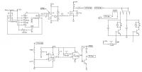
 New Coilgun Schematic New Coilgun Schematic
|
|
|
EDY19
|
|
Thu Jan 10 2008, 06:39AM
|

|
|
 Registered Member #105
Joined: Thu Feb 09 2006, 08:54PM
Location:
Posts: 408
|
Well, here it goes- my first go at a nice formal coilgun. This schematic has none of the coil details or capacitors worked out, however I thought i would post my first design for some constructive criticism. The second SCR gate will be optically triggered. The boost converter is in the upper right, with the UCC enable connected to the output of the AND gate - with the charge switch and the output from the comparator as the AND'ed entities. While the bank is under 400V and the switch is pressed, the boost converter will be on and the charging relay activated, effectively charging both banks in parallel to ensure the same voltage across them (there will be metering on both banks to monitor voltage). There is also a capacitor from the output of the AND gate to ground to delay the enable pin on the boost converter, so the bank is guaranteed to be connected before the boost is turned on. Please comment!!

|
|
Back to top
|
|
Moderator(s): Chris Russell, Noelle, Alex, Tesladownunder, Dave Marshall, Dave Billington, Bjørn, Steve Conner, Wolfram, Kizmo, Mads Barnkob
|
|
Powered by e107 Forum System
|

