If you need assistance, please send an email to forum at 4hv dot org. To ensure your email is not marked as spam, please include the phrase "4hv help" in the subject line. You can also find assistance via IRC, at irc.shadowworld.net, room #hvcomm.
Support 4hv.org!
Donate:
4hv.org is hosted on a dedicated server. Unfortunately, this server costs and we rely on the help of site members to keep 4hv.org running. Please consider donating. We will place your name on the thanks list and you'll be helping to keep 4hv.org alive and free for everyone. Members whose names appear in red bold have donated recently. Green bold denotes those who have recently donated to keep the server carbon neutral.
Special Thanks To:
Aaron Holmes
Aaron Wheeler
Adam Horden
Alan Scrimgeour
Andre
Andrew Haynes
Anonymous000
asabase
Austin Weil
barney
Barry
Bert Hickman
Bill Kukowski
Blitzorn
Brandon Paradelas
Bruce Bowling
BubeeMike
Byong Park
Cesiumsponge
Chris F.
Chris Hooper
Corey Worthington
Derek Woodroffe
Dalus
Dan Strother
Daniel Davis
Daniel Uhrenholt
datasheetarchive
Dave Billington
Dave Marshall
David F.
Dennis Rogers
drelectrix
Dr. John Gudenas
Dr. Spark
E.TexasTesla
eastvoltresearch
Eirik Taylor
Erik Dyakov
Erlend^SE
Finn Hammer
Firebug24k
GalliumMan
Gary Peterson
George Slade
GhostNull
Gordon Mcknight
Graham Armitage
Grant
GreySoul
Henry H
IamSmooth
In memory of Leo Powning
Jacob Cash
James Howells
James Pawson
Jeff Greenfield
Jeff Thomas
Jesse Frost
Jim Mitchell
jlr134
Joe Mastroianni
John Forcina
John Oberg
John Willcutt
Jon Newcomb
klugesmith
Leslie Wright
Lutz Hoffman
Mads Barnkob
Martin King
Mats Karlsson
Matt Gibson
Matthew Guidry
mbd
Michael D'Angelo
Mikkel
mileswaldron
mister_rf
Neil Foster
Nick de Smith
Nick Soroka
nicklenorp
Nik
Norman Stanley
Patrick Coleman
Paul Brodie
Paul Jordan
Paul Montgomery
Ped
Peter Krogen
Peter Terren
PhilGood
Richard Feldman
Robert Bush
Royce Bailey
Scott Fusare
Scott Newman
smiffy
Stella
Steven Busic
Steve Conner
Steve Jones
Steve Ward
Sulaiman
Thomas Coyle
Thomas A. Wallace
Thomas W
Timo
Torch
Ulf Jonsson
vasil
Vaxian
vladi mazzilli
wastehl
Weston
William Kim
William N.
William Stehl
Wesley Venis
The aforementioned have contributed financially to the continuing triumph of 4hv.org. They are deserving of my most heartfelt thanks.
Registered Member #3429
Joined: Sun Nov 21 2010, 02:04AM
Location: Minnesota, USA
Posts: 288
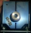
Hey guys -- I pulled a ferrite transformer out of dead ultrasonic knife power supply, which I plan to re-use in a different circuit design. I used my digital LCR meter (Tonghui model TH2821B) to measure the windings, and I got some confusing inductance values. Refer to my picture of the transformer below (I added pin numbers for reference). There are two rows of pins. In one row, there is only one winding that goes to pin #5 and #6 in the picture. In the other row, there is a multi-tapped winding that goes to pins #1 through #4. I do not know which row is considered the primary, and which is considered the secondary, but it doesn't matter for the purpose of this post.
All inductance readings taken with meter set to 1KHz: Between pins #1 and #2 I measure 15mH. Between pins #2 and #3 I meause 195 uH Between pins #3 and #4 I measure 195 uH
So far, so good. But here's the strange part. When I meause the inductances across multiple taps, the inductance values do not make sense. I know that if you double the number of turns in an inductor, its inductance will increase by four times (am I right?). But in this case, the inductance values are MUCH higher than what seems reasonable. Can someone please explain why I'm getting these strange readings?
Between pins #1 and #2 I measure 15 mH (same as previous reading shown above). Between pins #1 and #3 I measure 20 mH (this doesn't make sense!) Between pins #1 and #4 I measure 24 mH (ditto!)
On the other row (pins #5 and #6) I measure 20 mH. (there is no connection to any other pins)
Registered Member #3414
Joined: Sun Nov 14 2010, 05:05PM
Location: UK
Posts: 4245
The only thing I can think of is that the series windings may be wound in opposing directions, which would lead to some unexpected readings, but this is only a wild guess.
Registered Member #3429
Joined: Sun Nov 21 2010, 02:04AM
Location: Minnesota, USA
Posts: 288
Ash Small wrote ...
The only thing I can think of is that the series windings may be wound in opposing directions, which would lead to some unexpected readings, but this is only a wild guess.
Ash -- I suppose that's possible, and I could confirm that by applying a signal across two of the pins, and looking at the phase relationship between the various windings. If the signal is 180 degrees out of phase between any two windings, then that would confirm your suspicion. I'll try that later tonight if/when I have time. Thanks for your reply!
Registered Member #3429
Joined: Sun Nov 21 2010, 02:04AM
Location: Minnesota, USA
Posts: 288
Experimentonomen wrote ...
Could be a centertappd winding + a feedback winding
Reverse engineer the rest of the circuit around the transformer.
I already know that it's a multi-tapped winding. I began to reverse-engineer the circuit, but it was taking way to much time so I gave up on it. I can tell, in general, that the ultrasonic knife circuit is basically a "Royer Oscillator" that uses a pair of NPN transistors (not mosfets) to drive the hand-held knife. It operates at approximately 40KHz and puts out 30 Watts of ultrasonic power. Rather than try to repair it, because there are too many burnt components, I'm going to use a basic ZVS circuit using a pair of high power mosfets.
Registered Member #543
Joined: Tue Feb 20 2007, 04:26PM
Location: UK
Posts: 4992
Inductance meter readings tend to be more dependent on the test frequency than we might hope for - and if only one test frequency is used, the readings can sometimes be very wrong indeed.
Your transformer is not pure L after all, but will also be home to a good deal of parasitic capacitance between layers and windings and so forth. The windings also have resistance, so there you have the famous triad of LCR whose impedance will vary and might even resonate according to the test frequency applied.
The permeability of the core will also vary according to the drive level and the applied frequency.
And don't forget that a high turns ratio will multiply error effects - including in an auto transformer where the effective primary and secondary are in series.
These are some explanations for anomalous inductance meter readings. In industry, inductance is often given with reference to a standard measuring device, such as the HP4342A Q meter for example, to create at least one fixed point in this ocean of variables that refuse to be pinned down.
Registered Member #3429
Joined: Sun Nov 21 2010, 02:04AM
Location: Minnesota, USA
Posts: 288
Proud Mary wrote ...
Inductance meter readings tend to be more dependent on the test frequency than we might hope for - and if only one test frequency is used, the readings can sometimes be very wrong indeed.
Your transformer is not pure L after all, but will also be home to a good deal of parasitic capacitance between layers and windings and so forth. The windings also have resistance, so there you have the famous triad of LCR whose impedance will vary and might even resonate according to the test frequency applied.
The permeability of the core will also vary according to the drive level and the applied frequency.
And don't forget that a high turns ratio will multiply error effects - including in an auto transformer where the effective primary and secondary are in series.
This are some explanations for anomalous inductance meter readings. In industry, inductance is often given with reference to a standard measuring device, such as the HP4342A Q meter, to create a fixed point in this ocean of variables that refuse to be pinned down.
Some good points, Proud Mary! Besides the fairly new digital LCR meter, I also own an old GenRad analog LCR bridge that I'll run the same tests with. It requires a number of size D batteries to power it, which I'll have to purchase, and then I'll see if the analog bridge shows me different results from the digital meter. I'll let you guys know how that turns out.
Registered Member #3429
Joined: Sun Nov 21 2010, 02:04AM
Location: Minnesota, USA
Posts: 288
UPDATE: I ran the same inductance checks with my old GenRad "Impedance Bridge" and I got nearly identical results as I did with my digital LCR meter! There was only a slight difference of maybe 1 percent, which is probably due to the GenRad not being calibrated for many years. So, I confirmed that the strange readings were not due to some funky artifact of the meter.
I guess at this point I'm not going to worry about it because I may not use this transformer anyways. It was just the strange readings that I wanted to get resolved. I'm now starting to think that the basic problem is due to all the variables that Proud Mary had mentioned, and I may just be chasing my tail if I continue to pursue a simple, concrete answer when there is none!
This site is powered by e107, which is released under the GNU GPL License. All work on this site, except where otherwise noted, is licensed under a Creative Commons Attribution-ShareAlike 2.5 License. By submitting any information to this site, you agree that anything submitted will be so licensed. Please read our Disclaimer and Policies page for information on your rights and responsibilities regarding this site.


 Strange inductance readings