 Registered Member #49
Joined: Thu Feb 09 2006, 04:05AM
Location: Bigass Pile of Penguins
Posts: 362
|
Something a little different, but quick and rewarding should you wish to duplicate it.
A solid of constant width is a solid body that, when trapped between two parallel planes, measures the same width for all orientations. A circle is an obvious example, but more complex arrangements are possible.
Youtube has a video of several such solids showing how cool they are and potentially fun to fool around with on one's desk: 
The Reuleaux triangle is a 2d example:

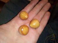
A 3d example can be constructed by revolving the Reuleaux triangle around the axis of symmetry that passes through any vertex, producing an acorn-like shape. The same applies to any polygon with an odd number of vertexes and "Reuleaux" geometry.
Note many other designs satisfy the criteria - sharp corners or even symmetry are not required. Rounded corners are convenient from a manufacturing standpoint.

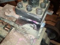
I cut a piece of steel on my CNC mill and then popped it into the lathe to cut such marbles out of scrap wood - this one was done for a 3-sided solid obviously:

And the finished results:

Should you wish to duplicate, here is a matlab script that a) generates 2d polygons of constant width with any number of sides and any corner radius, and b) outputs Gcode toolpaths to create the cutting tool (or even program your lathe directly, should it be so equipped).
%CWS generator
%Andrew Maurer
clear all
close all

sides=3  %Must be odd integer
rc=0.125 %Corner/cutter RADIUS
r=1      %"Statutory" width of solid

for i=1:sides
   centers(i,:)=[(r/2-rc)*sin(2*pi*i/sides) (r/2-rc)*cos(2*pi*i/sides)]
end
plot(centers(:,1),centers(:,2), '*')
hold on

dtex=norm(centers(1,:)-centers(floor(sides/2)+1,:))

axis square
axis equal
grid on

k=1
for i=1:sides
   for t=0:ceil(r/rc)/2:floor(180/sides)
       theta = 360*i/sides-90/sides+t
       plot(centers(i,1)+rc*sin(theta*2*pi/360), centers(i,2)+rc*cos(theta*2*pi/360),'.r')
       ptcld(k,:)=[centers(i,1)+rc*sin(theta*2*pi/360), centers(i,2)+rc*cos(theta*2*pi/360)]
       k=k+1
   end
   for t=0:floor(180/sides)
       i2=i+ceil(sides/2)
       if i2>sides
           i2=i2-sides;
       end
       theta = 360*i2/sides-90/sides+t
       plot(centers(i2,1)+(dtex+rc)*sin(theta*2*pi/360+pi), centers(i2,2)+(dtex+rc)*cos(theta*2*pi/360+pi),'.g')
       ptcld(k,:)=[centers(i2,1)+(dtex+rc)*sin(theta*2*pi/360+pi), centers(i2,2)+(dtex+rc)*cos(theta*2*pi/360+pi)]
       k=k+1
   end
end

figure
i=1
while i<size(ptcld,1)
   if ptcld(i,1)<0
       ptcld(i,:)=[]
   else
       i=i+1
   end

end

vline=[0 max(ptcld(:,2))+r/2]
for i=2:100
   vline(i,:)=[vline(i-1,1) vline(i-1,2)-r/200]
end
vline2=[0 min(ptcld(:,2))]
for i=2:100
   vline2(i,:)=[vline2(i-1,1) vline2(i-1,2)-r/200]
end

ptcld=[vline;ptcld;vline2]
ptcld=sortrows(ptcld,2)

plot(ptcld(:,1),ptcld(:,2),'b')

axis square
axis equal


k=1
for i=min(ptcld(:,2)):r/200:max(ptcld(:,2))
   y=i;
   [poo mindex]=min(abs(ptcld(:,2)-y));
   x=ptcld(mindex,1);
   d=0;
   while d<rc
       d=99e9;
       for i=1:size(ptcld,1)
          dt=norm([x y]-ptcld(i,:));
          if dt<d
              d=dt;
          end
       end
       if d<rc;
        x=x-r/500;
       end
   end
   hold on
   plot(x,y,'r*');
   %drawnow
   cnc(k,:)=[x y];
   k=k+1;
end

fid = fopen('out.iso', 'w');
for i=1:size(cnc,1)
fprintf(fid, 'G01 X%6.6f Y%6.6f F1\n', cnc(i,1), cnc(i,2));
end
fclose(fid);
Here's an example output for a constant-width pentagon w/ "width" = 1, and 0.125 radius corners.

The toolpath output is very basic - just a single profile pass along the "edge" of a cutting tool as shown. In blue is the profile of the tool to be created. The mill toothpath is shown in red. Note that the tool diameter is assumed to be the same as the diameter of the corners - I used a 1/4" endmill in the photos shown.

|

