If you need assistance, please send an email to forum at 4hv dot org. To ensure your email is not marked as spam, please include the phrase "4hv help" in the subject line. You can also find assistance via IRC, at irc.shadowworld.net, room #hvcomm.
Support 4hv.org!
Donate:
4hv.org is hosted on a dedicated server. Unfortunately, this server costs and we rely on the help of site members to keep 4hv.org running. Please consider donating. We will place your name on the thanks list and you'll be helping to keep 4hv.org alive and free for everyone. Members whose names appear in red bold have donated recently. Green bold denotes those who have recently donated to keep the server carbon neutral.
Special Thanks To:
Aaron Holmes
Aaron Wheeler
Adam Horden
Alan Scrimgeour
Andre
Andrew Haynes
Anonymous000
asabase
Austin Weil
barney
Barry
Bert Hickman
Bill Kukowski
Blitzorn
Brandon Paradelas
Bruce Bowling
BubeeMike
Byong Park
Cesiumsponge
Chris F.
Chris Hooper
Corey Worthington
Derek Woodroffe
Dalus
Dan Strother
Daniel Davis
Daniel Uhrenholt
datasheetarchive
Dave Billington
Dave Marshall
David F.
Dennis Rogers
drelectrix
Dr. John Gudenas
Dr. Spark
E.TexasTesla
eastvoltresearch
Eirik Taylor
Erik Dyakov
Erlend^SE
Finn Hammer
Firebug24k
GalliumMan
Gary Peterson
George Slade
GhostNull
Gordon Mcknight
Graham Armitage
Grant
GreySoul
Henry H
IamSmooth
In memory of Leo Powning
Jacob Cash
James Howells
James Pawson
Jeff Greenfield
Jeff Thomas
Jesse Frost
Jim Mitchell
jlr134
Joe Mastroianni
John Forcina
John Oberg
John Willcutt
Jon Newcomb
klugesmith
Leslie Wright
Lutz Hoffman
Mads Barnkob
Martin King
Mats Karlsson
Matt Gibson
Matthew Guidry
mbd
Michael D'Angelo
Mikkel
mileswaldron
mister_rf
Neil Foster
Nick de Smith
Nick Soroka
nicklenorp
Nik
Norman Stanley
Patrick Coleman
Paul Brodie
Paul Jordan
Paul Montgomery
Ped
Peter Krogen
Peter Terren
PhilGood
Richard Feldman
Robert Bush
Royce Bailey
Scott Fusare
Scott Newman
smiffy
Stella
Steven Busic
Steve Conner
Steve Jones
Steve Ward
Sulaiman
Thomas Coyle
Thomas A. Wallace
Thomas W
Timo
Torch
Ulf Jonsson
vasil
Vaxian
vladi mazzilli
wastehl
Weston
William Kim
William N.
William Stehl
Wesley Venis
The aforementioned have contributed financially to the continuing triumph of 4hv.org. They are deserving of my most heartfelt thanks.
Registered Member #1034
Joined: Sat Sept 29 2007, 12:50PM
Location: Chillicothe, Ohio
Posts: 154
This Royer induction heater achieves a moderately high power level by using groups of 4 IRFP260 MOSFETs in parallel. The circuit is similar to Marko's Royer oscillator shown below except that each side uses four MOSFETs paralleled together with each MOSFET having it's own gate biasing circuit. The B+ voltage is 70 volts. I found that if I go much higher than that the efficiency starts going down and the MOSFETs become more prone to failure. Since I am using a higher B+ voltage I have changed the resistors in the gate biasing circuits from 470 ohms to 800 ohms.
The resonant frequency runs in the range of 40 to 60 KHZ depending on what work coil I am using. The tank circuit uses 24 .22uf capacitors in parallel for a total of 5.28 uf. They are Cornell Dubilier polypropylene capacitors rated for 1600 volts. I can leave the induction heater on for long periods of time and the capacitors will just get a little bit warm.
The power level depends on the work coil and the size of the object being heated and I am measuring input power here. With nothing at all in the work coil the machine consumes 700 Watts and if you load it much beyond 4KW it will stop oscillating and bad things can happen to the MOSFETs. Only ferrous metals will heat up red hot and other metals just get hot to the touch.
Registered Member #89
Joined: Thu Feb 09 2006, 02:40PM
Location: Zadar, Croatia
Posts: 3145
Haha, so you boxed it up... I honestly never intended this circuit to be used as a worktool as much as a curiosity for newbies (who always kept doing weird things with flyback cores and never getting it rigtht).
The obvious problems are the power supply as well as the instabilities in the circuit... diode voltage drop along with switching device forward voltage makes switching off very troubleosme at high voltages (I tried it with 1200V igbt's, and after some 150V it blew up)
Perhaps an IH like this could though eb used as a handy add-on for an arc welder.
Roger, ave you tried using a smaller work coil? That way you might be able to melt something instead of just heating huge pieces of metal red.
Also, you seem to have wiring gratuitously hanging everywhere... I'm usually not a parasitic inductance grandma, but your connections between mosfets and tank circuit could be having inductance significant in comparison to workcoil... make them coaxial or at least twist them together, if you can't shorten them... same applies for the gate drive section as well!
Registered Member #1034
Joined: Sat Sept 29 2007, 12:50PM
Location: Chillicothe, Ohio
Posts: 154
Marko, I have been thinking about making a smaller work coil. It would be cool to at least be able to get things white hot instead of red hot. There is a reason that I'm building this beyond the curiosity stage. If all goes well it will be used by some machinist for heat treating and silver soldering little pieces of carbide to steel bars.
As far as the wiring is concerned, I did try having more direct connections to the sources on the MOSFETs once but it wouldn't run that way and when it doesn't run everything goes up in smoke. I had to go back to connecting the source leads to the ground on the biasing boards. This circuit is very finicky about some things but once you get it right it is vary reliable.
Another thing I learned the hard way is not to use MOSFETs other than the IRFP260 or IRFP250 types even if they have higher ratings. At least not unless you really know what you are doing. They can be made to work but they won't work as well.
Registered Member #89
Joined: Thu Feb 09 2006, 02:40PM
Location: Zadar, Croatia
Posts: 3145
Hi roger
well, If I for any reason just had to do a high power this way, there's no way I'd do it without overcurrent protection. A simple shunt, LM311 and a NE555 could save countless mosfet lives not only in prototyping stage but as well as when the end user decides to place a too large workpiece into it so the circuit latches up and explodes.
Registered Member #162
Joined: Mon Feb 13 2006, 10:25AM
Location: United Kingdom
Posts: 3141
RogerInOhio a zvs running in zvs mode produces PI x Vsupply peak across each switch so it's not surprising that your transistors heat up with greater than 70 Vdc as 3.1416 x 70 = 220 V peak , IRFP260 Vds = 200 Vpk !!!! i.e. you need higher voltage rated transistors.
Registered Member #1034
Joined: Sat Sept 29 2007, 12:50PM
Location: Chillicothe, Ohio
Posts: 154
Since I went to using 8 MOSFETs I haven't blown any up yet from over loading but maybe I should have better over current protection than the fuses I am using.
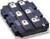
The transformer is from an old UPS system that was being scraped. I was lucky enough to get my hands on two of them. I will post a picture of the waveform below.
As for the MOSFETs, I have tried some that have a higher voltage ratting but nothing seems to work as well as the IRFP260. I guess I will have to wait for Marko to pioneer a circuit that uses IGTBs.
I just made a hot new video of the induction heater using a smaller work coil.
Registered Member #89
Joined: Thu Feb 09 2006, 02:40PM
Location: Zadar, Croatia
Posts: 3145
Hi guys
Well, I don't think I'll be pioneering this circuit with IGBT's any time soon unless someone pays me especially for it and organizes free time to do so!
Just to illustrate how bad the problem is - to run offline with 325VDC at least 1200V devices would be required. 1200V IGBT's have forward voltage drop of as much as 3-4V. Then consider the feedback diodes, which at this voltage rating might have over 2V drop too which in total is well over gate threshold voltage of the opposing igbt - meaning that it'll never actually fully turn off! I was surprised that the contraption worked at all for some time before blowing up at some 150V DC in or so.
Also, when I tried using UF4007's for feedback they blew up from recovery losses at just 100V in or so, and had to use two 600V 8A fast rectifiers in series which made the voltage drop even worse.
I think this is the same reason why lower RdsON mosfets work better in this circuit; they can turn off the gate of opposing mosfet harder and hence reduce the possibility of ringing from turning it back on (and degenerating into a parasitic oscillation which sends everything to oblivion)
The very topology of a current fed inverter is on the other hand very attractive for induction heater designs, especially at high frequencies where ZVS operation becomes useful as well as unitiy power factor from the inverter obtained with parallel resonant circuit (which isn't the case with LCLR)
The industrial standard for such an inverter would be a full bridge with PLL based controller, although I see no reason why wouldn't it work with push pull topology as long as you respect the device voltage ratings.
I see no reason why a well made direct feedback scheme with phase lead compensation wouldn't work as well, although it would be nowhere closely as simple as a good old royer oscillator and nobody would likely bother building it (instead of just copying kim ladha's or whoever's IH).
Registered Member #89
Joined: Thu Feb 09 2006, 02:40PM
Location: Zadar, Croatia
Posts: 3145
Inducktion wrote ...
Why not try to use those fancy SiC Schottky diodes? Their voltage drop should be really really small, correct?
Or maybe, instead of using diode feedback why not use some active gate driving techniques?
Well, it's the device voltage drop, not the diode drop that creates the most trouble.
I have tried feedback from an isolated winding but failed... at low power levels, I also made a circuit that combines diode feedback and feedback windings to reduce the pullup resistor losses, and it worked wonderfully although the diode problem remained.
I'm currently researching direct feedback approach with capacitive voltage divider (basically, making the gate a portion of tank capacitance) but it came with it's own set of problems too - bias on the gate seems to vary and equalizer resistors and zeners weren't as good at fixing it, not sure why. (btw, the idea works wonderfully when gate is connected directly to opposing drain and circuit is fed with small <6V voltages)
I was even wondering if it might be easier to replace igbt's with high power BJT's (like HOT's) since they are biased by current and could be much more easily set into linear region without tendency to blow up instantly (hopefully).
Ofcourse, a circuit like this should definitely be overcurrent protected well with transzorbs to absorb overvoltage when all devices are suddenly turned off... I've never seen people do this though and they just keep crying OMG this circuit sux I blew all 10 mosfets I had and mom give me no money :(
This site is powered by e107, which is released under the GNU GPL License. All work on this site, except where otherwise noted, is licensed under a Creative Commons Attribution-ShareAlike 2.5 License. By submitting any information to this site, you agree that anything submitted will be so licensed. Please read our Disclaimer and Policies page for information on your rights and responsibilities regarding this site.


 4KW Induction Heater