
4KW Induction Heater
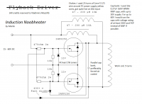
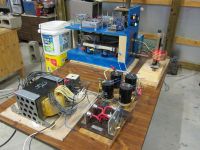
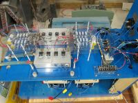
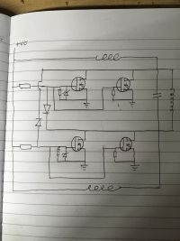
RogerInOhio, Sat Nov 26 2011, 04:38PMThis Royer induction heater achieves a moderately high power level by using groups of 4 IRFP260 MOSFETs in parallel. The circuit is similar to Marko's Royer oscillator shown below except that each side uses four MOSFETs paralleled together with each MOSFET having it's own gate biasing circuit. The B+ voltage is 70 volts. I found that if I go much higher than that the efficiency starts going down and the MOSFETs become more prone to failure. Since I am using a higher B+ voltage I have changed the resistors in the gate biasing circuits from 470 ohms to 800 ohms.
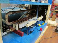
The resonant frequency runs in the range of 40 to 60 KHZ depending on what work coil I am using. The tank circuit uses 24 .22uf capacitors in parallel for a total of 5.28 uf. They are Cornell Dubilier polypropylene capacitors rated for 1600 volts. I can leave the induction heater on for long periods of time and the capacitors will just get a little bit warm.
The power level depends on the work coil and the size of the object being heated and I am measuring input power here. With nothing at all in the work coil the machine consumes 700 Watts and if you load it much beyond 4KW it will stop oscillating and bad things can happen to the MOSFETs. Only ferrous metals will heat up red hot and other metals just get hot to the touch.
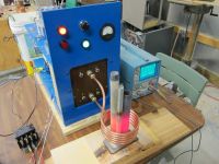
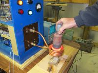
Re: 4KW Induction Heater
Marko, Sun Nov 27 2011, 02:26AM
Haha, so you boxed it up... I honestly never intended this circuit to be used as a worktool as much as a curiosity for newbies (who always kept doing weird things with flyback cores and never getting it rigtht).
The obvious problems are the power supply as well as the instabilities in the circuit... diode voltage drop along with switching device forward voltage makes switching off very troubleosme at high voltages (I tried it with 1200V igbt's, and after some 150V it blew up)
Perhaps an IH like this could though eb used as a handy add-on for an arc welder.
Roger, ave you tried using a smaller work coil? That way you might be able to melt something instead of just heating huge pieces of metal red.
Also, you seem to have wiring gratuitously hanging everywhere... I'm usually not a parasitic inductance grandma, but your connections between mosfets and tank circuit could be having inductance significant in comparison to workcoil... make them coaxial or at least twist them together, if you can't shorten them... same applies for the gate drive section as well!
marko
Re: 4KW Induction Heater
RogerInOhio, Sun Nov 27 2011, 02:15PM
Marko, I have been thinking about making a smaller work coil. It would be cool to at least be able to get things white hot instead of red hot. There is a reason that I'm building this beyond the curiosity stage. If all goes well it will be used by some machinist for heat treating and silver soldering little pieces of carbide to steel bars.
As far as the wiring is concerned, I did try having more direct connections to the sources on the MOSFETs once but it wouldn't run that way and when it doesn't run everything goes up in smoke. I had to go back to connecting the source leads to the ground on the biasing boards. This circuit is very finicky about some things but once you get it right it is vary reliable.
Another thing I learned the hard way is not to use MOSFETs other than the IRFP260 or IRFP250 types even if they have higher ratings. At least not unless you really know what you are doing. They can be made to work but they won't work as well.
Re: 4KW Induction Heater
Marko, Sun Nov 27 2011, 02:59PM
Hi roger
well, If I for any reason just had to do a high power this way, there's no way I'd do it without overcurrent protection. A simple shunt, LM311 and a NE555 could save countless mosfet lives not only in prototyping stage but as well as when the end user decides to place a too large workpiece into it so the circuit latches up and explodes.
Marko
Re: 4KW Induction Heater
Jrz126, Mon Nov 28 2011, 01:11PM
Looks great Roger.
Have any waveform pics? Where'd you get that boat anchor of transformer?
Jrz126, Mon Nov 28 2011, 01:11PM
Looks great Roger.
Have any waveform pics? Where'd you get that boat anchor of transformer?
Re: 4KW Induction Heater
Sulaiman, Mon Nov 28 2011, 01:28PM
RogerInOhio
a zvs running in zvs mode produces PI x Vsupply peak across each switch
so it's not surprising that your transistors heat up with greater than 70 Vdc
as 3.1416 x 70 = 220 V peak , IRFP260 Vds = 200 Vpk !!!!
i.e. you need higher voltage rated transistors.
Re: 4KW Induction Heater
RogerInOhio, Mon Nov 28 2011, 03:46PM
Since I went to using 8 MOSFETs I haven't blown any up yet from over loading but maybe I should have better over current protection than the fuses I am using.
The transformer is from an old UPS system that was being scraped. I was lucky enough to get my hands on two of them. I will post a picture of the waveform below.
As for the MOSFETs, I have tried some that have a higher voltage ratting but nothing seems to work as well as the IRFP260. I guess I will have to wait for Marko to pioneer a circuit that uses IGTBs.
I just made a hot new video of the induction heater using a smaller work coil.
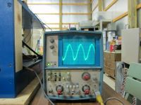


Re: 4KW Induction Heater
Marko, Mon Nov 28 2011, 08:11PM
Hi guys
Well, I don't think I'll be pioneering this circuit with IGBT's any time soon unless someone pays me especially for it and organizes free time to do so!
Just to illustrate how bad the problem is - to run offline with 325VDC at least 1200V devices would be required. 1200V IGBT's have forward voltage drop of as much as 3-4V. Then consider the feedback diodes, which at this voltage rating might have over 2V drop too which in total is well over gate threshold voltage of the opposing igbt - meaning that it'll never actually fully turn off! I was surprised that the contraption worked at all for some time before blowing up at some 150V DC in or so.
Also, when I tried using UF4007's for feedback they blew up from recovery losses at just 100V in or so, and had to use two 600V 8A fast rectifiers in series which made the voltage drop even worse.
I think this is the same reason why lower RdsON mosfets work better in this circuit; they can turn off the gate of opposing mosfet harder and hence reduce the possibility of ringing from turning it back on (and degenerating into a parasitic oscillation which sends everything to oblivion)
The very topology of a current fed inverter is on the other hand very attractive for induction heater designs, especially at high frequencies where ZVS operation becomes useful as well as unitiy power factor from the inverter obtained with parallel resonant circuit (which isn't the case with LCLR)
The industrial standard for such an inverter would be a full bridge with PLL based controller, although I see no reason why wouldn't it work with push pull topology as long as you respect the device voltage ratings.
I see no reason why a well made direct feedback scheme with phase lead compensation wouldn't work as well, although it would be nowhere closely as simple as a good old royer oscillator and nobody would likely bother building it (instead of just copying kim ladha's or whoever's IH).
Marko
Re: 4KW Induction Heater
Inducktion, Mon Nov 28 2011, 11:19PM
Why not try to use those fancy SiC Schottky diodes? Their voltage drop should be really really small, correct?
Or maybe, instead of using diode feedback why not use some active gate driving techniques?
Inducktion, Mon Nov 28 2011, 11:19PM
Why not try to use those fancy SiC Schottky diodes? Their voltage drop should be really really small, correct?
Or maybe, instead of using diode feedback why not use some active gate driving techniques?
Re: 4KW Induction Heater
Marko, Tue Nov 29 2011, 05:25AM
Well, it's the device voltage drop, not the diode drop that creates the most trouble.
I have tried feedback from an isolated winding but failed... at low power levels, I also made a circuit that combines diode feedback and feedback windings to reduce the pullup resistor losses, and it worked wonderfully although the diode problem remained.
I'm currently researching direct feedback approach with capacitive voltage divider (basically, making the gate a portion of tank capacitance) but it came with it's own set of problems too - bias on the gate seems to vary and equalizer resistors and zeners weren't as good at fixing it, not sure why. (btw, the idea works wonderfully when gate is connected directly to opposing drain and circuit is fed with small <6V voltages)
I was even wondering if it might be easier to replace igbt's with high power BJT's (like HOT's) since they are biased by current and could be much more easily set into linear region without tendency to blow up instantly (hopefully).
Ofcourse, a circuit like this should definitely be overcurrent protected well with transzorbs to absorb overvoltage when all devices are suddenly turned off... I've never seen people do this though and they just keep crying OMG this circuit sux I blew all 10 mosfets I had and mom give me no money :(
Cheers,
Marko
Marko, Tue Nov 29 2011, 05:25AM
Inducktion wrote ...
Why not try to use those fancy SiC Schottky diodes? Their voltage drop should be really really small, correct?
Or maybe, instead of using diode feedback why not use some active gate driving techniques?
Why not try to use those fancy SiC Schottky diodes? Their voltage drop should be really really small, correct?
Or maybe, instead of using diode feedback why not use some active gate driving techniques?
Well, it's the device voltage drop, not the diode drop that creates the most trouble.
I have tried feedback from an isolated winding but failed... at low power levels, I also made a circuit that combines diode feedback and feedback windings to reduce the pullup resistor losses, and it worked wonderfully although the diode problem remained.
I'm currently researching direct feedback approach with capacitive voltage divider (basically, making the gate a portion of tank capacitance) but it came with it's own set of problems too - bias on the gate seems to vary and equalizer resistors and zeners weren't as good at fixing it, not sure why. (btw, the idea works wonderfully when gate is connected directly to opposing drain and circuit is fed with small <6V voltages)
I was even wondering if it might be easier to replace igbt's with high power BJT's (like HOT's) since they are biased by current and could be much more easily set into linear region without tendency to blow up instantly (hopefully).
Ofcourse, a circuit like this should definitely be overcurrent protected well with transzorbs to absorb overvoltage when all devices are suddenly turned off... I've never seen people do this though and they just keep crying OMG this circuit sux I blew all 10 mosfets I had and mom give me no money :(
Cheers,
Marko
Re: 4KW Induction Heater
Tonskulus, Sun Dec 04 2011, 02:05PM
I wonder how would it be possible to heat up and melt non-ferrous metals using this circuit?
It looks like when in idle mode (empty work coil), there is not much tank current circulating there.
Its not frequency issue, my halfbridge igbt induction heater will melt non-ferrous coins or similar in seconds! Input power was around 2kW and frequency 50-70kHz.
aluminium coin:
http://www.youtube.com/user/tonskulus?feature=mhee#p/u/34/STVJOB7o9dI
I know, non ferrous metals require much more work coil current compared to ferrous metals like iron.
Difference is that iron has both, hysteresis losses and circulating current (resistive) losses while non-ferrous has only circulating current losses. Like aluminium, it is quite good conductor so lots of current is required.
Re: 4KW Induction Heater
Marko, Tue Dec 06 2011, 11:32AM
Hey guys
Tonskulus: Unlike series resonant or LCLR induction heaters, a current fed royer oscillator tends to hold constant voltage on the tank circuit, equal to pi*supply voltage. Since impedance of the tank is dominated by it's reactive components, the circulating current in it will approximately be equal to this voltage divided by the tank's characteristic impedance. And this is by no means a small figure, I seem to get close to 150A in my little royer induction heater just when it sits without workpiece.
When non-ferrous workpiece is inserted it tends to both decrease inductance and increase the loss in the tank, so current will go up slightly as well as get more into phase with voltage. I don't think this increase is very significant though compared to no-load current in the coil, even if the workpiece completely shadows the coil I don't believe it ever reaches 1.5 initial current or so.
It's true that non-ferrous metals (especially highly conductive ones) will represent a less of a load when put into work coil, but how fast you can melt them really depends on how much power you put into system! I was limited by quite smallish transformers I was using for my power supply.
The good thing about current fed oscillator is that it can't run away when not loaded with any workpiece - can be pretty much ran open loop unless you need special power regulation.
By the way, after some research I think it would be possible to implement an IH like this with big 1500V HOT's. Due to slowness of devices it would require high tank capacitance, on order of 100uF.
If someone is willing to donate me one of those 100uF 500A eurofarad caps which I can't get from ebay, I promise this will be the next thing I'll try
Marko
Marko, Tue Dec 06 2011, 11:32AM
Hey guys
Tonskulus: Unlike series resonant or LCLR induction heaters, a current fed royer oscillator tends to hold constant voltage on the tank circuit, equal to pi*supply voltage. Since impedance of the tank is dominated by it's reactive components, the circulating current in it will approximately be equal to this voltage divided by the tank's characteristic impedance. And this is by no means a small figure, I seem to get close to 150A in my little royer induction heater just when it sits without workpiece.
When non-ferrous workpiece is inserted it tends to both decrease inductance and increase the loss in the tank, so current will go up slightly as well as get more into phase with voltage. I don't think this increase is very significant though compared to no-load current in the coil, even if the workpiece completely shadows the coil I don't believe it ever reaches 1.5 initial current or so.
It's true that non-ferrous metals (especially highly conductive ones) will represent a less of a load when put into work coil, but how fast you can melt them really depends on how much power you put into system! I was limited by quite smallish transformers I was using for my power supply.
The good thing about current fed oscillator is that it can't run away when not loaded with any workpiece - can be pretty much ran open loop unless you need special power regulation.
By the way, after some research I think it would be possible to implement an IH like this with big 1500V HOT's. Due to slowness of devices it would require high tank capacitance, on order of 100uF.
If someone is willing to donate me one of those 100uF 500A eurofarad caps which I can't get from ebay, I promise this will be the next thing I'll try

Marko
Re: 4KW Induction Heater
Tonskulus, Tue Dec 06 2011, 03:15PM
Yes, that makes sense.
I never measured the actual current on my tank circuit, DC bus voltage was around 300V so ofcourse there will be much more tank current compared to a royer operating around 70Volts.
One solution would be heavy matching transformer, there will be power losses but some commerical induction heaters use this method. Yes, tank circuit is at primary side of transformer. Work coil is connected directly to the secondary.
Some vacuum tube oscillator type heaters used air cored matching transformers (I did that too). But it is totally different...
but the point is that matching transformers can be used anyway. Requires heavy windings/water cooling usually.
I need to try out that royer circuit if I can find a method for heating non-ferrous metals with minimal power losses :)
Maybe a challenge for us!
Re: 4KW Induction Heater
RogerInOhio, Tue Dec 06 2011, 03:44PM
Marko, after doing some searching I think HOT must stand for horizontal output transistor and the ones I have found have kind of a low current rating. It seems like a tank circuit with a 100uF capacitor would have a low impedance even if the frequency was low. Would this be a Royer Oscillator or some other type of IH circuit?
On the subject of eddy currents, I have noticed that the work coil itself has significant eddy current losses. If I run my IH without water going though the tubing the work coil gets hot but the tubing going to the work coil stays cool. I guess that a work coil that used something like litz wire would be more efficient.
Re: 4KW Induction Heater
Marko, Tue Dec 06 2011, 08:08PM
Hi guys
Yes, HOT's stand for TV horizontal deflection transistors, and I thought their ratings would be too low until I saw some beefy ones for high-definition TV's ;)
And yes again, they would be used in a royer oscillator, in a classic configuration with feedback winding!
This one is rated 25A continuous, 50A peak and 1600Vce which should make it robust enough for the application.

2SC3998 is another nice one... if anyone finds a better transistor let me know!
Ofcourse there's a large chance this idea might not work at all, and I'd be just as happy if someone else tested it instead of me!
To keep the frequency low enough for operation of HOT's, I realized that quite large tank capacitance would be needed, on order of tens of uF... and those eurofarad caps just came to my mind as they seem useless for most other things (apart for decoupling on a monstrous boost or buck converter?)
I wouldn't likely be able to drive them to their full voltage ratings - but with 500A rms they would surely be a lot of fun anyway :)
Marko
Marko, Tue Dec 06 2011, 08:08PM
Hi guys
Yes, HOT's stand for TV horizontal deflection transistors, and I thought their ratings would be too low until I saw some beefy ones for high-definition TV's ;)
And yes again, they would be used in a royer oscillator, in a classic configuration with feedback winding!
This one is rated 25A continuous, 50A peak and 1600Vce which should make it robust enough for the application.

2SC3998 is another nice one... if anyone finds a better transistor let me know!
Ofcourse there's a large chance this idea might not work at all, and I'd be just as happy if someone else tested it instead of me!
To keep the frequency low enough for operation of HOT's, I realized that quite large tank capacitance would be needed, on order of tens of uF... and those eurofarad caps just came to my mind as they seem useless for most other things (apart for decoupling on a monstrous boost or buck converter?)
I wouldn't likely be able to drive them to their full voltage ratings - but with 500A rms they would surely be a lot of fun anyway :)
Marko
Re: 4KW Induction Heater
Inducktion, Wed Dec 07 2011, 11:44PM
How come no other type of oscillator has been used in induction heating?
Hartley, Colpitts and other classic oscillators come to mind. I know they're used in Vacuum tube IH'ing, but what about solid state induction heating?
Inducktion, Wed Dec 07 2011, 11:44PM
How come no other type of oscillator has been used in induction heating?
Hartley, Colpitts and other classic oscillators come to mind. I know they're used in Vacuum tube IH'ing, but what about solid state induction heating?
Re: 4KW Induction Heater
Marko, Thu Dec 08 2011, 12:44AM
Well, to my understanding, IGBT's and MOSFET's were never really popular in industrial scale for self-oscillating circuits because they are prohibitively hard to bias properly into linear region and stay such with variation of temperature!
They are not designed for that, unlike tubes and bjt's, and should really be controlled by a PLL circuit or something.
On other side bjt's might be a much better for this and much more similar to tubes. I bet you should be able to find at least a couple of patents for a self oscillating BJT based IH, from the era before other devices evolved enough to replace them!
You could look into some bjt based hartley or whatever oscillators and try to scale them up if you ahve courage.. I chose to stick to mazzilli just because it's most familiar to me and hence the least chance of blowing up :)
Marko
Re: 4KW Induction Heater
Marko, Fri Dec 09 2011, 04:14AM
Hi guys
I've done some tests regarding this idea (finally).
I didn't have much of useful HOT's - I found two of 5 and 10A rating and tried the circuit with them... and at just 50 or so volts in the 5A one blew instantly without any clue why... I didn't use a DC blocking cap and I suspect it might be due to saturation of the transformer with DC due to unequal transistors :(
I did some mini scale experiments with BUT11A's instead. Those are pretty tiny transistors and served for proof of concept only, bolted to a symbolic heatsink. I used a 100kHz tank circuit of my mosfet royer IH and since those are very slow devices there wasn't much sense in trying to push more than few tens of watts.
One prediction was right, the bipolar transistors do bias wonderfully in this circuit. The circuit can't latch up disastrously like IGBT or MOSFET one; instead it just turns off in case the tank is overloaded, floating the devices to low-dissipation linear region.
I made a quick video of the circuit, with upper scope trace being the collector and the lower base voltage.
The interesting thing is that circuit starts oscillating in linear region, with very low voltage applied! I suspect this is due to current dependent Hfe of the transistor imposing negative feedback sort of like the light bulb in Wien bridge oscillator.
With increasing voltage the circuit jumps to relatively normal class C royer operation. At first I used only 5 secondary turns on the transformer and the waveform looked quite nice, but when I added more some really nasty ringing started to appear. In any case there are some interesting dimples in both base drive and collector voltages which get far more interesting when I load the heater by a piece of steel! It could get small pieces of metal only to like 100 degrees C before heatsink would become uncomfortably hot, and it wasn't the point now anyway to seriously heat or melt anything.
The specs of the circuit -
30 turn primary, 10(ish?) turn secondary, 3 turn feedback winding (going between bases with 50 ohm series resistor), two 18k pullup resistors on both bases, 100uH inductors and my old royer IH tank...
In overall, I'm not suure what chance would this have to work with hot's, but would be fun to try I guess. I would need to make some proper waterblocks for them as well as a new bigger workcoil assembly, could do it over holidays I think
Marko
Marko, Fri Dec 09 2011, 04:14AM
Hi guys
I've done some tests regarding this idea (finally).
I didn't have much of useful HOT's - I found two of 5 and 10A rating and tried the circuit with them... and at just 50 or so volts in the 5A one blew instantly without any clue why... I didn't use a DC blocking cap and I suspect it might be due to saturation of the transformer with DC due to unequal transistors :(
I did some mini scale experiments with BUT11A's instead. Those are pretty tiny transistors and served for proof of concept only, bolted to a symbolic heatsink. I used a 100kHz tank circuit of my mosfet royer IH and since those are very slow devices there wasn't much sense in trying to push more than few tens of watts.
One prediction was right, the bipolar transistors do bias wonderfully in this circuit. The circuit can't latch up disastrously like IGBT or MOSFET one; instead it just turns off in case the tank is overloaded, floating the devices to low-dissipation linear region.
I made a quick video of the circuit, with upper scope trace being the collector and the lower base voltage.
The interesting thing is that circuit starts oscillating in linear region, with very low voltage applied! I suspect this is due to current dependent Hfe of the transistor imposing negative feedback sort of like the light bulb in Wien bridge oscillator.
With increasing voltage the circuit jumps to relatively normal class C royer operation. At first I used only 5 secondary turns on the transformer and the waveform looked quite nice, but when I added more some really nasty ringing started to appear. In any case there are some interesting dimples in both base drive and collector voltages which get far more interesting when I load the heater by a piece of steel! It could get small pieces of metal only to like 100 degrees C before heatsink would become uncomfortably hot, and it wasn't the point now anyway to seriously heat or melt anything.
The specs of the circuit -
30 turn primary, 10(ish?) turn secondary, 3 turn feedback winding (going between bases with 50 ohm series resistor), two 18k pullup resistors on both bases, 100uH inductors and my old royer IH tank...
In overall, I'm not suure what chance would this have to work with hot's, but would be fun to try I guess. I would need to make some proper waterblocks for them as well as a new bigger workcoil assembly, could do it over holidays I think

Marko
Re: 4KW Induction Heater
Marko, Sun Jan 08 2012, 06:03PM
Hi roger, everyone,
The 100uF cap and the HOT's finally arrived - took a lot of waiting and I only had about a day to experiment before having to return to Zagreb.
Long story short, I managed to get the circuit oscillating, but hardly any power output before it blew up (most likely thanks to my error of using way too small biasing resistors).
Low resonant frequency has required a troublesome construction for the step-down transformer with very high leakage inductance, which is pretty unwanted between the switches and the tank circuit.
I couldn't make the circuit oscillate properly at first, but this was solved by adding a small capacitance to the primary side of the transformer (which, hopefully, will process only negligible reactive power).
I'll be back working on this in about a month - I plan on switching to a self biasing feedback scheme (very similar to grid leak circuits in VTTC's) and hopefully finding better inductors than current ones I'm using (PC-PSU PFC inductors)
Marko
Re: 4KW Induction Heater
RogerInOhio, Sun Jan 08 2012, 10:31PM
Hi Marko, I'm glad to hear you where able to get started on it. What is the resonant frequency of this oscillator?
I have been been working on a Royer oscillator for running a modified automotive ignition coil and it runs somewhere between 1 and 2 kHz. I should be posting some details on it in about a week.
Re: 4KW Induction Heater
Linas, Tue Jan 24 2012, 05:49PM
if i want melt cobalt/iron material, and reach 2500^C, what kind of frequency and power should i use ?
i already have some heavy capacitor Celem 1uF 650A 550V capacitor and 60A ultra-fast IGBT for this project with some nice TC4422-TC4421 drivers.
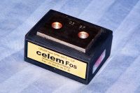
and what kind of driver to use ? i have idea to use zvs controller, so i can regulate power by changing frequency above resonance, and if i need more power, just get close to Fo.
zvs driver would be MC33067P
Linas, Tue Jan 24 2012, 05:49PM
if i want melt cobalt/iron material, and reach 2500^C, what kind of frequency and power should i use ?
i already have some heavy capacitor Celem 1uF 650A 550V capacitor and 60A ultra-fast IGBT for this project with some nice TC4422-TC4421 drivers.

and what kind of driver to use ? i have idea to use zvs controller, so i can regulate power by changing frequency above resonance, and if i need more power, just get close to Fo.
zvs driver would be MC33067P

Re: 4KW Induction Heater
Dr. ISOTOP, Tue Jan 24 2012, 08:39PM
Melting steel will require somewhere around 10KW and a nice crucible (I couldn't do it at 4KW {the limit of a 120V outlet}).
I would strongly recommend a half/full bridge with either a fixed-frequency TL494 driver or a PLL driver (or primary current feedback the way the DRSSTCs do it).
Dr. ISOTOP, Tue Jan 24 2012, 08:39PM
Linas wrote ...
if i want melt cobalt/iron material, and reach 2500^C, what kind of frequency and power should i use ?
i already have some heavy capacitor Celem 1uF 650A 550V capacitor and 60A ultra-fast IGBT for this project with some nice TC4422-TC4421 drivers.

and what kind of driver to use ? i have idea to use zvs controller, so i can regulate power by changing frequency above resonance, and if i need more power, just get close to Fo.
zvs driver would be MC33067P
if i want melt cobalt/iron material, and reach 2500^C, what kind of frequency and power should i use ?
i already have some heavy capacitor Celem 1uF 650A 550V capacitor and 60A ultra-fast IGBT for this project with some nice TC4422-TC4421 drivers.

and what kind of driver to use ? i have idea to use zvs controller, so i can regulate power by changing frequency above resonance, and if i need more power, just get close to Fo.
zvs driver would be MC33067P

Melting steel will require somewhere around 10KW and a nice crucible (I couldn't do it at 4KW {the limit of a 120V outlet}).
I would strongly recommend a half/full bridge with either a fixed-frequency TL494 driver or a PLL driver (or primary current feedback the way the DRSSTCs do it).
Re: 4KW Induction Heater
Tonskulus, Wed Feb 01 2012, 06:03PM
power requirement for melting steel, it all depends on amount of steel to be melted.
2kW is enough for quite small amounts when using good and sealed curcibles..
I used 1dl curcible and have been melting several different metals with it, using 2-3kW of input power.
Re: 4KW Induction Heater
Gabriel35, Fri Feb 17 2012, 01:14AM
Pretty Huge version!
I like It!
I got some new UPS transformers over here, and i think i'll start all the IH fun Again!
Just waiting for the right caps !
Gabriel35, Fri Feb 17 2012, 01:14AM
Pretty Huge version!
I like It!
I got some new UPS transformers over here, and i think i'll start all the IH fun Again!
Just waiting for the right caps !
Re: 4KW Induction Heater
tanc, Thu Nov 09 2017, 10:55AM
Hi everypeeps, firstly thanks for the wealth of info here, it has been a massive help as I too have built a parallel irfp260 'marco' IH. secondly truly amazing work from so many people.
reading through this thread i am particularly interested in the lm311/ne555/shunt protection circuit that marco talks of and how it can save 'countless mosfet' ( i am one the mosfet graveyard community). Can someone point me at a diagram that integrated this to marcos circuit?
my system is 10A variac, 140A ac arc welder, 100A rectifier, 4*irfp 260, 6.28uf and 5 turn 3.4uh which calculates to about 30khz.
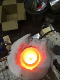
in an effort to avoid any more misfit deaths I am reluctant to turn everything up to 11 but at the same time my challenge is to melt glass in a graphite crucible.
last night it ran for 3 hours drawing 800w from the mains at 30vdc and 20-25 amps. this was enough to melt copper but not glass. in marcos film it looks like a steel bolt is bubbling which usually happens just prior to melting which would indicate 1200c?
so my question is what voltage and current should i be aiming for to achieve this temperature and what are the sensible maximums for these parameters to avoid fireworks?
any help in this direction would be very, very much appreciated


Re: 4KW Induction Heater
RogerInOhio, Thu Nov 09 2017, 03:14PM
It's hard to believe it's been almost 6 years since I started this thread. I have blown up plenty of MOSFETs with this heater but I have learned a few things that seem to have helped recently. The most common problem I would have is that at start up both MOSFETS would turn on at the same time. Making one of the gate bias resisters a little different value than the other (by about 10 percent) seems to help. Also I have been told that it's best to have the circuit turn on rapidly rather than have the voltage come up gradually on it.
Tanc, I have never tried to melt anything so I cant be much help there.
Re: 4KW Induction Heater
tanc, Fri Nov 17 2017, 08:59PM
Hi Roger,
Thank so much for the reply, it seems i am a few years behind most people on this!
I have i think by hapless luck and wholly persistence had a few days of success. I could not find any over current protection circuits that looked simple enough for me but whilst looking it occurred to me that if i can't have over current protection I can have under voltage protection. I had purchased some LM311 in anticipation of following Marcos advise and tried to arrange a voltage comparator that opens a relay that powers the varian. It runs off its own 24v psu and sure enough when the load gets too much the voltage drops and the varian turns off. Very simple. Not ideal I know but it has saved 10 mosfets since installation so it can stay for the time being.
I have doubled up on the IRFP260s and added large, thin copper sheet directly under them in the path of the forced air.
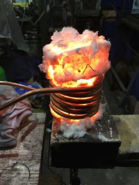
Today it has been running at 50v and 45a (>2kw) and have quite quickly melted iron. Sadly not hot enough to pour but definitely 1 homogenous lump in the bottom as opposed to the jar full of CI swarf the went in.
At the moment I have a 10A variac feeding a 140A ac arc welder which is about a 1:6 step down and with the load in I have to have the variac turned up full and the heater pulls the voltage down to about 45v-50v and draws 45A ac from the welder.
How can I double the power? (I need to generate 1600 deg celsius for the current task)
Also can you explain the coupling transformer that some design use in terms of what its for, where to put it in the circuit how to decide what it is made from and how many cores,turns,henries etc it needs to be?
here is a happy picture of todays success

Re: 4KW Induction Heater
RogerInOhio, Sat Nov 18 2017, 04:40PM
Hi Tanc, Im glad to see things are going well . Id'd say you are doing real good to be getting 2 KW out of your system. It seems to me that if you want significantly more power it would be best to go with a circuit that uses IGBTs. The IRFP260 is a low voltage beast so the impedance of your work coil is going to limit your output no mater how many you use.
I have been wanting to build a more powerful induction heater myself and what I might do is start with a DRSST and convert it into an induction heater. I know that sounds stupid but I'm not good at designing circuits and you can buy everything you need for a DRSST premade . Don't laugh, I'm the guy that just made a crappy Tesla coil by hooking up a primary coil with a secondary coil to a induction cooker circuit board that I bought off of eBay. You cant get an more lazy than that.
Re: 4KW Induction Heater
Sulaiman, Sat Nov 18 2017, 04:56PM
Whatever you heat in an induction heater, for a fixed heating power,
the maximum temperature is determined only by heat loss,
conduction and convection losses will dominate at lower temperatures with radiated heat loss setting the upper limit.

I would expect the rate of heat/energy absorbtion will drop off dramatically as iron passes its Curie Point (c770 C) and changes from ferromagnetic to paramagnetic.
Based on general principles, not induction heating experience - verify.
Sulaiman, Sat Nov 18 2017, 04:56PM
Whatever you heat in an induction heater, for a fixed heating power,
the maximum temperature is determined only by heat loss,
conduction and convection losses will dominate at lower temperatures with radiated heat loss setting the upper limit.

I would expect the rate of heat/energy absorbtion will drop off dramatically as iron passes its Curie Point (c770 C) and changes from ferromagnetic to paramagnetic.
Based on general principles, not induction heating experience - verify.
Re: 4KW Induction Heater
tanc, Wed Nov 22 2017, 10:08AM
Hi Roger, Thanks again for the quick reply. Its a shame to read what you wrote about the IRFP 260 as i have just replenished my stock and now feel that I know the circuit quite well. Also I have been reading this post from top to bottom several times and had decided to follow your project to try for 4 kw. Your video seems to heat that pipe extremely quickly and I can't help but think if there was an insulated crucible in the coil that ir would be able to pour iron with ease. do you still have the schematics and if so would send me a copy?
Re: 4KW Induction Heater
RogerInOhio, Wed Nov 29 2017, 02:24PM
Hi Tanc, in my induction heater uses two sets of four mosfets. The sources and drains are connected directly in parallel but each gate has it's own biasing resistor and zener diode. If I could insulate the work piece well enough maybe I could get it to melt but like Sulaiman said once the temperature gets to a certain point the hysteresis losses in the iron decrease so the load starts to drop off.
Re: 4KW Induction Heater
tanc, Thu Dec 07 2017, 08:38PM
HI Sulaiman,
Thanks for the input. Are you saying that if the insulation is good enough then even a 500w heater will melt iron? During my experiments i have suspected this to be the case. Any workpiece gets hot, glows red and sometimes orange and even yellow once or twice but it is only when the work is wrapped in ceramic fibre that things start to get interesting.
I am considering building a box for the work coil that will fully encase it in a mixture of pearlite and fire cement in an effort to reduce loss.
Last night I melted down the copper from some dead mossiest and cast some 'FET' blocks that clamp around the straight section of the work coil tubing and accept 4 mossiest each. hey ho
Re: 4KW Induction Heater
tanc, Tue Dec 12 2017, 02:36PM
HI Sulaiman,
Thanks for the input. Are you saying that if the insulation is good enough then even a 500w heater will melt iron? During my experiments i have suspected this to be the case. Any workpiece gets hot, glows red and sometimes orange and even yellow once or twice but it is only when the work is wrapped in ceramic fibre that things start to get interesting.
I am considering building a box for the work coil that will fully encase it in a mixture of pearlite and fire cement in an effort to reduce loss.
Last night I melted down the copper from some dead mossiest and cast some 'FET' blocks that clamp around the straight section of the work coil tubing and accept 4 mossiest each. hey ho
Re: 4KW Induction Heater
colin heath, Sun Jul 29 2018, 11:49AM
Hi Roger,
Wow it's been some time since I logged in and now starting to play with induction heaters again. I did exactly as you mention and used Steve Wards DRSSTC driver board with manual frequency input instead of feedback from tesla coil primary.
I ran it at 20kHz (which killed my sky dish LNB because of no filters to mains).
I did the reverse of everybody else and went high voltage, low capacitance. Mine had around 100 turns of 2.5mm insulated wire wrapped around some insulated bricks and a teal coil sized tank cap.
I used a steel crucible to melt aluminium and it was much faster than my standard electric furnace.
I will see if I can dig out my old details and threads. I had to keep frequency above or below resonant as I didn't have the over current circuit running. At resonant it pulled huge power (as it would).
Hope this helps a little and I will have a dig around.
RogerInOhio wrote ...
Hi Tanc, Im glad to see things are going well . Id'd say you are doing real good to be getting 2 KW out of your system. It seems to me that if you want significantly more power it would be best to go with a circuit that uses IGBTs. The IRFP260 is a low voltage beast so the impedance of your work coil is going to limit your output no mater how many you use.
I have been wanting to build a more powerful induction heater myself and what I might do is start with a DRSST and convert it into an induction heater. I know that sounds stupid but I'm not good at designing circuits and you can buy everything you need for a DRSST premade . Don't laugh, I'm the guy that just made a crappy Tesla coil by hooking up a primary coil with a secondary coil to a induction cooker circuit board that I bought off of eBay. You cant get an more lazy than that.
Print this page