 noise for buck/boost converter noise for buck/boost converter
|
|
|
IamSmooth
|
|
Mon Nov 15 2010, 04:35AM
|

|
|
 Registered Member #190
Joined: Fri Feb 17 2006, 12:00AM
Location:
Posts: 1567
|
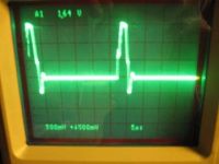
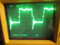
I am still troubleshooting my initial run at building a buck or buck/boost converter. My driver is a tl494 which sends its pwm to a FOD3180. There is a 0.1uf bypass capacitor on this chip. The output of the 3180 on pins 6&7 goes through a 10R resistor and a ferrite bead to an IGBT. I have a 15v zener for to limit the positive side and a 6.2v zener to limit the negative side of the gate drive. The lead length on the board is about 3" to the gate. I should shorten it. What I get is an oscillation when the gate signal goes to zero. The oscillations are more pronounced when I increase the collector to emitter voltage and the duty. There is no FWD across the Collector-emitter.
here are the images. The scale is 5v/division. The switching frequency is about 36khz. I am worried that this is causing spurious turn-ons. What can I do to fix this?
Also, would a surface mount ferrite bead like this one

reduce my switching spikes on the output and be sufficient for 50A output? I see it has an 8A rating, but I did not know if this is for the current of the filtered oscillations, and not the DC component.


|
|
Back to top
|
|
|
Daedronus
|
|
 Registered Member #2329
Joined: Tue Sept 01 2009, 08:25AM
Location:
Posts: 370
|
When you measure the gate waveform make sure the probe is attached directly to the gate pin and the ground clip of the probe is attached directly to the emitter pin of the igbt.
I would also take out the ferrite bead.
edit: the point is that if your ground clip is far from the igbt's gate pin your reading will be screwed up because of the ground loops.
|
|
Back to top
|
|
Moderator(s): Chris Russell, Noelle, Alex, Tesladownunder, Dave Marshall, Dave Billington, Bjørn, Steve Conner, Wolfram, Kizmo, Mads Barnkob
|
|
Powered by e107 Forum System
|

