If you need assistance, please send an email to forum at 4hv dot org. To ensure your email is not marked as spam, please include the phrase "4hv help" in the subject line. You can also find assistance via IRC, at irc.shadowworld.net, room #hvcomm.
Support 4hv.org!
Donate:
4hv.org is hosted on a dedicated server. Unfortunately, this server costs and we rely on the help of site members to keep 4hv.org running. Please consider donating. We will place your name on the thanks list and you'll be helping to keep 4hv.org alive and free for everyone. Members whose names appear in red bold have donated recently. Green bold denotes those who have recently donated to keep the server carbon neutral.
Special Thanks To:
Aaron Holmes
Aaron Wheeler
Adam Horden
Alan Scrimgeour
Andre
Andrew Haynes
Anonymous000
asabase
Austin Weil
barney
Barry
Bert Hickman
Bill Kukowski
Blitzorn
Brandon Paradelas
Bruce Bowling
BubeeMike
Byong Park
Cesiumsponge
Chris F.
Chris Hooper
Corey Worthington
Derek Woodroffe
Dalus
Dan Strother
Daniel Davis
Daniel Uhrenholt
datasheetarchive
Dave Billington
Dave Marshall
David F.
Dennis Rogers
drelectrix
Dr. John Gudenas
Dr. Spark
E.TexasTesla
eastvoltresearch
Eirik Taylor
Erik Dyakov
Erlend^SE
Finn Hammer
Firebug24k
GalliumMan
Gary Peterson
George Slade
GhostNull
Gordon Mcknight
Graham Armitage
Grant
GreySoul
Henry H
IamSmooth
In memory of Leo Powning
Jacob Cash
James Howells
James Pawson
Jeff Greenfield
Jeff Thomas
Jesse Frost
Jim Mitchell
jlr134
Joe Mastroianni
John Forcina
John Oberg
John Willcutt
Jon Newcomb
klugesmith
Leslie Wright
Lutz Hoffman
Mads Barnkob
Martin King
Mats Karlsson
Matt Gibson
Matthew Guidry
mbd
Michael D'Angelo
Mikkel
mileswaldron
mister_rf
Neil Foster
Nick de Smith
Nick Soroka
nicklenorp
Nik
Norman Stanley
Patrick Coleman
Paul Brodie
Paul Jordan
Paul Montgomery
Ped
Peter Krogen
Peter Terren
PhilGood
Richard Feldman
Robert Bush
Royce Bailey
Scott Fusare
Scott Newman
smiffy
Stella
Steven Busic
Steve Conner
Steve Jones
Steve Ward
Sulaiman
Thomas Coyle
Thomas A. Wallace
Thomas W
Timo
Torch
Ulf Jonsson
vasil
Vaxian
vladi mazzilli
wastehl
Weston
William Kim
William N.
William Stehl
Wesley Venis
The aforementioned have contributed financially to the continuing triumph of 4hv.org. They are deserving of my most heartfelt thanks.
Registered Member #51
Joined: Thu Feb 09 2006, 04:17AM
Location:
Posts: 263
I am in the process of building a small class e SSTC. These audio modulated coils seem to be very popular these days so I thought Id have a try at building one. I am interested to hear how everyone provides the drive voltage for the primary coil. I was planning on rectifying the mains and using that as my high voltage power supply, the only problem is that i have no GDT for my mosfet, it is directly fed from an IXDD414, so the power section of the circuit shares a common ground with the control section. It seems to me that I need some isolation somewhere. I could let the "ground" of the control and power section float with mains voltage, but then id have to isolate everything else (audio in, etc).
Id love to see if anyone has any tips for designing a GDT so that I can isolate my control and power sections. Ive tried with a few ferrite cores, but I only seem to get ringing and noise out, and not the square/sine wave that I need. My circuit is similar to Steve Wards driver, im using a hex inverter before the IXDD414, then a 10ohm resistor to my mosfets gate for now.
My coil resonates at between 4mhz and 3.7mhz. Im currently not doing class e seeing as I dont have a tank cap connected to the circuit. The coil works well tho from 24v input and will light a fluorescent bulb very nicely.
Registered Member #63
Joined: Thu Feb 09 2006, 06:18AM
Location:
Posts: 1425
Sir, you may reconsider your design; it's fine as-is and can be done without a GDT, but isn't recommended for off-line work.
Think of your primary series circuit like this: Vcc >> primary >> drain >> source >> gnd.
Nothing needs to be floating. Turn MOSFET on, current flows through primary. Turn MOSFET off, and you have a mess across drain-source that's up to you to try to control with capacitors etc as you see fit.
Otherwise, if you wish to have isolation, you will need a gate driver transformer that looks like THIS: or THIS:
but NOT like this:
Similarly, you will need a PCB with groundplane and coplanar traces that looks like THIS:
Registered Member #51
Joined: Thu Feb 09 2006, 04:17AM
Location:
Posts: 263
Here is a diagram of the concern that I have. I probably should have posted this first buy hopefully it will help. I think my problem is isolation between mains ground and neutral.
Registered Member #63
Joined: Thu Feb 09 2006, 06:18AM
Location:
Posts: 1425
Connect your 0V to ground. Huzzah, now they're at the same potential.
I wouldn't recommend this kind of feedback for your coil; if the MOSFET stays on for any reason (such as startup), it's toast. Try plugging a signal generator into the inverters, reduce the gate resistor to 1R or remove it altogether, and play around at initially low voltages to see what response you get with different shunt capacitances.
Registered Member #51
Joined: Thu Feb 09 2006, 04:17AM
Location:
Posts: 263
Thanks for the quick reply, I simply wasn't sure if i could just connect 0v marked in the circuit to the "safe to touch" mains ground and still have that ground safe to touch.
Good point about the mosfet getting stuck on, I may consider some protection circuit or maybe even just a fuse. Im currently playing with just 24vdc in, so nothing too bad should happen.
Registered Member #1232
Joined: Wed Jan 16 2008, 10:53PM
Location: Doon tha Toon!
Posts: 881
You can't connect the 0v side of the mains rectifier to mains ground without getting a big bang and a blown rectifier. You need to use a mains isolation transformer, then you can ground the 0v line and scope the MOSFET waveforms safely.
If it was me, I would choose a transformer that will drop the voltage slightly too. 170VDC is quite high for a Class E amplifier - With 170VDC supply the drain voltage will repeatedly hit 600v and could try to go higher during the tuning process if things aren't set up properly. Even an 800V MOSFET doesn't give much headroom.
I wouldn't recommend using a high-frequency RF isolation transformer to just isolate the gate-drive. It still doesn't fix the problem of not being able to safely scope the MOSFET drain waveform which is vital to setting up a Class E amplifier.
Registered Member #51
Joined: Thu Feb 09 2006, 04:17AM
Location:
Posts: 263
Thanks for the advice. I will use two matching transformers in testing when i need isolation. I would like to learn how to properly build an RF transformer tho, in case I want to isolate the mosfet power section from the control electronics in the final design.
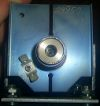
I tested a transformer that I made with a .75" toroidal core from what I assume was an EMI noise reducer. I used 5 turns of 18awg coax, and the transformer seems to work from about 1mhz on up to 5mhz, which is the limit of my home made signal generator.
I have some questions regarding the drive and output of my RF transformer. I would really love to learn more about this high frequency stuff, but sadly, I'm still in highschool and lack the college level knowledge of many members.
In the above circuit I posted, if i connect one winding of my GDT to the output of my IXDD414 and ground, and i feed my inverter section with a signal generator, will the other winding produce a true AC voltage? I assume it will, but I'm not sure because the primary winding will only be seeing pulsed current in one direction.
I ask this because I'm not sure if i can ground one end of the secondary winding and connect the other to the gate, or if i need to set a bias voltage on the gate of the mosfet to get it to fully switch.
Hopefully the attached image will fully explain my concern. Thanks for any help.
Registered Member #63
Joined: Thu Feb 09 2006, 06:18AM
Location:
Posts: 1425
I had mistakenly assumed you were using a step-down transformer.
Don't forget to put a capacitor in series with your primary winding. The secondary will swing "-6V to +6V", so you'll need to use a stepup ratio in the windings, or rely on secondary resonance to get that voltage higher.
Registered Member #51
Joined: Thu Feb 09 2006, 04:17AM
Location:
Posts: 263
I ended up designing the circuit below. It was hard to correctly design the GDT, but this one seems to work at 5mhz - 1mhz. I decided to bias the gate of the mosfet so that it could be switched with only a 6v positive swing. Ill set the bias voltage to 3v above source so that the 6v swing gets the gate above the 6v plateau rating of this fet. Using my signal generator into the antenna connection on the board, I get a sine like wave on the gate of the transistor at 4mhz. with the bias set correctly, the mosfet should see between -3v and +9v on its gate terminal.
If this thing can actually produce some sparks, I may post my design and more pictures on the projects board.
This site is powered by e107, which is released under the GNU GPL License. All work on this site, except where otherwise noted, is licensed under a Creative Commons Attribution-ShareAlike 2.5 License. By submitting any information to this site, you agree that anything submitted will be so licensed. Please read our Disclaimer and Policies page for information on your rights and responsibilities regarding this site.


 4mhz GDT?