
High voltage probe for O-scope, 1 of 2, ( DEVELOPMENT ).
Patrick, Fri Feb 04 2011, 04:56AM[Gen 4, Type 3, Mod 40, Rev H, Ver 2.0, Attempt 9] for HV O-scope Probes.
Ive been reading this...
]us5107201hvprobe.pdf[/file]

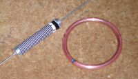
14awg wire copper. 75M ohm, 20kV, 3.4W resistor with the main resistive material cut.
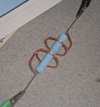
I presume the curve will decrease field intensity better then the angled one.
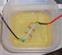
2.0pF in air, 4.0pF in olive oil. I had to destroy this resistor to make the capacity measurement, I ground through the Ruthenium-oxide resistive element. before with a good resistor my C meter said 0.8pF - 0.0pF (@ 2Vrms into 75M ohms!) after cutting it, it read a stable 4.0-4.2 pF in oil.
Re: High voltage probe for O-scope, 1 of 2, ( DEVELOPMENT ).
Pinky's Brain, Fri Feb 04 2011, 02:06PM
If you make a divider as tall and for as much voltage as the North Star VD probes you will be left with << 1 pF ... whereas North Star has ~20 pF, and that capacitance isn't there for naught.
This seems only enough for a handheld probe with one or 2 resistors.
Re: High voltage probe for O-scope, 1 of 2, ( DEVELOPMENT ).
Proud Mary, Fri Feb 04 2011, 02:38PM
It suggests a skeletonic version of the individual resistor shielding arrangements in the Park Resistor standard.
Proud Mary, Fri Feb 04 2011, 02:38PM
It suggests a skeletonic version of the individual resistor shielding arrangements in the Park Resistor standard.
Re: High voltage probe for O-scope, 1 of 2, ( DEVELOPMENT ).
Patrick, Fri Feb 04 2011, 03:34PM
Park resistor thread
Park resistor PDF
Patrick, Fri Feb 04 2011, 03:34PM
Pinky's Brain wrote ...
If you make a divider as tall and for as much voltage as the North Star VD probes you will be left with << 1 pF ... whereas North Star has ~20 pF, and that capacitance isn't there for naught.
This seems only enough for a handheld probe with one or 2 resistors.
Two in series was my target. I was warned that too much capacity would limit bandwidth or rise time.If you make a divider as tall and for as much voltage as the North Star VD probes you will be left with << 1 pF ... whereas North Star has ~20 pF, and that capacitance isn't there for naught.
This seems only enough for a handheld probe with one or 2 resistors.
Proud Mary wrote ...
It suggests a skeletonic version of the individual resistor shielding arrangements in the Park Resistor standard.
I technically wasnt shielding the resistor with the cap, have'nt got that far yet.It suggests a skeletonic version of the individual resistor shielding arrangements in the Park Resistor standard.
Park resistor thread

Park resistor PDF

Re: High voltage probe for O-scope, 1 of 2, ( DEVELOPMENT ).
Patrick, Mon Feb 07 2011, 05:48AM
I believe the Tek P6013, P6014, P6015 all have that metal shield so they can treat the whole path as a lossy-transmission line?
Im aiming for these:
300M for 24kV, 2 Probes
600M for 45kV, 3 Probes (0ne of these will be a +-1% calibration standard)
800M for 60kV, 2 Probes
1.40G for 100kV, 1 probe
What about this...
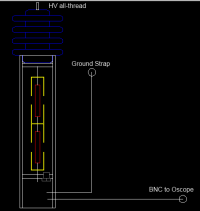
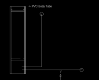
Yellow are copper "Park-like" Caps, Red are resistors. The bottom most section are where compensation and LV componets live. ( Approx. 14" tall )
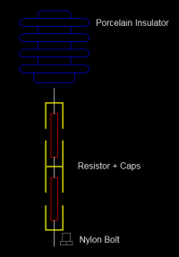
Patrick, Mon Feb 07 2011, 05:48AM
Pinky's Brain wrote ...
To me it seems that a handheld probe is significantly harder to design than a standalone probe connected through a low induction copper strap. With a stand alone probe you can keep the electric field across the HV resistor uniform (like your capacitive hoops in the other thread) which simplifies modelling it's operation.
The moment you put a grounded metal shield around it which goes close to the tip the behaviour of the system becomes much harder to predict.
The NorthStar's do have a large topand bottom ring, to equalize the field and as you said I guess thats where some capacity comes from too.To me it seems that a handheld probe is significantly harder to design than a standalone probe connected through a low induction copper strap. With a stand alone probe you can keep the electric field across the HV resistor uniform (like your capacitive hoops in the other thread) which simplifies modelling it's operation.
The moment you put a grounded metal shield around it which goes close to the tip the behaviour of the system becomes much harder to predict.
I believe the Tek P6013, P6014, P6015 all have that metal shield so they can treat the whole path as a lossy-transmission line?
Im aiming for these:
300M for 24kV, 2 Probes
600M for 45kV, 3 Probes (0ne of these will be a +-1% calibration standard)
800M for 60kV, 2 Probes
1.40G for 100kV, 1 probe
What about this...

Yellow are copper "Park-like" Caps, Red are resistors. The bottom most section are where compensation and LV componets live. ( Approx. 14" tall )


Re: High voltage probe for O-scope, 1 of 2, ( DEVELOPMENT ).
Patrick, Wed Feb 09 2011, 02:20AM
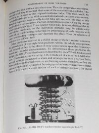
Exceprts from "High Voltage Engineering Fundamentals" E. Kuffel, W.S. Zaengl. Pergamon Press.
isbn: 0-08-024213-8
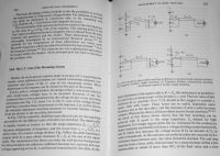
4 main types of dividers.
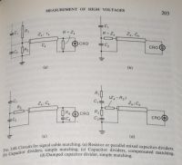
Type (a) is my most favored design, though there is a thread i started which shows another like type (d).
Damped resistor type, as seen in fig (d).(actually this is a composite of (a) and (d).)


look at page 2 !
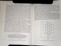
The "Park" idea yet again
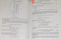
capacitence distributed
across the length of the resistor.
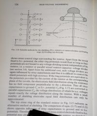
field gradient.
Patrick, Wed Feb 09 2011, 02:20AM
Exceprts from "High Voltage Engineering Fundamentals" E. Kuffel, W.S. Zaengl. Pergamon Press.
isbn: 0-08-024213-8

4 main types of dividers.

Type (a) is my most favored design, though there is a thread i started which shows another like type (d).

Damped resistor type, as seen in fig (d).(actually this is a composite of (a) and (d).)


look at page 2 !

The "Park" idea yet again

capacitence distributed
across the length of the resistor.

field gradient.

Re: High voltage probe for O-scope, 1 of 2, ( DEVELOPMENT ).
Patrick, Thu Feb 10 2011, 01:57AM
Construction of the next prototype will now commence
related thread:
Patrick, Thu Feb 10 2011, 01:57AM
Construction of the next prototype will now commence
related thread:

Re: High voltage probe for O-scope, 1 of 2, ( DEVELOPMENT ).
Patrick, Tue Feb 22 2011, 07:24PM
Updates and Pics.
Ive had real problems with the caps here, please comment. ive had series capacitence be larger than the parallel cap ? what, how is that possible?! And, ive had each cap very from 1.1 pF to 3.3pF, now i think there stable at 2.3 to 2.8 pF each. I think there both actually close to 2.5 pF, and the dimensions are withins thousandths in any dimension, so i dont see how it can vary unless its other objects on the table that bias them. Also, the tubes have the same half circle radius as the pipe wall thickness (0.040")
Please comment and advise me if im totally wrong, or if you have a better set up for measuring pF's in the single digit range.

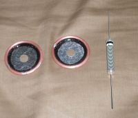
Basic Components, tubes for caps, and two 200Mohm resistors.

resistors were ground through till open circuit, so as to not effect the Picofarad measurements.

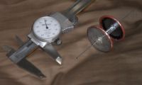
Assembly and scale.
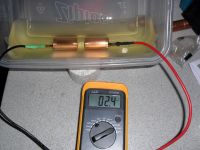
Olive oil, 2.4 pF, and cap check at 0.570" gap. (copper spool support)
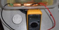
Left cap at 2.8 pF, 0.570" gap. (copper spool support)
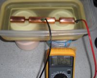
Right cap at 2.5 pF, 0.570" gap. (kool-aid support)
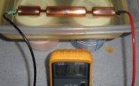
Series cap is 1.1pF. (kool-aid support)
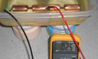
Left cap at 2.5 pF, 0.570" gap. (kool-aid support)

Plan view, top.

Isometric view, side.
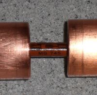
Caddock.
Patrick, Tue Feb 22 2011, 07:24PM
Updates and Pics.
Ive had real problems with the caps here, please comment. ive had series capacitence be larger than the parallel cap ? what, how is that possible?! And, ive had each cap very from 1.1 pF to 3.3pF, now i think there stable at 2.3 to 2.8 pF each. I think there both actually close to 2.5 pF, and the dimensions are withins thousandths in any dimension, so i dont see how it can vary unless its other objects on the table that bias them. Also, the tubes have the same half circle radius as the pipe wall thickness (0.040")
Please comment and advise me if im totally wrong, or if you have a better set up for measuring pF's in the single digit range.

Basic Components, tubes for caps, and two 200Mohm resistors.

resistors were ground through till open circuit, so as to not effect the Picofarad measurements.

Assembly and scale.

Olive oil, 2.4 pF, and cap check at 0.570" gap. (copper spool support)

Left cap at 2.8 pF, 0.570" gap. (copper spool support)

Right cap at 2.5 pF, 0.570" gap. (kool-aid support)

Series cap is 1.1pF. (kool-aid support)

Left cap at 2.5 pF, 0.570" gap. (kool-aid support)
Plan view, top.

Isometric view, side.

Caddock.
Re: High voltage probe for O-scope, 1 of 2, ( DEVELOPMENT ).
Proud Mary, Tue Feb 22 2011, 08:08PM
Have you measured the capacitance between the two meter leads on their own - terminated in the oil bath with nothing attached to their ends? You have to account for, or null out, stray capacitance somehow.
Proud Mary, Tue Feb 22 2011, 08:08PM
Have you measured the capacitance between the two meter leads on their own - terminated in the oil bath with nothing attached to their ends? You have to account for, or null out, stray capacitance somehow.
Re: High voltage probe for O-scope, 1 of 2, ( DEVELOPMENT ).
Patrick, Tue Feb 22 2011, 08:12PM
I think pF measurements are just prone to alot of crap?
Also, proud mary this is my interpretation of the "park" concept.
Patrick, Tue Feb 22 2011, 08:12PM
Proud Mary wrote ...
Have you measured the capacitance between the two meter leads on their own - terminated in the oil bath with nothing attached to their ends? You have to account for, or null out, stray capacitance somehow.
yes, nulling was the first thing I did, multiple times throughout the day/experiment. And got multiple consistent results, so I belive the meter. (i even was careful with how close and the shape of those two wires)Have you measured the capacitance between the two meter leads on their own - terminated in the oil bath with nothing attached to their ends? You have to account for, or null out, stray capacitance somehow.
I think pF measurements are just prone to alot of crap?
Also, proud mary this is my interpretation of the "park" concept.
Re: High voltage probe for O-scope, 1 of 2, ( DEVELOPMENT ).
Proud Mary, Tue Feb 22 2011, 08:48PM
When you're dealing with just a few picofarads, I should think that stray capacitance can stick its snout in from all sorts of directions. Measurement of very low capacitance isn't something I know much about, I'm afraid, Patrick.
Proud Mary, Tue Feb 22 2011, 08:48PM
When you're dealing with just a few picofarads, I should think that stray capacitance can stick its snout in from all sorts of directions. Measurement of very low capacitance isn't something I know much about, I'm afraid, Patrick.
Re: High voltage probe for O-scope, 1 of 2, ( DEVELOPMENT ).
Patrick, Tue Feb 22 2011, 08:53PM
Shit. How did park describe the significance of the resistor end plate? im look through my book but i dont see anything usefull yet.
I may just add flanges to increase the capacity to 5 pF or some more stable value.
Patrick, Tue Feb 22 2011, 08:53PM
Shit. How did park describe the significance of the resistor end plate? im look through my book but i dont see anything usefull yet.
I may just add flanges to increase the capacity to 5 pF or some more stable value.
Re: High voltage probe for O-scope, 1 of 2, ( DEVELOPMENT ).
Proud Mary, Wed Feb 23 2011, 12:34AM
Have you got any high quality close tolerance low pF capacitors to use as standards?
Proud Mary, Wed Feb 23 2011, 12:34AM
Patrick wrote ...
Shit. How did park describe the significance of the resistor end plate? im look through my book but i dont see anything usefull yet.
I may just add flanges to increase the capacity to 5 pF or some more stable value.
Shit. How did park describe the significance of the resistor end plate? im look through my book but i dont see anything usefull yet.
I may just add flanges to increase the capacity to 5 pF or some more stable value.
Have you got any high quality close tolerance low pF capacitors to use as standards?
Re: High voltage probe for O-scope, 1 of 2, ( DEVELOPMENT ).
Patrick, Wed Feb 23 2011, 01:26AM
OOoooooo! the ones you gave me... 2.7 - 72.5 pF vari cap!!! what is it i should do?
and a 50 pF ( +- 1 pF ) that reads to 50.3 pF.
Patrick, Wed Feb 23 2011, 01:26AM
OOoooooo! the ones you gave me... 2.7 - 72.5 pF vari cap!!! what is it i should do?
and a 50 pF ( +- 1 pF ) that reads to 50.3 pF.
Re: High voltage probe for O-scope, 1 of 2, ( DEVELOPMENT ).
Proud Mary, Wed Feb 23 2011, 10:19AM
I've just had a rummage in a box of low pF silver micas for you, and see that below 10pF the percentage tolerance system gives way to accuracy expressed directly in pF e.g. 4.7pF ±0.5pF.
Where a very precise low pF capacitor is required - say in RF tuning - the usual approach is make C larger than needed, and to put Ctrim in series with it to bracket the desired range, or make C smaller than the desired capacitance, and put Ctrim in parallel with it.
Re: High voltage probe for O-scope, 1 of 2, ( DEVELOPMENT ).
Steve Conner, Wed Feb 23 2011, 11:06AM
I think the best way to test a probe like this is fire it up and look at the response to a square wave input. You're testing the capacitance in exactly the way you intend to use it. If you can get a nice square wave, ship it.
Because of linearity, the response will be the same for all voltages, so you don't need a 10,000 volt square wave to test it. Just the smallest that your scope can resolve. Maybe 100V or even 10V would do. Most DSOs have an averaging feature that you can use to help resolve a smaller signal.
Re: High voltage probe for O-scope, 1 of 2, ( DEVELOPMENT ).
Patrick, Thu Feb 24 2011, 08:51AM
I may not be able to generate a 100 v squarewave real well. should i compare a known good probe to my HV probe whi;e looking at the same square input?
Patrick, Thu Feb 24 2011, 08:51AM
Steve McConner wrote ...
I think the best way to test a probe like this is fire it up and look at the response to a square wave input. You're testing the capacitance in exactly the way you intend to use it. If you can get a nice square wave, ship it.
Because of linearity, the response will be the same for all voltages, so you don't need a 10,000 volt square wave to test it. Just the smallest that your scope can resolve. Maybe 100V or even 10V would do. Most DSOs have an averaging feature that you can use to help resolve a smaller signal.
does the capacitence effect the rates of change or the whole wave? can you draw waveforms of ideal and then of annomoulus conditions? I think the best way to test a probe like this is fire it up and look at the response to a square wave input. You're testing the capacitance in exactly the way you intend to use it. If you can get a nice square wave, ship it.
Because of linearity, the response will be the same for all voltages, so you don't need a 10,000 volt square wave to test it. Just the smallest that your scope can resolve. Maybe 100V or even 10V would do. Most DSOs have an averaging feature that you can use to help resolve a smaller signal.
I may not be able to generate a 100 v squarewave real well. should i compare a known good probe to my HV probe whi;e looking at the same square input?
Re: High voltage probe for O-scope, 1 of 2, ( DEVELOPMENT ).
Steve Conner, Thu Feb 24 2011, 11:43AM
If the probe is "just right" the waveform will be a perfect square wave.
If it's not, it will be some bizarre shape. The simplest case is that the leading edge either overshoots or undershoots.

If the shields in your HV assembly have the wrong capacitance, to a first-order approximation, it has the same effect as a regular scope probe's compensation trimmer being set wrong. Turning that logic on its head, there isn't just one right capacitance for the HV shields: rather a range that you can compensate by twiddling a trimmer in the compensation box you'll have to build.
You should do this so you can have a look at all the other time constants in there that you'll need to compensate eventually.
Steve Conner, Thu Feb 24 2011, 11:43AM
If the probe is "just right" the waveform will be a perfect square wave.
If it's not, it will be some bizarre shape. The simplest case is that the leading edge either overshoots or undershoots.

If the shields in your HV assembly have the wrong capacitance, to a first-order approximation, it has the same effect as a regular scope probe's compensation trimmer being set wrong. Turning that logic on its head, there isn't just one right capacitance for the HV shields: rather a range that you can compensate by twiddling a trimmer in the compensation box you'll have to build.
You should do this so you can have a look at all the other time constants in there that you'll need to compensate eventually.
Re: High voltage probe for O-scope, 1 of 2, ( DEVELOPMENT ).
Patrick, Thu Feb 24 2011, 08:12PM
Patrick, Thu Feb 24 2011, 08:12PM
Steve McConner wrote ...
If the shields in your HV assembly have the wrong capacitance, to a first-order approximation, it has the same effect as a regular scope probe's compensation trimmer being set wrong. Turning that logic on its head, there isn't just one right capacitance for the HV shields: rather a range that you can compensate by twiddling a trimmer in the compensation box you'll have to build.
You should do this so you can have a look at all the other time constants in there that you'll need to compensate eventually.
Ok ill post waveforms here when I get them for evaluation, these tests and builds are expensive and difficult so being wrong is no light issue.If the shields in your HV assembly have the wrong capacitance, to a first-order approximation, it has the same effect as a regular scope probe's compensation trimmer being set wrong. Turning that logic on its head, there isn't just one right capacitance for the HV shields: rather a range that you can compensate by twiddling a trimmer in the compensation box you'll have to build.
You should do this so you can have a look at all the other time constants in there that you'll need to compensate eventually.
Re: High voltage probe for O-scope, 1 of 2, ( DEVELOPMENT ).
Patrick, Fri Feb 25 2011, 11:59PM
I have solved the capacitence problem, it was due to complex fringing field flux wandering so badly. My physics book held the answer.
Capacictors are most predictable with wide plates at narrow distances, thus the calculus of the large uniform field overwhelms the little non-uniform (fringe) flux at the edges of thin plates. This was the problem, two thin wall pipes acting with only 0.040" plate breadth, with 2.4 inches of circumference across a gap of 0.570". The 0.040" dimension was too insignificant compared to the 2.4", and 0.570" so the field was unstable and difficult to control, varied wildly from 1pf to 4pf quickly when all demensions were held constant.
I will post pictures to describe the problem and then the solution soon.
Re: High voltage probe for O-scope, 1 of 2, ( DEVELOPMENT ).
Patrick, Mon Feb 28 2011, 07:23PM
EDIT: (UPDATE: 15.4pF + 15.4pF = 7.0pF !!! (seriesed) Capacitience Problem SOLVED! And thier rock stable too.
I belive the 7.7pF vs 7.0pF discrepency is due to the leads' capacitence and nulling. I think its fine as long as the two inpdependent capacitences are close/exactly the same. I have class now, will be back to harmonize the math later.) All of this was later proved wrong, the capacitences do not divide evenly, due to "Molar-Coulomb charging" on dissimilar surface areas. The steel tube at a half length has twice the SA of the full copper tube.

The tube with insulating fins.

FR4 composite fins, nevermind the scorched carbon. Ths is a non-fucnctional mock-up.
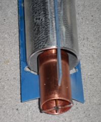
One end cap, with copper and steel plates.
Patrick, Mon Feb 28 2011, 07:23PM
EDIT: (UPDATE: 15.4pF + 15.4pF = 7.0pF !!! (seriesed) Capacitience Problem SOLVED! And thier rock stable too.
I belive the 7.7pF vs 7.0pF discrepency is due to the leads' capacitence and nulling. I think its fine as long as the two inpdependent capacitences are close/exactly the same. I have class now, will be back to harmonize the math later.) All of this was later proved wrong, the capacitences do not divide evenly, due to "Molar-Coulomb charging" on dissimilar surface areas. The steel tube at a half length has twice the SA of the full copper tube.

The tube with insulating fins.

FR4 composite fins, nevermind the scorched carbon. Ths is a non-fucnctional mock-up.

One end cap, with copper and steel plates.
Re: High voltage probe for O-scope, 1 of 2, ( DEVELOPMENT ).
Proud Mary, Tue Mar 01 2011, 01:12AM
Great too see it all going swimmingly, Patrick!
Proud Mary, Tue Mar 01 2011, 01:12AM
Great too see it all going swimmingly, Patrick!

Re: High voltage probe for O-scope, 1 of 2, ( DEVELOPMENT ).
Patrick, Tue Mar 01 2011, 04:08AM
Patrick, Tue Mar 01 2011, 04:08AM
Proud Mary wrote ...
Great too see it all going swimmingly, Patrick!
No! I managed to find a new crisis to play with. Their sharing 1.1pF's THROUGH the tube! Damt it thats why the should be 7.7pF is actually 7.0pF, dam it, dam it, dam it. Great too see it all going swimmingly, Patrick!

Re: High voltage probe for O-scope, 1 of 2, ( DEVELOPMENT ).
Proud Mary, Tue Mar 01 2011, 11:08AM
It's always reassuring to meet fellow OSFTSB Club members.
(One Step Forward, Two Steps Back)
Club motto: In this disaster, business is always round the corner
It's life, Patrick, but not as we know it!
Proud Mary, Tue Mar 01 2011, 11:08AM
Patrick wrote ...
Proud Mary wrote ...
Great too see it all going swimmingly, Patrick!
No! I managed to find a new crisis to play with. Their sharing 1.1pF's THROUGH the tube! Damt it thats why the should be 7.7pF is actually 7.0pF, dam it, dam it, dam it. Great too see it all going swimmingly, Patrick!

It's always reassuring to meet fellow OSFTSB Club members.
(One Step Forward, Two Steps Back)
Club motto: In this disaster, business is always round the corner
It's life, Patrick, but not as we know it!

Re: High voltage probe for O-scope, 1 of 2, ( DEVELOPMENT ).
Patrick, Tue Mar 01 2011, 05:37PM

Patrick, Tue Mar 01 2011, 05:37PM
Proud Mary wrote ...
It's always reassuring to meet fellow OSFTSB Club members.
(One Step Forward, Two Steps Back)
Club motto: In this disaster, business is always round the corner
It's life, Patrick, but not as we know it!
LOL! Yes that says it all ! It's always reassuring to meet fellow OSFTSB Club members.
(One Step Forward, Two Steps Back)
Club motto: In this disaster, business is always round the corner
It's life, Patrick, but not as we know it!


Re: High voltage probe for O-scope, 1 of 2, ( DEVELOPMENT ).
Patrick, Thu Mar 24 2011, 05:55AM
[Gen 4, Type 3, Mod 40, Rev H, Ver 2.0, Attempt 9] for HV O-scope Probes, Has failed. Moving on to :
[Gen 5, Type 3, Mod 50, Rev H, Ver 2.0, Attempt 10]
(new cap leafs like the Tek 6013A will be looked at)
Previous attempt failed due to capacitence dividing unevenly, molecular oil (single charge per mole) added charge (Coloumb) which pushed the series capacitors division off ideal.
(From above post)
Patrick wrote ...
EDIT: (UPDATE: 15.4pF + 15.4pF = 7.0pF !!! (seriesed) Capacitience Problem SOLVED! And thier rock stable too.
I belive the 7.7pF vs 7.0pF discrepency is due to the leads' capacitence and nulling. I think its fine as long as the two inpdependent capacitences are close/exactly the same. I have class now, will be back to harmonize the math later.) All of this was later proved wrong, the capacitences do not divide evenly, due to "Molar-Coulomb charging" on dissimilar surface areas. The steel tube at a half length has twice the SA of the full copper tube.

The tube with insulating fins.

FR4 composite fins, nevermind the scorched carbon. Ths is a non-fucnctional mock-up.

One end cap, with copper and steel plates.
EDIT: (UPDATE: 15.4pF + 15.4pF = 7.0pF !!! (seriesed) Capacitience Problem SOLVED! And thier rock stable too.
I belive the 7.7pF vs 7.0pF discrepency is due to the leads' capacitence and nulling. I think its fine as long as the two inpdependent capacitences are close/exactly the same. I have class now, will be back to harmonize the math later.) All of this was later proved wrong, the capacitences do not divide evenly, due to "Molar-Coulomb charging" on dissimilar surface areas. The steel tube at a half length has twice the SA of the full copper tube.

The tube with insulating fins.

FR4 composite fins, nevermind the scorched carbon. Ths is a non-fucnctional mock-up.

One end cap, with copper and steel plates.
Re: High voltage probe for O-scope, 1 of 2, ( DEVELOPMENT ).
Patrick, Sat Apr 09 2011, 02:04AM
Here is a new source:
]hv_chap6.pdf[/file]
Look at page 7, Fig 6.12(b) the conic-axial shield is strikingly similar to the NorthStar VD series, with those external grading rings tapered towards each other.
in the pdf the "cone" seems to make more capacity with the narrow end near the resistor, and less capacity is made as the taper expands wider, thus there would be less voltage across the high capacity side(closest), while more voltage across the lower capacity rim (farthest). Thus the unwanted stray capacity along the length of the resistor is in series with the deliberate capacity of the cone, and since the magnitudes and directions of the currents are opposing each other, the stray factors do not inluence the High freq Ac properties of the resistor. I think the e-field would be calculated as a derivative? or maybe a differential.
Re: High voltage probe for O-scope, 1 of 2, ( DEVELOPMENT ).
Patrick, Tue Apr 12 2011, 02:44AM
New sources for oscilloscopes:
 Time Domain, Rise time, related math.
 Basic Probe types, considerations, limitations.
]n2771-92000.pdf[/file] Agilent N2771 Hv Probe.
Here's my newest problem: if the agilent N2771 Probe is 100Mohms in series with 1pF, and rise time = 2.2RC, then I get 220 uS! (it should be 7nS.) Which equals a probe with 4.5kHz of bandwidth, yet they claim a 50Mhz BW. What am I doing wrong?
Patrick, Tue Apr 12 2011, 02:44AM
New sources for oscilloscopes:
 Time Domain, Rise time, related math.
 Basic Probe types, considerations, limitations.
]n2771-92000.pdf[/file] Agilent N2771 Hv Probe.
Here's my newest problem: if the agilent N2771 Probe is 100Mohms in series with 1pF, and rise time = 2.2RC, then I get 220 uS! (it should be 7nS.) Which equals a probe with 4.5kHz of bandwidth, yet they claim a 50Mhz BW. What am I doing wrong?
Re: High voltage probe for O-scope, 1 of 2, ( DEVELOPMENT ).
teravolt, Tue Apr 12 2011, 04:08AM
Hi Patrick I don't mean to be impertinent but what exactly are you measuring? Pulse, ac, dc, decayed, what accuracy ppm, pulse duration, ect. At work when we build probes they may be built for what we are going to look at. If you intend to look at a broadband of what ever it will be harder to build a probe than if it was narrowed. mabe you will need a compansation box.
Re: High voltage probe for O-scope, 1 of 2, ( DEVELOPMENT ).
Patrick, Tue Apr 12 2011, 05:03AM
 )
)
My Project Concept Design and purpose has the minimum requirements of :
Being able to measure sqaure waves from ferrite and other SMPS components, CW's...ripple on HV caps, and similar.
--Square wave of 100kHz at High resolution. (10X the sample rate of a 98% amplitude sine wave BW)
--Square wave of 500kHz at lower resolution. (but at 98% of amplitude, thus far away from -3dB)
* I need to be able to resolve / detect on 1uS to 500nS abberations.
Given the following thoughts:
Since a BW of 4X faster (and less) than the wave being measured would yield a functional/trouble shooting aproximation. While a BW of 4X and greater would be a high accuracy characterazation. I will choose 5x, since the wave form in terms of Absolute magntude of voltage, and arrival/duration time will be used in deriving complex math for Ph.d. research. (i.e. I will use instaneous V x I @ T, integrating area under the traced curve to determine average power applied during each 20uS pulse)
I am trying to specify the reqiurements, but constrain them to what is needed and adequate. I would also like to have the power load drawn at High freq to be less than 10W if possible, Im still trying to figure out how to avoid derating (and loading) at High Freq. Impedance is a consideration, but i will be making measurements on a HV HF source and load pair operating at 100-500 watts, mostly. So 10W consumed will likely not burden the measurement displayed too much.
I believe the following is how I can justify spec'ing the probe, without magic numbers pulled out of the ass.
Soo... using the log properties, the desired ratio of "Wave freq to probe/O-scope BW"
20 Log (Vin/Vout) = 20 Log 0.98 = -0.175 dB
0.2 = BW 5 times faster than the signal speed = 98% signal amplitude displayed on screen.
BW = 100 kHz x 5 = 500kHz x 10s/s = 5Mhz
Rise Time = 0.35 / 5 Mhz = 70 nS
So to start with for the first generation I think a BW of 5Mhz, and a rise Time of 70 nS will be suffcient.
Patrick, Tue Apr 12 2011, 05:03AM
teravolt wrote ...
... I don't mean to be impertinent...
Please dont hold back, I need as much input and verification as possible. (Even if your a communist from Berkely ... I don't mean to be impertinent...
 )
)My Project Concept Design and purpose has the minimum requirements of :
Being able to measure sqaure waves from ferrite and other SMPS components, CW's...ripple on HV caps, and similar.
--Square wave of 100kHz at High resolution. (10X the sample rate of a 98% amplitude sine wave BW)
--Square wave of 500kHz at lower resolution. (but at 98% of amplitude, thus far away from -3dB)
* I need to be able to resolve / detect on 1uS to 500nS abberations.
Given the following thoughts:
Since a BW of 4X faster (and less) than the wave being measured would yield a functional/trouble shooting aproximation. While a BW of 4X and greater would be a high accuracy characterazation. I will choose 5x, since the wave form in terms of Absolute magntude of voltage, and arrival/duration time will be used in deriving complex math for Ph.d. research. (i.e. I will use instaneous V x I @ T, integrating area under the traced curve to determine average power applied during each 20uS pulse)
I am trying to specify the reqiurements, but constrain them to what is needed and adequate. I would also like to have the power load drawn at High freq to be less than 10W if possible, Im still trying to figure out how to avoid derating (and loading) at High Freq. Impedance is a consideration, but i will be making measurements on a HV HF source and load pair operating at 100-500 watts, mostly. So 10W consumed will likely not burden the measurement displayed too much.
I believe the following is how I can justify spec'ing the probe, without magic numbers pulled out of the ass.
Soo... using the log properties, the desired ratio of "Wave freq to probe/O-scope BW"
20 Log (Vin/Vout) = 20 Log 0.98 = -0.175 dB
0.2 = BW 5 times faster than the signal speed = 98% signal amplitude displayed on screen.
BW = 100 kHz x 5 = 500kHz x 10s/s = 5Mhz
Rise Time = 0.35 / 5 Mhz = 70 nS
So to start with for the first generation I think a BW of 5Mhz, and a rise Time of 70 nS will be suffcient.
Re: High voltage probe for O-scope, 1 of 2, ( DEVELOPMENT ).
teravolt, Tue Apr 12 2011, 07:34PM
I asume you want a high z of about 10-100Mohm probe impedance. it seems to me that you want a scpoe probe that has at least a 5Mhz bandwidth with a hi Z input. how many volts do you want to measure at the most
teravolt, Tue Apr 12 2011, 07:34PM
I asume you want a high z of about 10-100Mohm probe impedance. it seems to me that you want a scpoe probe that has at least a 5Mhz bandwidth with a hi Z input. how many volts do you want to measure at the most
Re: High voltage probe for O-scope, 1 of 2, ( DEVELOPMENT ).
Patrick, Wed Apr 13 2011, 01:11AM
Input would be 375Mohms, (10,000:1 or 1000:1) @ 41kV pk DC.
Patrick, Wed Apr 13 2011, 01:11AM
teravolt wrote ...
I asume you want a high z of about 10-100Mohm probe impedance. it seems to me that you want a scpoe probe that has at least a 5Mhz bandwidth with a hi Z input. how many volts do you want to measure at the most
I asume you want a high z of about 10-100Mohm probe impedance. it seems to me that you want a scpoe probe that has at least a 5Mhz bandwidth with a hi Z input. how many volts do you want to measure at the most
Input would be 375Mohms, (10,000:1 or 1000:1) @ 41kV pk DC.
Re: High voltage probe for O-scope, 1 of 2, ( DEVELOPMENT ).
teravolt, Wed Apr 13 2011, 07:39PM
Hi Patrick, what you are trying to do is not a easy task most High Z probes have e some sort of compinsation at the scope. the higher the probe resistance the harder it will be to get a better frequency response. with that a better aproch is to design your probe around your application of want to mesure the voltage on your primary you will know that it will be a high voltage but a low resistance so you could use a probe made out carbon comps say with a Z of 1Mohm with some amount of parallel capacitance like in the picture at the beginig of this thread. if you are gong to look at your SMPS a simple divider with a little capacitance at the base resistor may be all you need. that the way I would aproch it. I would like to make a differensial HV probe for the scope. probes like tecktronix are expensive because of the reserch that you are doing now so some one has allready done it with a lot of efort
Re: High voltage probe for O-scope, 1 of 2, ( DEVELOPMENT ).
teravolt, Thu Apr 14 2011, 04:58AM
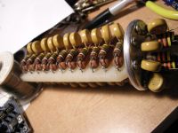
hears another exmple of this type of probe
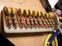
teravolt, Thu Apr 14 2011, 04:58AM
hears another exmple of this type of probe


Re: High voltage probe for O-scope, 1 of 2, ( DEVELOPMENT ).
Patrick, Thu Apr 14 2011, 05:31AM
Have you seen this?
I would like to get that type, in my hands to test, but i dont think i can settle for just what you describe. I need a tek, North star or ross enginneering one to look at, internally. I really need to replicate their type of probes.
Patrick, Thu Apr 14 2011, 05:31AM
Have you seen this?
I would like to get that type, in my hands to test, but i dont think i can settle for just what you describe. I need a tek, North star or ross enginneering one to look at, internally. I really need to replicate their type of probes.
Re: High voltage probe for O-scope, 1 of 2, ( DEVELOPMENT ).
teravolt, Thu Apr 14 2011, 02:12PM
the devider probe part is easy it is the compinsation box at the o-scope end is the kicker
teravolt, Thu Apr 14 2011, 02:12PM
the devider probe part is easy it is the compinsation box at the o-scope end is the kicker
Re: High voltage probe for O-scope, 1 of 2, ( DEVELOPMENT ).
Patrick, Thu Apr 14 2011, 04:35PM
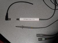
the HV probe itself is 1,000:1 while in series with a X10 probe, the total divsion ratio then becomes 10,000:1.

Yellow are copper "Park-like" Caps, Red are resistors. The bottom most section are where compensation and LV componets live.
 look here, internals of a P6013A, schematic and disassembeld
 And here, look at my northstar email qoute.
EDIT: remember, the NorthStars and others now have a factory calibration inside the probe that the end user cant change. And a single capacitor trim on the BNC end to scope. These are far improved from the defuct P6013A (or the P6014, P6015) that have which has 6 (and 8) adjustments all freq related.
Patrick, Thu Apr 14 2011, 04:35PM
teravolt wrote ...
the devider probe part is easy it is the compinsation box at the o-scope end is the kicker
well ok, in simulation i have had wild variation in any of the compensation techniques i have attempted, so i have taken a normal 10X probe and connected that to the bottom of the divider, why wouldnt this work? it seems like it should.the devider probe part is easy it is the compinsation box at the o-scope end is the kicker

the HV probe itself is 1,000:1 while in series with a X10 probe, the total divsion ratio then becomes 10,000:1.

Yellow are copper "Park-like" Caps, Red are resistors. The bottom most section are where compensation and LV componets live.
 look here, internals of a P6013A, schematic and disassembeld
 And here, look at my northstar email qoute.
 EDIT: remember, the NorthStars and others now have a factory calibration inside the probe that the end user cant change. And a single capacitor trim on the BNC end to scope. These are far improved from the defuct P6013A (or the P6014, P6015) that have which has 6 (and 8) adjustments all freq related.
Re: High voltage probe for O-scope, 1 of 2, ( DEVELOPMENT ).
Patrick, Sat Apr 16 2011, 06:46AM
I found this:
"Dan (or the Captain) just made a home brew probe that was extremely
interesting and had some modern design techniques behind it!! I wound not
be surprised if it easily outperformed the P6015...
Cheers, Terry "
Im still trying to find "Dan the Captain's" work.
Patrick, Sat Apr 16 2011, 06:46AM
I found this:

"Dan (or the Captain) just made a home brew probe that was extremely
interesting and had some modern design techniques behind it!! I wound not
be surprised if it easily outperformed the P6015...
Cheers, Terry "
Im still trying to find "Dan the Captain's" work.
Re: High voltage probe for O-scope, 1 of 2, ( DEVELOPMENT ).
Pinky's Brain, Sat Apr 16 2011, 01:58PM
He was at Eastern Voltage Research I see ... they had a HV divider on the old website resources, but that is no longer there. I don't remember exactly what was on the page and the wayback machine isn't cooperating. They do have schematics for a high voltage probe. Of course a physical description is more important than the schematic with just electronic components, but it's something :

Here is the original wayback machine page describing the divider, unfortunately the pictures have been lost to time :

Pinky's Brain, Sat Apr 16 2011, 01:58PM
He was at Eastern Voltage Research I see ... they had a HV divider on the old website resources, but that is no longer there. I don't remember exactly what was on the page and the wayback machine isn't cooperating. They do have schematics for a high voltage probe. Of course a physical description is more important than the schematic with just electronic components, but it's something :

Here is the original wayback machine page describing the divider, unfortunately the pictures have been lost to time :

Re: High voltage probe for O-scope, 1 of 2, ( DEVELOPMENT ).
teravolt, Sat Apr 16 2011, 05:10PM
Hi Patrick, I found some links that might be helpfull


let us know what you think
teravolt, Sat Apr 16 2011, 05:10PM
Hi Patrick, I found some links that might be helpfull


let us know what you think
Re: High voltage probe for O-scope, 1 of 2, ( DEVELOPMENT ).
Patrick, Sat Apr 16 2011, 05:14PM
OOooo Teravolt got in a ninja post!
I have seen all of the above links many times before teravolt except for the 88 page PDF one.
Patrick, Sat Apr 16 2011, 05:14PM
Pinky's Brain wrote ...
He was at Eastern Voltage Research I see ... they had a HV divider on the old website resources, but that is no longer there. I don't remember exactly what was on the page and the wayback machine isn't cooperating. They do have schematics for a high voltage probe. Of course a physical description is more important than the schematic with just electronic components, but it's something :
Ok, in that case I have seen his work related to this device. Maybe Teravolt will look at that compensation section.He was at Eastern Voltage Research I see ... they had a HV divider on the old website resources, but that is no longer there. I don't remember exactly what was on the page and the wayback machine isn't cooperating. They do have schematics for a high voltage probe. Of course a physical description is more important than the schematic with just electronic components, but it's something :
OOooo Teravolt got in a ninja post!

I have seen all of the above links many times before teravolt except for the 88 page PDF one.
Re: High voltage probe for O-scope, 1 of 2, ( DEVELOPMENT ).
teravolt, Mon Apr 18 2011, 04:33AM
well you obviously have much more experience with building hv probes so I shall be the student until you have not read what I can find on the net. these probes are not easy to design or they would not sell for 1000 plus. regretfully I have not built one of these probes but it would be nice to.
Re: High voltage probe for O-scope, 1 of 2, ( DEVELOPMENT ).
Patrick, Mon Apr 18 2011, 07:30AM
As one experiment is worth a thousand expert opinions. We will see if I know as much as I hope I do.
Patrick, Mon Apr 18 2011, 07:30AM
teravolt wrote ...
regretfully I have not built one of these probes but it would be nice to.
Then we shall do so.regretfully I have not built one of these probes but it would be nice to.
As one experiment is worth a thousand expert opinions. We will see if I know as much as I hope I do.
Re: High voltage probe for O-scope, 1 of 2, ( DEVELOPMENT ).
Patrick, Tue Apr 19 2011, 04:24AM
ok here is my most current attempt.
I was trying to PM Pinky's Brain, but get the "User not found" message?

This is an example of a standard probe modded to take BNC's on both ends, as per the blue boxes in the schematic pic below.

Basic physical layout, though now there would be three park RC's not the two seen above.
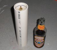
Pvc pipe, 2.4" OD, schedule 40, 0.160" wall thickness, 10.3 inches tall. this probe would be more similar to the VD NorthStars (not hand held like the Tek's or PVM's) as per Pinky's opinion, with 3mm per kv seperation from the terminal to nearest ground.

Notice that in the Teks (any of the p6013,14,15) they all share an internal capacitor leaf, plus the full length cylinder grounded shield. They also conduct the main current from the tip all the way through the cable to the comp box circuit.
The NorthStars, mine and the patent
all have the main current sent to a nearby ground, with the small current signal then going to the far off O-Scope.
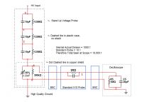
Schematic. Hopefully this will be flat from DC-5Mhz, even though the probe is rated past 150Mhz.
I hope the use of the standard modded probe will solve the coupling problem ive been having. I have been able in real circuits, and simulated circuits to get the initial division done, but then trying to get the signal to the O-scope has always involved other comp circuits which caused bazarre behavior, like frequency peaks, drops, tail offs on square waves, droops and so on.
Patrick, Tue Apr 19 2011, 04:24AM
ok here is my most current attempt.
I was trying to PM Pinky's Brain, but get the "User not found" message?

This is an example of a standard probe modded to take BNC's on both ends, as per the blue boxes in the schematic pic below.

Basic physical layout, though now there would be three park RC's not the two seen above.

Pvc pipe, 2.4" OD, schedule 40, 0.160" wall thickness, 10.3 inches tall. this probe would be more similar to the VD NorthStars (not hand held like the Tek's or PVM's) as per Pinky's opinion, with 3mm per kv seperation from the terminal to nearest ground.
Pinky's Brain wrote ...
To me it seems that a handheld probe is significantly harder to design than a standalone probe connected through a low induction copper strap. With a stand alone probe you can keep the electric field across the HV resistor uniform (like your capacitive hoops in the other thread) which simplifies modelling it's operation.
The moment you put a grounded metal shield around it which goes close to the tip the behaviour of the system becomes much harder to predict.

Notice that in the Teks (any of the p6013,14,15) they all share an internal capacitor leaf, plus the full length cylinder grounded shield. They also conduct the main current from the tip all the way through the cable to the comp box circuit.
The NorthStars, mine and the patent
all have the main current sent to a nearby ground, with the small current signal then going to the far off O-Scope.

Schematic. Hopefully this will be flat from DC-5Mhz, even though the probe is rated past 150Mhz.
I hope the use of the standard modded probe will solve the coupling problem ive been having. I have been able in real circuits, and simulated circuits to get the initial division done, but then trying to get the signal to the O-scope has always involved other comp circuits which caused bazarre behavior, like frequency peaks, drops, tail offs on square waves, droops and so on.
Re: High voltage probe for O-scope, 1 of 2, ( DEVELOPMENT ).
teravolt, Tue Apr 19 2011, 07:47PM
I like the one on the bottom it is simple and streight forward. in my nija poast one of those papers say that the capacitance has to have the same division ratio as the resistors wich makes sense. The P6013 are a bitch to calibrate and the frequency specrum on those are suto flat and probibly need special equipment. the copper peaces that you have added to your resistors are exalent electrostac shields but offer no parallel capatance to carry the AC component that we are trying to mesure. if you added a ring of capacitors around each oppen ereas betwean the electrostatic shields, say 15kv 30-100 pf disk or chip, and then used the example in the last schematic you might have a starting point you could put the bottom part of the divider at the base of your pvc tube. on the side the cabe that goes beween the p3016 and its compinsation box is a special foam coax and the center is like 3-5 mill to I asume to reduce the capance in the connction between them
Re: High voltage probe for O-scope, 1 of 2, ( DEVELOPMENT ).
Patrick, Tue Apr 19 2011, 08:32PM
Teravolt, read this patent with regards to the capacitience of each seriesed stage.
30-100pF is to much to get the 5Mhz, 70nS I need, capacitence is the enemy,I need only enough to equalize the division of the e-field.
then look at these:

The dinosaur P6013, P6014, P6015 probe series.
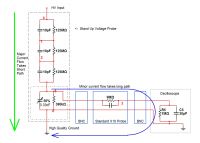
Northstar, Ross engineering, the patent, and my type of probe.
Patrick, Tue Apr 19 2011, 08:32PM
Teravolt, read this patent with regards to the capacitience of each seriesed stage.
30-100pF is to much to get the 5Mhz, 70nS I need, capacitence is the enemy,I need only enough to equalize the division of the e-field.
then look at these:

The dinosaur P6013, P6014, P6015 probe series.

Northstar, Ross engineering, the patent, and my type of probe.
Re: High voltage probe for O-scope, 1 of 2, ( DEVELOPMENT ).
teravolt, Wed Apr 20 2011, 05:01AM
I talked to one of our engineers today and the variable cap is for undershoot and overshoot adjustment. apparently you don't need much capacitance to get the effect you want. For an example he showed me a weird probe that has some cadock resistors surrounded by two large bowls and he said that by adusting the size of the bottom peace he can adjust the over or undershoot. The p6013 above uses the same princable. If you had a peace of metal tubing around the outside of your pvc tubing connected to ground. that may work to create the capacitance you need. or half and half where the top half of your probe connects to the top peace of tubing and the bottom half connected to ground. The northstar probe looks like the capacitors are physical capacitors in parallel with the divider resitors. If they are not then some how the capacitanceis created physicaly like you are trying to do and they are in parallel with the resistors.
The probe in the first page has resistors in series with each capacitor, this is for dampining ringing, probibly because the lenght of the probe probibly has a inductive component that becomes notiable at higher freq combined with the capacitor you are trying to create. He said the best way to lern about this stuff is by doing. I hope my ramblings make some sense so I the student will sit now.
Re: High voltage probe for O-scope, 1 of 2, ( DEVELOPMENT ).
teravolt, Wed Apr 20 2011, 05:27AM
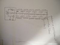
maby something like this
teravolt, Wed Apr 20 2011, 05:27AM
maby something like this

Re: High voltage probe for O-scope, 1 of 2, ( DEVELOPMENT ).
Patrick, Tue May 10 2011, 06:06AM
Found It !!!
Eastern Voltage Research 50MHz, 60kV probe.
]60kvdivider_fullschematic.pdf[/file]
I must admit it does look like it has modeled after this patent....
The only problem is -- I dont have any idea how the math works for the compensation section, or how to modify it for my purposes. Totally guessing and simulating at the moment.
EDIT: Im getting a -3dB roll off at 53MHz and -5 degrees at 5MHz in simulation, is this just a phase shift type circuit? Whatever it is, it works well and has only one adjustment, instead of 6 trimmers.
It is interesting that 82pf x 2 = 164pf / 7 = 23.4pf total input capacity. thats way more than mine. Soo maybe i could increase it quite abit.
Re: High voltage probe for O-scope, 1 of 2, ( DEVELOPMENT ).
Carl Pugh, Tue May 10 2011, 03:01PM
Could you use a capacitive voltage divider with no resistors?
There are applications where a small sphere is put in a tank with high voltage. The sphere is calibrated at low voltage and then used to measure high voltage.
BSEE from Heald College.
Definitely not a communist from Berkeley.
Re: High voltage probe for O-scope, 1 of 2, ( DEVELOPMENT ).
Patrick, Tue May 10 2011, 06:16PM
Patrick, Tue May 10 2011, 06:16PM
Carl Pugh wrote ...
Could you use a capacitive voltage divider with no resistors?
There are applications where a small sphere is put in a tank with high voltage. The sphere is calibrated at low voltage and then used to measure high voltage.
I dont know, i tried this but it seemed difficult to calibrate, and i was getting alot of bogus field division external to the device. And they dont work below 400Hz to well.Could you use a capacitive voltage divider with no resistors?
There are applications where a small sphere is put in a tank with high voltage. The sphere is calibrated at low voltage and then used to measure high voltage.
Carl Pugh wrote ...
BSEE from Heald College.
Definitely not a communist from Berkeley.
I was being facetious.BSEE from Heald College.
Definitely not a communist from Berkeley.
Re: High voltage probe for O-scope, 1 of 2, ( DEVELOPMENT ).
Patrick, Thu May 12 2011, 12:33AM
[Gen 5, Type 3, Mod 60, Rev I, Ver 3.0, Attempt 11] for HV O-scope Probes. (Most Current)
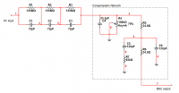
My planned circuit. [oops! C4 is pico should be nano]

(C1 should be nano) Heres the compensation ive been planning and simulating....(from EVR)
At 54Mhz im getting about -44 degrees on the bode plotter.
Magnitude roll off. (This looks real good)
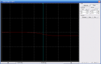
Phase angle. (This is ok)
EDIT: Im hoping someone else could simulate this circuit here:
, to verify some of the math related to the roll off.
ALL problems *SEEM* to be solved, maybe the end of this project is in sight? Now that ive said this, ill probably discover some other problem.
Patrick, Thu May 12 2011, 12:33AM
[Gen 5, Type 3, Mod 60, Rev I, Ver 3.0, Attempt 11] for HV O-scope Probes. (Most Current)

My planned circuit. [oops! C4 is pico should be nano]

(C1 should be nano) Heres the compensation ive been planning and simulating....(from EVR)
At 54Mhz im getting about -44 degrees on the bode plotter.

Magnitude roll off. (This looks real good)

Phase angle. (This is ok)
EDIT: Im hoping someone else could simulate this circuit here:
, to verify some of the math related to the roll off.
ALL problems *SEEM* to be solved, maybe the end of this project is in sight? Now that ive said this, ill probably discover some other problem.

Re: High voltage probe for O-scope, 1 of 2, ( DEVELOPMENT ).
Pinky's Brain, Thu May 12 2011, 01:52PM
Does anyone have a rule of thumb calculation for capacity to environment for a vertical piece of wire at a given distance above a ground plane?
Pinky's Brain, Thu May 12 2011, 01:52PM
Does anyone have a rule of thumb calculation for capacity to environment for a vertical piece of wire at a given distance above a ground plane?
Re: High voltage probe for O-scope, 1 of 2, ( DEVELOPMENT ).
teravolt, Thu May 12 2011, 02:03PM
I like it Patrick and it is agood starting point, C4 should also be variable I think. I was looking into surface mount components witch may have a flatter frequency responce vs descreate components what do you think. just keep the attenuation ratio the same in each branch and reduce inductance any way you can.
Re: High voltage probe for O-scope, 1 of 2, ( DEVELOPMENT ).
Patrick, Thu May 12 2011, 02:16PM
I put in an email to Eastern Voltage Research in regards to them re-posting that orginal web page which is incomplete on the Wayback Machine. So hopefully they will put up pics and docs related to how that compensation circuit works. But I have a way better understanding now then I did 2 days ago on this matter, so it does in simulation look like its working.
EDIT: Wow! I have been seeing the "views" number tick up quite a bit on this thread, so there must be some interest in this device.
Re: High voltage probe for O-scope, 1 of 2, ( DEVELOPMENT ).
Pinky's Brain, Sat May 14 2011, 03:17PM
Found some formulas for capacitance to ground :


1 pF capacitance to ground in between each of the stages of the high voltage arm seems a decent if slightly pessimistic approximation.
Also found a divider which shows nicely why it's better to create the distributed capacitance by structural methods with the shielding than with individual capacitors.

The reason they use so many capacitors in a circular string at each stage is to minimize wire inductance. If you build it structurally like for instance with the dual layer shielding Teravolt proposed you automatically get low inductance (a wide diameter hollow conductor has lower inductance than a narrow wire) at much lower cost. Although it will be hard to control insulation thickness to get equal capacitance per stage, flaring out the shield into two discs with an insulator in between will make this easier.
Pinky's Brain, Sat May 14 2011, 03:17PM
Patrick wrote ...
Found It !!!
Dude ... that's what I linked before!!! :)Found It !!!
wrote ...
It is interesting that 82pf x 2 = 164pf / 7 = 23.4pf total input capacity. thats way more than mine. Soo maybe i could increase it quite abit.
I think I said that before, basically the distributed capacitance has to drown out the capacitance of divider to ground.It is interesting that 82pf x 2 = 164pf / 7 = 23.4pf total input capacity. thats way more than mine. Soo maybe i could increase it quite abit.
Found some formulas for capacitance to ground :


1 pF capacitance to ground in between each of the stages of the high voltage arm seems a decent if slightly pessimistic approximation.
Also found a divider which shows nicely why it's better to create the distributed capacitance by structural methods with the shielding than with individual capacitors.

The reason they use so many capacitors in a circular string at each stage is to minimize wire inductance. If you build it structurally like for instance with the dual layer shielding Teravolt proposed you automatically get low inductance (a wide diameter hollow conductor has lower inductance than a narrow wire) at much lower cost. Although it will be hard to control insulation thickness to get equal capacitance per stage, flaring out the shield into two discs with an insulator in between will make this easier.
Re: High voltage probe for O-scope, 1 of 2, ( DEVELOPMENT ).
Patrick, Sat May 14 2011, 04:55PM
Patrick, Sat May 14 2011, 04:55PM
Pinky's Brain wrote ...
I didnt relise what the significance of your link was, until i simulated the compensation circuit alone.Patrick wrote ...
Found It !!!
Dude ... that's what I linked before!!! :)Found It !!!
Re: High voltage probe for O-scope, 1 of 2, ( DEVELOPMENT ).
Patrick, Sun May 15 2011, 04:14PM
I have just been informed that Daniel McCauley, of Eastern voltage Research that the pics in question are archived and not immeadiatley available. hopefully he can find them when he has some time.
Patrick, Sun May 15 2011, 04:14PM
I have just been informed that Daniel McCauley, of Eastern voltage Research that the pics in question are archived and not immeadiatley available. hopefully he can find them when he has some time.
Re: High voltage probe for O-scope, 1 of 2, ( DEVELOPMENT ).
Patrick, Wed Jul 27 2011, 12:14PM
New work completed so far...
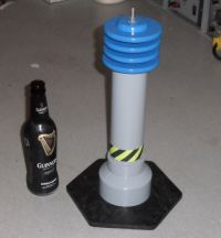
Insulator is acrylic should be good for 50kV+
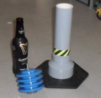
Patrick, Wed Jul 27 2011, 12:14PM
New work completed so far...

Insulator is acrylic should be good for 50kV+

Re: High voltage probe for O-scope, 1 of 2, ( DEVELOPMENT ).
Patrick, Sun Sept 04 2011, 02:06AM
Ok new construction and assembly is about to begin, so we will see if my probes work or not shortly.
Based on my own research and experiments, Ross Engineerng, Northstar, Tektronics, Caddock and Marco Denicolai's work ive come up with this as the basic building block:
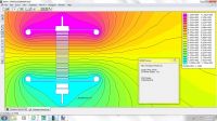
The resistor's V drop is linearized with the cap plates, and grading rings.
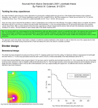
Marco Denicolai's explanation of his 20 liter water HV probe (600kV).
[Note what i have highlighted in green.]
His PDF is here:
]hvprobemd.pdf[/file]
Marco's tesla and thesis site:
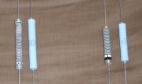
My Hv resistors.
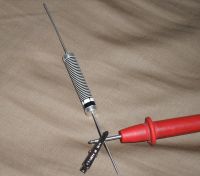
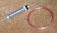
Patrick, Sun Sept 04 2011, 02:06AM
Ok new construction and assembly is about to begin, so we will see if my probes work or not shortly.
Based on my own research and experiments, Ross Engineerng, Northstar, Tektronics, Caddock and Marco Denicolai's work ive come up with this as the basic building block:

The resistor's V drop is linearized with the cap plates, and grading rings.

Marco Denicolai's explanation of his 20 liter water HV probe (600kV).
[Note what i have highlighted in green.]
His PDF is here:
]hvprobemd.pdf[/file]
Marco's tesla and thesis site:


My Hv resistors.


Re: High voltage probe for O-scope, 1 of 2, ( DEVELOPMENT ).
Pinky's Brain, Sun Sept 04 2011, 10:21AM
Never saw a high impedance liquid divider before, usually liquid dividers are low impedance affairs.
Pinky's Brain, Sun Sept 04 2011, 10:21AM
Never saw a high impedance liquid divider before, usually liquid dividers are low impedance affairs.
Re: High voltage probe for O-scope, 1 of 2, ( DEVELOPMENT ).
Tetris, Sun Sept 04 2011, 01:33PM
Capacitors sort of scare me. Even flash caps. I still feel uncomfortable using them and typically handle them with much more care than I did yesterday around my NST. But how is that a sillyscope probe? Hm I need a new one, mine is broken.
Tetris, Sun Sept 04 2011, 01:33PM
Capacitors sort of scare me. Even flash caps. I still feel uncomfortable using them and typically handle them with much more care than I did yesterday around my NST. But how is that a sillyscope probe? Hm I need a new one, mine is broken.
Re: High voltage probe for O-scope, 1 of 2, ( DEVELOPMENT ).
Patrick, Sun Sept 04 2011, 04:27PM
Patrick, Sun Sept 04 2011, 04:27PM
HighVoltageChick wrote ...
Capacitors sort of scare me. Even flash caps. I still feel uncomfortable using them and typically handle them with much more care than I did yesterday around my NST. But how is that a sillyscope probe? Hm I need a new one, mine is broken.
You can get the standard 10X probes on ebay, 2 probes for $15-40. My design here is for a specialized application.Capacitors sort of scare me. Even flash caps. I still feel uncomfortable using them and typically handle them with much more care than I did yesterday around my NST. But how is that a sillyscope probe? Hm I need a new one, mine is broken.
Re: High voltage probe for O-scope, 1 of 2, ( DEVELOPMENT ).
Patrick, Mon Sept 26 2011, 08:05AM
New progress.
These next few pics show the construction of what i call the "High Voltage RC Element", this device is a SSX39 MG resistor,
125 Mohms in parallel with a coaxial 4.9-5.2 pF oil capacitor, both are meant to withstand 14 kV. 3 of these "elements" will be in series to obtain a 42 kV probe of 375 Mohms, at 1.5 to 1.7 pF. I just pray the field distrubution and capacitence is enough, the Northstars have 10 pF for a similar spec'ed probe. The bottom most plate is insulated from the resistor body, as the voltage drop beneath it is 800 volts less then the plate. This probe will be oil filled and have a 10,000:1 division ratio.

Sheet metal and copper ring.
Plates of steel and copper soldered and epoxied, then attatched as per the FEMM model for field distrubution.
Temporary hot glue mock up to test fit and funtion, this will be redone in oil proof epoxy soon.
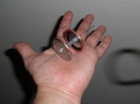
Seen here in my hand.

The resistor's V drop is linearized with the cap plates, and grading rings.

Zoey, best dog ever, on quality control.
Patrick, Mon Sept 26 2011, 08:05AM
New progress.
These next few pics show the construction of what i call the "High Voltage RC Element", this device is a SSX39 MG resistor,
125 Mohms in parallel with a coaxial 4.9-5.2 pF oil capacitor, both are meant to withstand 14 kV. 3 of these "elements" will be in series to obtain a 42 kV probe of 375 Mohms, at 1.5 to 1.7 pF. I just pray the field distrubution and capacitence is enough, the Northstars have 10 pF for a similar spec'ed probe. The bottom most plate is insulated from the resistor body, as the voltage drop beneath it is 800 volts less then the plate. This probe will be oil filled and have a 10,000:1 division ratio.

Sheet metal and copper ring.

Plates of steel and copper soldered and epoxied, then attatched as per the FEMM model for field distrubution.

Temporary hot glue mock up to test fit and funtion, this will be redone in oil proof epoxy soon.

Seen here in my hand.

The resistor's V drop is linearized with the cap plates, and grading rings.

Zoey, best dog ever, on quality control.
Re: High voltage probe for O-scope, 1 of 2, ( DEVELOPMENT ).
Patrick, Tue Sept 27 2011, 04:57PM
Compensation circuits of various types and methods, and my own original research from a book.

From John F. Powers thesis, 1986.
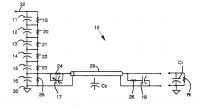
From the patent US5107201.

Dan McCauley's device from EVR.

Tektronix P6015A probe schematic.

Tektronix P6013 probe schematic.
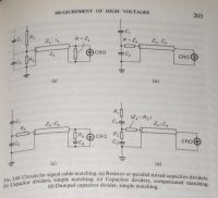
Exceprts from "High Voltage Engineering Fundamentals" E. Kuffel, W.S. Zaengl. Pergamon Press.
[isbn: 0-08-024213-8]
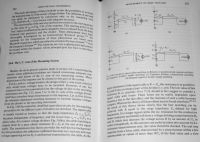
Exceprts from "High Voltage Engineering Fundamentals" E. Kuffel, W.S. Zaengl. Pergamon Press.
[isbn: 0-08-024213-8]
Patrick, Tue Sept 27 2011, 04:57PM
Compensation circuits of various types and methods, and my own original research from a book.

From John F. Powers thesis, 1986.

From the patent US5107201.

Dan McCauley's device from EVR.

Tektronix P6015A probe schematic.

Tektronix P6013 probe schematic.

Exceprts from "High Voltage Engineering Fundamentals" E. Kuffel, W.S. Zaengl. Pergamon Press.
[isbn: 0-08-024213-8]

Exceprts from "High Voltage Engineering Fundamentals" E. Kuffel, W.S. Zaengl. Pergamon Press.
[isbn: 0-08-024213-8]
Re: High voltage probe for O-scope, 1 of 2, ( DEVELOPMENT ).
jpsmith123, Wed Sept 28 2011, 12:35PM
Patrick are those resistors made by EBG?
If so the data sheet says this: "Our resistors are designed for operation in air and not agressive [sic] atmospheres. For special
applications (i.e. oil, casting, moulding, SF6, etc.) please contact your nearest EBG representative."
I don't know why there should be any issues with oil or an encapsulant, but have you asked them about that?
Re: High voltage probe for O-scope, 1 of 2, ( DEVELOPMENT ).
Patrick, Wed Sept 28 2011, 03:49PM
Yes already cleared that up, oil is fine. Ive had contact will Del/Spellman HV corp and EBG they all say oil is fine, ive figuered out a way to leave the silicone coating on and still find the lower drop end, so that resistor will be the last one you see with the white and black stripes.
EDIT: does " [sic] " mean "said in context" ?
Patrick, Wed Sept 28 2011, 03:49PM
jpsmith123 wrote ...
Patrick are those resistors made by EBG?
If so the data sheet says this: "Our resistors are designed for operation in air and not agressive [sic] atmospheres. For special
applications (i.e. oil, casting, moulding, SF6, etc.) please contact your nearest EBG representative."
I don't know why there should be any issues with oil or an encapsulant, but have you asked them about that?
Yes already cleared that up, oil is fine. Ive had contact will Del/Spellman HV corp and EBG they all say oil is fine, ive figuered out a way to leave the silicone coating on and still find the lower drop end, so that resistor will be the last one you see with the white and black stripes.
EDIT: does " [sic] " mean "said in context" ?
Re: High voltage probe for O-scope, 1 of 2, ( DEVELOPMENT ).
jpsmith123, Wed Sept 28 2011, 05:20PM
According to Wikipedia: Sic is a Latin word that means "thus" or, in writing, "it was thus in the source material".
Basically I just used it to indicate that the misspelled word appearing in the quoted text was that way in the original text and not my mistake.
The usual usage is described here:

BTW I think I will use some of those same resistors in my voltage multiplier. I guess it's ok to encapsulate them in silicone rubber?
jpsmith123, Wed Sept 28 2011, 05:20PM
According to Wikipedia: Sic is a Latin word that means "thus" or, in writing, "it was thus in the source material".
Basically I just used it to indicate that the misspelled word appearing in the quoted text was that way in the original text and not my mistake.
The usual usage is described here:

BTW I think I will use some of those same resistors in my voltage multiplier. I guess it's ok to encapsulate them in silicone rubber?
Re: High voltage probe for O-scope, 1 of 2, ( DEVELOPMENT ).
Patrick, Wed Sept 28 2011, 09:42PM
Patrick, Wed Sept 28 2011, 09:42PM
jpsmith123 wrote ...
According to Wikipedia: Sic is a Latin word that means "thus" or, in writing, "it was thus in the source material".
Basically I just used it to indicate that the misspelled word appearing in the quoted text was that way in the original text and not my mistake.
The usual usage is described here:

Didnt know that...According to Wikipedia: Sic is a Latin word that means "thus" or, in writing, "it was thus in the source material".
Basically I just used it to indicate that the misspelled word appearing in the quoted text was that way in the original text and not my mistake.
The usual usage is described here:

jpsmith123 wrote ...
BTW I think I will use some of those same resistors in my voltage multiplier. I guess it's ok to encapsulate them in silicone rubber?
yes silicone is fine, the only hazard with ridgid epoxy is that a gap can form between the resistor body and encapsulant which then becomes atmosphere filled and causes corona problems. You can avoid this problem by using dimensionally/thermally stable epoxy or just soft silicone. (Or if your a real man you can use oil)BTW I think I will use some of those same resistors in my voltage multiplier. I guess it's ok to encapsulate them in silicone rubber?
Re: High voltage probe for O-scope, 1 of 2, ( DEVELOPMENT ).
Patrick, Sat Oct 01 2011, 06:43AM
Three vertical seriesed RC elements good for 42 kV at 50 MhZ, 2pF, 375 Mohms. [ Dimensions: 2.3 in Dia, 8 inches tall. ]
My apologies for the crappy Jpg output, ill redo it in the morning.

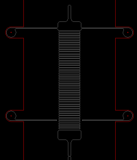
Resistor and cap in grey, support ribs in red, support ribs are FR4 circuit board material.
Patrick, Sat Oct 01 2011, 06:43AM
Three vertical seriesed RC elements good for 42 kV at 50 MhZ, 2pF, 375 Mohms. [ Dimensions: 2.3 in Dia, 8 inches tall. ]
My apologies for the crappy Jpg output, ill redo it in the morning.


Resistor and cap in grey, support ribs in red, support ribs are FR4 circuit board material.
Re: High voltage probe for O-scope, 1 of 2, ( DEVELOPMENT ).
Patrick, Mon Oct 17 2011, 01:56AM
For the lower voltage caps i will use 400 Volt poplypropylene and silver mica caps , they have low loss and good freq response. should arrive in a few days.
Patrick, Mon Oct 17 2011, 01:56AM
For the lower voltage caps i will use 400 Volt poplypropylene and silver mica caps , they have low loss and good freq response. should arrive in a few days.
Re: High voltage probe for O-scope, 1 of 2, ( DEVELOPMENT ).
Herr Zapp, Mon Oct 17 2011, 05:27AM
Patrick -
For each of your R-C modules, the lower capacitor plate/gradient ring is "floating", not electrically connected to the lower resistor terminal. Why is this? Is there no danger of corona between the sharp edges of the clearance hole in the "washer" and the resistance element on the OD of the resistor?
How did you determine the appropriate distance between the lower gradient ring and the lower resistor terminal? Was this distance based only on the desired capacitance between the plates?
In the similar R-C module construction shown in the J. Power thesis, the gradient rings are electrically & mechanically connected to each end of the resistor.
Herr Zapp
Re: High voltage probe for O-scope, 1 of 2, ( DEVELOPMENT ).
Patrick, Mon Oct 17 2011, 05:31AM
look here for the construction/project thread ->
Patrick, Mon Oct 17 2011, 05:31AM
Herr Zapp wrote ...
Patrick -
For each of your R-C modules, the lower capacitor plate/gradient ring is "floating", not electrically connected to the lower resistor terminal. Why is this? Is there no danger of corona between the sharp edges of the clearance hole in the "washer" and the resistance element on the OD of the resistor?
First, both plates are connected to the ends of the resistor. in order to optimize the field geometry so the mid point V-drop of the resistor matches the location of the Mid point E-field of the same cap i needed about 3mm of length on one end past the cap plate. it is attatched to the resistor, not floating, also there is 4000volts of insulation between the plate and resistor body, no corona danger at all, only 800 volts difference is present.Patrick -
For each of your R-C modules, the lower capacitor plate/gradient ring is "floating", not electrically connected to the lower resistor terminal. Why is this? Is there no danger of corona between the sharp edges of the clearance hole in the "washer" and the resistance element on the OD of the resistor?
Herr Zapp wrote ...
How did you determine the appropriate distance between the lower gradient ring and the lower resistor terminal? Was this distance based only on the desired capacitance between the plates?
No, it wasnt the capacitence that was the deciding factor, it was the V-drop/E-field location, the capacitance is merely incidental, i worry 4-5pF is to low.How did you determine the appropriate distance between the lower gradient ring and the lower resistor terminal? Was this distance based only on the desired capacitance between the plates?
Herr Zapp wrote ...
In the similar R-C module construction shown in the J. Power thesis, the gradient rings are electrically & mechanically connected to each end of the resistor.
Yes, as are mine.In the similar R-C module construction shown in the J. Power thesis, the gradient rings are electrically & mechanically connected to each end of the resistor.
look here for the construction/project thread ->

Re: High voltage probe for O-scope, 1 of 2, ( DEVELOPMENT ).
Herr Zapp, Mon Oct 17 2011, 03:50PM
Patrick -
Thanks for the clarification; I've have been following your probe development with interest. The FEMM model seemed to show the lower plate as electrically, floating and none of the photographs show a close-up of how the plates are physically connected to the resistor. At the bottom end of each module, some of the photos show what looks like pink tape wound around the resistor body, under the epoxy. Looking closely at the rest of the photos I now see the little jumper wires connecting the resistor terminals to the cap plates, partially buried in all the goo.
Have you get your calibrator figured out yet? That will be essential for "qualifying" your probe design.
Herr Zapp
Re: High voltage probe for O-scope, 1 of 2, ( DEVELOPMENT ).
Patrick, Mon Oct 17 2011, 04:05PM
Patrick, Mon Oct 17 2011, 04:05PM
Herr Zapp wrote ...
Patrick -
Thanks for the clarification; I've have been following your probe development with interest. The FEMM model seemed to show the lower plate as electrically, floating and none of the photographs show a close-up of how the plates are physically connected to the resistor. At the bottom end of each module, some of the photos show what looks like pink tape wound around the resistor body, under the epoxy. Looking closely at the rest of the photos I now see the little jumper wires connecting the resistor terminals to the cap plates, partially buried in all the goo.
Yeah in the FEMM model you can specify that the lines enclosing a shape, are at a certain voltage, with out "wires" being visible.Patrick -
Thanks for the clarification; I've have been following your probe development with interest. The FEMM model seemed to show the lower plate as electrically, floating and none of the photographs show a close-up of how the plates are physically connected to the resistor. At the bottom end of each module, some of the photos show what looks like pink tape wound around the resistor body, under the epoxy. Looking closely at the rest of the photos I now see the little jumper wires connecting the resistor terminals to the cap plates, partially buried in all the goo.
Herr Zapp wrote ...
Have you get your calibrator figured out yet? That will be essential for "qualifying" your probe design.
Herr Zapp
Great minds think alike.... and no im trying to get that figured out now.Have you get your calibrator figured out yet? That will be essential for "qualifying" your probe design.
Herr Zapp
Print this page