Chris Russell 29 May : 19:36
This week, we have another gem from the archives: WaveRider's low power 433 MHz BPSK data transmission system.
This week, we have another gem from the archives: WaveRider's low power 433 MHz BPSK data transmission system. WaveRider single-handedly designed and implemented a complete data transmission system, using a highly efficient method of modulation. He's also obviously gone through extreme pains to document the entire project thoroughly. This is a special treat for those of us who enjoy telecommunications as a hobby.
Feel free to stop by the thread and let WaveRider know what you think. And, as always, feel free to send me a PM with suggestions for next week's featured project.
Additional Pictures:


Feel free to stop by the thread and let WaveRider know what you think. And, as always, feel free to send me a PM with suggestions for next week's featured project.
WaveRider wrote ...
It's been a while since I have done a radio project. So, I thought I would experiment with data transmission using BPSK (Binary Phase Shift Keying) on the 433 MHz European ISM band.
What's so special about BPSK?
Most commercial systems seem to use frequency shift keying (FSK) or some form of on-off keying (OOK). I wanted to explore the possibilities of constructing a simple system for binary phase shift keying (BPSK). Binary phase shift keying is a form of modulation that is very "power efficient." This means that to achieve a certain bit error rate, the required signal to noise ratio is lower than that required by, e.g., frequency shift keying or on-off keying. BPSK (or QPSK) is often the modulation mode of choice for deep space probes where power consumption must be minimised and signal path losses are enormous. See graphic (taken from ) for comparison of error rates....

Why 433.92 MHz?
Besides sitting in the middle of the 433MHz European ISM (industrial, scientific and medical) band, it is also in the amateur 70cm band, so parts were easy to get and it can be modified to operate under amateur radio rules. For those in the US, I think this band also falls under Part 15 of FCC regulations for low-power communications devices. Also, the local oscillators use of-the-shelf SAW resonators instead of a PLL synthesizer. This simplifies the design greatly (at the expense of having to operate on a fixed frequency).
What will the transmitter power be?
Operating below 10mW in this band is permitted without a license. I plan to limit the emissions to somewhat less than this. Many garage door openers and automotive key fobs seem to operate in this band (altho' at much below this power level). Hopefully this won't mean intolerable interference in my experiments!
First step: The receiver design
Since the receiver design is more challenging than the transmitter, I started off there. Here is a block diagram of my proposed receiver.

I am basing the system around the Philips SA639 RF/IF subsystem chip, which is really designed for FSK systems, using a 10.7MHz IF. I managed to find a 500kHz bandwidth ceramic IF filter which should allow upwards of 384kbit/sec communications. BPSK demodulation is not as easy as FSK. Basically, we need to add a carrier regeneration system (a PLL) for demodulating the BPSK signal coherently. I do this with a simple "squaring loop" which doubles the IF carrier frequency. A NE564 PLL/VCO system is the heart of this.
The system
The received signal enters the system (as you would expect ) at the antenna input. A low noise amplifier, based on the BFR540 NPN transistor amplifies the antenna signal. I was a bit torn about whether to put the microstrip-based band/image-reject filter before the low noise amplifier. If I put the filter before the amplifier, the filter insertion loss will kill the noise figure of the system. However, putting the filter after the amplifier increases the chances of amplifier overload by strong out-of-band signals. I opted for putting the filter after the amplifier. I will rely on the antenna system to reduce out-of-band signals. Plus, the BFR540 amplifier as I have designed it should be able to withstand -20dBm on the input terminals without saturating.
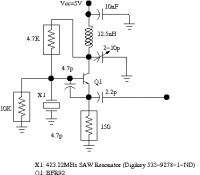
The next stage is the downconverting mixer. I found a SAW resonator for 423.22MHz which is exactly 10.7MHz away from 433.92MHz. Hence, the local oscillator (based on a BFR92 transistor) fed to the mixer (part of the SA639 chip) downconverts perfectly to 10.7MHz. The ceramic IF filter passes a sharply defined 500kHz channel to the
first IF amp and limiter.
At this point, we split off the signal to the second mixer as well as a push-push active frequency doubler. The output of the doubler is passed through a 21.4MHz (second harmonic) bandpass filter (with a band-stop notch at 10.7MHz) to the PLL carrier regeneration circuit. The 21.4MHz signal is divided by 2 using a flip-flop. After a phase correction and level adjusting circuit, the regenerated carrier is fed to the final mixer, where it is mixed with the original amplitude limited IF signal. The output will be the original BPSK digital data signal (a 250kHz low-pass filter on the output remives any residual RF). A schmitt trigger squares up the output and produces a TTL compatible signal.
I am hoping for a BER at 384kbit/sec of under 10e-6 with -106dBm input at the antenna terminals (in the absence of other interfering transmitters).
It's been a while since I have done a radio project. So, I thought I would experiment with data transmission using BPSK (Binary Phase Shift Keying) on the 433 MHz European ISM band.
What's so special about BPSK?
Most commercial systems seem to use frequency shift keying (FSK) or some form of on-off keying (OOK). I wanted to explore the possibilities of constructing a simple system for binary phase shift keying (BPSK). Binary phase shift keying is a form of modulation that is very "power efficient." This means that to achieve a certain bit error rate, the required signal to noise ratio is lower than that required by, e.g., frequency shift keying or on-off keying. BPSK (or QPSK) is often the modulation mode of choice for deep space probes where power consumption must be minimised and signal path losses are enormous. See graphic (taken from
 ) for comparison of error rates....
Why 433.92 MHz?
Besides sitting in the middle of the 433MHz European ISM (industrial, scientific and medical) band, it is also in the amateur 70cm band, so parts were easy to get and it can be modified to operate under amateur radio rules. For those in the US, I think this band also falls under Part 15 of FCC regulations for low-power communications devices. Also, the local oscillators use of-the-shelf SAW resonators instead of a PLL synthesizer. This simplifies the design greatly (at the expense of having to operate on a fixed frequency).
What will the transmitter power be?
Operating below 10mW in this band is permitted without a license. I plan to limit the emissions to somewhat less than this. Many garage door openers and automotive key fobs seem to operate in this band (altho' at much below this power level). Hopefully this won't mean intolerable interference in my experiments!
First step: The receiver design
Since the receiver design is more challenging than the transmitter, I started off there. Here is a block diagram of my proposed receiver.

I am basing the system around the Philips SA639 RF/IF subsystem chip, which is really designed for FSK systems, using a 10.7MHz IF. I managed to find a 500kHz bandwidth ceramic IF filter which should allow upwards of 384kbit/sec communications. BPSK demodulation is not as easy as FSK. Basically, we need to add a carrier regeneration system (a PLL) for demodulating the BPSK signal coherently. I do this with a simple "squaring loop" which doubles the IF carrier frequency. A NE564 PLL/VCO system is the heart of this.
The system
The received signal enters the system (as you would expect
 ) at the antenna input. A low noise amplifier, based on the BFR540 NPN transistor amplifies the antenna signal. I was a bit torn about whether to put the microstrip-based band/image-reject filter before the low noise amplifier. If I put the filter before the amplifier, the filter insertion loss will kill the noise figure of the system. However, putting the filter after the amplifier increases the chances of amplifier overload by strong out-of-band signals. I opted for putting the filter after the amplifier. I will rely on the antenna system to reduce out-of-band signals. Plus, the BFR540 amplifier as I have designed it should be able to withstand -20dBm on the input terminals without saturating.
The next stage is the downconverting mixer. I found a SAW resonator for 423.22MHz which is exactly 10.7MHz away from 433.92MHz. Hence, the local oscillator (based on a BFR92 transistor) fed to the mixer (part of the SA639 chip) downconverts perfectly to 10.7MHz. The ceramic IF filter passes a sharply defined 500kHz channel to the
first IF amp and limiter.
At this point, we split off the signal to the second mixer as well as a push-push active frequency doubler. The output of the doubler is passed through a 21.4MHz (second harmonic) bandpass filter (with a band-stop notch at 10.7MHz) to the PLL carrier regeneration circuit. The 21.4MHz signal is divided by 2 using a flip-flop. After a phase correction and level adjusting circuit, the regenerated carrier is fed to the final mixer, where it is mixed with the original amplitude limited IF signal. The output will be the original BPSK digital data signal (a 250kHz low-pass filter on the output remives any residual RF). A schmitt trigger squares up the output and produces a TTL compatible signal.
I am hoping for a BER at 384kbit/sec of under 10e-6 with -106dBm input at the antenna terminals (in the absence of other interfering transmitters).
Additional Pictures:


This news item is from 4hv.org
https://4hv.org/news.php?extend.35
Print this page
