If you need assistance, please send an email to forum at 4hv dot org. To ensure your email is not marked as spam, please include the phrase "4hv help" in the subject line. You can also find assistance via IRC, at irc.shadowworld.net, room #hvcomm.
Support 4hv.org!
Donate:
4hv.org is hosted on a dedicated server. Unfortunately, this server costs and we rely on the help of site members to keep 4hv.org running. Please consider donating. We will place your name on the thanks list and you'll be helping to keep 4hv.org alive and free for everyone. Members whose names appear in red bold have donated recently. Green bold denotes those who have recently donated to keep the server carbon neutral.
Special Thanks To:
Aaron Holmes
Aaron Wheeler
Adam Horden
Alan Scrimgeour
Andre
Andrew Haynes
Anonymous000
asabase
Austin Weil
barney
Barry
Bert Hickman
Bill Kukowski
Blitzorn
Brandon Paradelas
Bruce Bowling
BubeeMike
Byong Park
Cesiumsponge
Chris F.
Chris Hooper
Corey Worthington
Derek Woodroffe
Dalus
Dan Strother
Daniel Davis
Daniel Uhrenholt
datasheetarchive
Dave Billington
Dave Marshall
David F.
Dennis Rogers
drelectrix
Dr. John Gudenas
Dr. Spark
E.TexasTesla
eastvoltresearch
Eirik Taylor
Erik Dyakov
Erlend^SE
Finn Hammer
Firebug24k
GalliumMan
Gary Peterson
George Slade
GhostNull
Gordon Mcknight
Graham Armitage
Grant
GreySoul
Henry H
IamSmooth
In memory of Leo Powning
Jacob Cash
James Howells
James Pawson
Jeff Greenfield
Jeff Thomas
Jesse Frost
Jim Mitchell
jlr134
Joe Mastroianni
John Forcina
John Oberg
John Willcutt
Jon Newcomb
klugesmith
Leslie Wright
Lutz Hoffman
Mads Barnkob
Martin King
Mats Karlsson
Matt Gibson
Matthew Guidry
mbd
Michael D'Angelo
Mikkel
mileswaldron
mister_rf
Neil Foster
Nick de Smith
Nick Soroka
nicklenorp
Nik
Norman Stanley
Patrick Coleman
Paul Brodie
Paul Jordan
Paul Montgomery
Ped
Peter Krogen
Peter Terren
PhilGood
Richard Feldman
Robert Bush
Royce Bailey
Scott Fusare
Scott Newman
smiffy
Stella
Steven Busic
Steve Conner
Steve Jones
Steve Ward
Sulaiman
Thomas Coyle
Thomas A. Wallace
Thomas W
Timo
Torch
Ulf Jonsson
vasil
Vaxian
vladi mazzilli
wastehl
Weston
William Kim
William N.
William Stehl
Wesley Venis
The aforementioned have contributed financially to the continuing triumph of 4hv.org. They are deserving of my most heartfelt thanks.
Registered Member #10
Joined: Thu Feb 02 2006, 09:45AM
Location: Bunbury, Australia
Posts: 1424
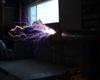
This follows on from investigations into a method to monitor the polarity of individual sparks and streamers in the High speed Tesla spark photography thread. I found that one could make a very effective and simple monitor with two LED's in anti-parallel and two 10 ohm resistors. This seems to be a rather bizarre combination of values which should make the LED's blow from overvoltage and over current but the red LED's haven't blown yet with solid 2 foot sparks from my 4 MOT Tesla coil. They are quite bright considering that they are only responding to bursts of microsecond pulses that make up a TC streamer ring up, strike and ring down. Note that you can't run the LED's off DC without putting about 0.4A through the 10 ohm resistor (=4W) and burning it up rapidly.
Pics show 1 circuit diagram, 2 actual low inductance wiring and 3 in use with a Tesla coil. The TC shot actually has them at both ends but the toroid end was mis-wired . 4 shows a high speed streak camera view of the negative strike and alternating polarity ringdown of sparks (which are not very visible to the camera)
Next post I will show ignition coil sparks and spark arresters.
Registered Member #10
Joined: Thu Feb 02 2006, 09:45AM
Location: Bunbury, Australia
Posts: 1424
Well, it gets weirder.
Photo 1 Main resistor 10 ohms, no shunt resistor. Still OK. Photo 2 No resistors at all You don't need the resistors at all. Well at least for ignition coil stuff. Photo 3 Actually I have known about this for 3 years. Here is my flyback inverter running of a 2N3055 (remember them?) and two antiparallel LED's taking the spark output. These were square non high intensity types but no dropping resistors. The dust confirms how long it has been since I have used them. I have a recollection of trying this with a TC but they didn't last long but they did for a while. I still haven't blown a red LED so maybe I haven't reached the limit. Photo 4 I incorrectly wired two LEDs in parallel instead of anti-parallel in the 10 + 10 ohm arrangement with 2 foot TC sparks. Amazingly they didn't blow even though massively overvolted in reverse. The incorrect LED's are at the right and are faint (not aimed well at the camera. I think one of these LED's had reduced output later. Presumably they avalanche very well. Photo 5 A neon across an 82 ohm resistor just fires. Assuming inductive reactance is not the major factor, and that a neon fires at about 70V this suggests that 10 ohms will have a voltage drop of about 12 volts in this ignition coil setup. It also gives an estimated current of about 800mA peak. Photo 6 A photoflash Xenon firing across a 1000 ohm resistor. I haven't tested the flash over voltage but perhaps 1000V might be reasonable (although the E fields may trigger it at lower voltages. So similarly about 1 amp seems to be the current. I now need to test this in a TC circuit and also repeat the readings with the neon /xenon shielded. I will also try smaller resistors which should have a lower inductance to see if inductance is playing a part. I have a few other thoughts as well.
Registered Member #53
Joined: Thu Feb 09 2006, 04:31AM
Location: Ontario, Canada
Posts: 638
It has to do with current. As long as you dotn run too much current though the LED they really don't seem to care what voltage goes across them. I know this is diffrent but I have run a regular 60w incandecent lightbulb off of a mot (ballasted to ~1000w) and the bulb hapily ran without protest because it was passing the 0.5amps it was rated for. Now what is a little perplexing to me is even though it was running at the correct current it was disipating 1000w insted of 60w, shouldn't that cause the filliment to burn up? Or did I jsut find the least efficint way to light my workspace
Registered Member #89
Joined: Thu Feb 09 2006, 02:40PM
Location: Zadar, Croatia
Posts: 3145
Voltage across something truly IS just a product of it's resistance and current, leds etc. have a constant voltage drop and with few mA they will shine nicely no matter is the current sourced by flyback or 3V battery.
Only care must be taken not to overvolt the LED in reverse with HV.
Your mot bulb didn't 'care' for anything because voltage drop over it's resistnace was probably around it's working voltage adn it shined happily dropping say 200V and dissipating it's 60W. (very poor impedance amtch).
Remaining kolowatt and half remained circling as reactive power being fed back to source.
With TC's it's a bit different: LED's seem to suffer high peak currents but aren't bothered for much, since durations are very short.
Registered Member #10
Joined: Thu Feb 02 2006, 09:45AM
Location: Bunbury, Australia
Posts: 1424
Firkragg wrote ...
..Only care must be taken not to overvolt the LED in reverse with HV...
Not quite true given the previous video where unprotected single diodes have their leads melted on a TC.
I have now developed an current meter for HV. Photo 1 Single unprotected LED, avalanching away happily in reverse. Photo 2 The schematic of the meter showing one reverse LED and 6 forward ones. THe theoretical currents to run the LED's at 2 V are also shown. Photo 3 The current meter in action. Photo 4 I have recorded a death of a LED which was a gradual affair with decreasing brightness over minutes of sparks until it stopped. Here it is fading (leftmost LED)
Registered Member #30
Joined: Fri Feb 03 2006, 10:52AM
Location: Glasgow, Scotland
Posts: 6706
Nik, you ballasted it to 1000VA, not 1000W. The resistance of the bulb is so badly matched to what a MOT is designed to drive, that it runs at a very poor power factor.
TDU: Could you connect two of those current meters so one shows negative current and the other positive, and then put them side by side in your streak photos? It should make an oscilloscope-like display, similar to what Terry is trying to do with the LM3914.
Registered Member #10
Joined: Thu Feb 02 2006, 09:45AM
Location: Bunbury, Australia
Posts: 1424
Steve Conner wrote ...
TDU: Could you connect two of those current meters so one shows negative current and the other positive, and then put them side by side in your streak photos? It should make an oscilloscope-like display, similar to what Terry is trying to do with the LM3914.
I want to have positive and negative represented on both ground and toroid ends and I need a wider dynamic range as well with perhaps 8 to 10 orders of magnitude. I also want to be able to short the LED's progressively to avoid exposing the most sensitive ones to high current. I have in mind much higher currents than TC's. Of course, this still needs to be tested on a TC It would be good to be able to replace the LED's easily for failures. I think the metal or carbon film resistors are small enough to have low inductance. Perhaps the 1/4 W ones will have less than the 1W ones. Really I don't know how accurate the divider will be. Still any information is better than none but some calibration would be good. I could check linearity by putting this setup within a 1000:1 divider and ensuring that it does go down by 3 orders of magnitude. Also should be designed for 1 rather than 2 amps and multiples thereof. A potential problem is that LED brightness will depend on the time that the current is above the threshhold for that LED. For example the 20A LED still lights dimly, suggesting that the current exceeds 20A for a short time. The first three LED's do seem to be saturated though and there is a drop after that. It also means that there is no real set endpoint but relative brightness will be easy to see, even without a streak camera. THe streak camera should give really good shots, but the pictures are much dimmer. Lots to think about but sadly, I have run out of red LED's at the moment and I don't want to pay $2.90 each locally so will have to wait for an eBay order.
This site is powered by e107, which is released under the GNU GPL License. All work on this site, except where otherwise noted, is licensed under a Creative Commons Attribution-ShareAlike 2.5 License. By submitting any information to this site, you agree that anything submitted will be so licensed. Please read our Disclaimer and Policies page for information on your rights and responsibilities regarding this site.


 LED's for spark monitoring
 .
.


 I'd never have thought LEDs would survive that kind of abuse either, but 4hv wrote the book on calculated component abuse
 You don't need the resistors at all. Well at least for ignition coil stuff.