
LED's for spark monitoring
Tesladownunder, Sun Sept 24 2006, 04:17AMThis follows on from investigations into a method to monitor the polarity of individual sparks and streamers in the High speed Tesla spark photography thread.
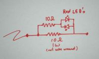
I found that one could make a very effective and simple monitor with two LED's in anti-parallel and two 10 ohm resistors. This seems to be a rather bizarre combination of values which should make the LED's blow from overvoltage and over current but the red LED's haven't blown yet with solid 2 foot sparks from my 4 MOT Tesla coil.
They are quite bright considering that they are only responding to bursts of microsecond pulses that make up a TC streamer ring up, strike and ring down.
Note that you can't run the LED's off DC without putting about 0.4A through the 10 ohm resistor (=4W) and burning it up rapidly.
Pics show
1 circuit diagram,
2 actual low inductance wiring and
3 in use with a Tesla coil. The TC shot actually has them at both ends but the toroid end was mis-wired
 .
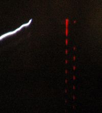
.4 shows a high speed streak camera view of the negative strike and alternating polarity ringdown of sparks (which are not very visible to the camera)
Next post I will show ignition coil sparks and spark arresters.
Peter


Re: LED's for spark monitoring
Steve Conner, Sun Sept 24 2006, 08:15PM
Excellent stuff! I'd never have thought LEDs would survive that kind of abuse either, but 4hv wrote the book on calculated component abuse
Steve Conner, Sun Sept 24 2006, 08:15PM
Excellent stuff!
 I'd never have thought LEDs would survive that kind of abuse either, but 4hv wrote the book on calculated component abuse
Re: LED's for spark monitoring
Tesladownunder, Mon Sept 25 2006, 01:19AM
Well, it gets weirder.
Photo 1 Main resistor 10 ohms, no shunt resistor. Still OK.
Photo 2 No resistors at all You don't need the resistors at all. Well at least for ignition coil stuff.
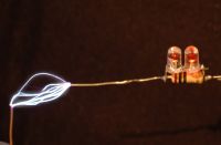
Photo 3 Actually I have known about this for 3 years. Here is my flyback inverter running of a 2N3055 (remember them?) and two antiparallel LED's taking the spark output. These were square non high intensity types but no dropping resistors. The dust confirms how long it has been since I have used them.
I have a recollection of trying this with a TC but they didn't last long but they did for a while. I still haven't blown a red LED so maybe I haven't reached the limit.
Photo 4 I incorrectly wired two LEDs in parallel instead of anti-parallel in the 10 + 10 ohm arrangement with 2 foot TC sparks. Amazingly they didn't blow even though massively overvolted in reverse. The incorrect LED's are at the right and are faint (not aimed well at the camera. I think one of these LED's had reduced output later. Presumably they avalanche very well.
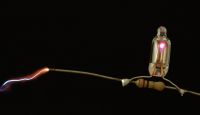
Photo 5 A neon across an 82 ohm resistor just fires. Assuming inductive reactance is not the major factor, and that a neon fires at about 70V this suggests that 10 ohms will have a voltage drop of about 12 volts in this ignition coil setup. It also gives an estimated current of about 800mA peak.
Photo 6 A photoflash Xenon firing across a 1000 ohm resistor. I haven't tested the flash over voltage but perhaps 1000V might be reasonable (although the E fields may trigger it at lower voltages. So similarly about 1 amp seems to be the current.
I now need to test this in a TC circuit and also repeat the readings with the neon /xenon shielded. I will also try smaller resistors which should have a lower inductance to see if inductance is playing a part. I have a few other thoughts as well.
Peter



Tesladownunder, Mon Sept 25 2006, 01:19AM
Well, it gets weirder.
Photo 1 Main resistor 10 ohms, no shunt resistor. Still OK.
Photo 2 No resistors at all
 You don't need the resistors at all. Well at least for ignition coil stuff.
Photo 3 Actually I have known about this for 3 years. Here is my flyback inverter running of a 2N3055 (remember them?) and two antiparallel LED's taking the spark output. These were square non high intensity types but no dropping resistors. The dust confirms how long it has been since I have used them.
I have a recollection of trying this with a TC but they didn't last long but they did for a while. I still haven't blown a red LED so maybe I haven't reached the limit.
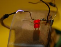
Photo 4 I incorrectly wired two LEDs in parallel instead of anti-parallel in the 10 + 10 ohm arrangement with 2 foot TC sparks. Amazingly they didn't blow even though massively overvolted in reverse. The incorrect LED's are at the right and are faint (not aimed well at the camera. I think one of these LED's had reduced output later. Presumably they avalanche very well.
Photo 5 A neon across an 82 ohm resistor just fires. Assuming inductive reactance is not the major factor, and that a neon fires at about 70V this suggests that 10 ohms will have a voltage drop of about 12 volts in this ignition coil setup. It also gives an estimated current of about 800mA peak.
Photo 6 A photoflash Xenon firing across a 1000 ohm resistor. I haven't tested the flash over voltage but perhaps 1000V might be reasonable (although the E fields may trigger it at lower voltages. So similarly about 1 amp seems to be the current.
I now need to test this in a TC circuit and also repeat the readings with the neon /xenon shielded. I will also try smaller resistors which should have a lower inductance to see if inductance is playing a part. I have a few other thoughts as well.
Peter


Re: LED's for spark monitoring
LarsE, Mon Sept 25 2006, 01:54AM
I tried to put red LED´s on the top load of my small SST and they survived with no problem.
]1159149222_153_FT16359_highvoltageled.wmv[/file]
LarsE, Mon Sept 25 2006, 01:54AM
I tried to put red LED´s on the top load of my small SST and they survived with no problem.
]1159149222_153_FT16359_highvoltageled.wmv[/file]
Re: LED's for spark monitoring
EDY19, Mon Sept 25 2006, 02:15AM
Thats pretty cool LarsE- Not many people have the problem of the leads melting before the LED's die
EDY19, Mon Sept 25 2006, 02:15AM
Thats pretty cool LarsE- Not many people have the problem of the leads melting before the LED's die

Re: LED's for spark monitoring
Nik, Mon Sept 25 2006, 05:55AM
It has to do with current. As long as you dotn run too much current though the LED they really don't seem to care what voltage goes across them. I know this is diffrent but I have run a regular 60w incandecent lightbulb off of a mot (ballasted to ~1000w) and the bulb hapily ran without protest because it was passing the 0.5amps it was rated for. Now what is a little perplexing to me is even though it was running at the correct current it was disipating 1000w insted of 60w, shouldn't that cause the filliment to burn up? Or did I jsut find the least efficint way to light my workspace

Re: LED's for spark monitoring
Marko, Mon Sept 25 2006, 10:44AM
Voltage across something truly IS just a product of it's resistance and current, leds etc. have a constant voltage drop and with few mA they will shine nicely no matter is the current sourced by flyback or 3V battery.
Only care must be taken not to overvolt the LED in reverse with HV.
Your mot bulb didn't 'care' for anything because voltage drop over it's resistnace was probably around it's working voltage adn it shined happily dropping say 200V and dissipating it's 60W. (very poor impedance amtch).
Remaining kolowatt and half remained circling as reactive power being fed back to source.
With TC's it's a bit different: LED's seem to suffer high peak currents but aren't bothered for much, since durations are very short.
Re: LED's for spark monitoring
Tesladownunder, Mon Sept 25 2006, 01:54PM
I have now developed an current meter for HV.
Photo 1 Single unprotected LED, avalanching away happily in reverse.
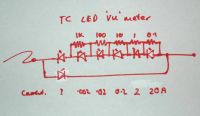
Photo 2 The schematic of the meter showing one reverse LED and 6 forward ones. THe theoretical currents to run the LED's at 2 V are also shown.
Photo 3 The current meter in action.
Photo 4 I have recorded a death of a LED which was a gradual affair with decreasing brightness over minutes of sparks until it stopped. Here it is fading (leftmost LED)
Peter



Tesladownunder, Mon Sept 25 2006, 01:54PM
Firkragg wrote ...
..Only care must be taken not to overvolt the LED in reverse with HV...
Not quite true given the previous video where unprotected single diodes have their leads melted on a TC...Only care must be taken not to overvolt the LED in reverse with HV...
I have now developed an current meter for HV.
Photo 1 Single unprotected LED, avalanching away happily in reverse.
Photo 2 The schematic of the meter showing one reverse LED and 6 forward ones. THe theoretical currents to run the LED's at 2 V are also shown.
Photo 3 The current meter in action.
Photo 4 I have recorded a death of a LED which was a gradual affair with decreasing brightness over minutes of sparks until it stopped. Here it is fading (leftmost LED)
Peter


Re: LED's for spark monitoring
Steve Conner, Mon Sept 25 2006, 02:17PM
Nik, you ballasted it to 1000VA, not 1000W. The resistance of the bulb is so badly matched to what a MOT is designed to drive, that it runs at a very poor power factor.
TDU: Could you connect two of those current meters so one shows negative current and the other positive, and then put them side by side in your streak photos? It should make an oscilloscope-like display, similar to what Terry is trying to do with the LM3914.
Re: LED's for spark monitoring
Tesladownunder, Mon Sept 25 2006, 07:08PM
I also want to be able to short the LED's progressively to avoid exposing the most sensitive ones to high current. I have in mind much higher currents than TC's.
Of course, this still needs to be tested on a TC
It would be good to be able to replace the LED's easily for failures.
I think the metal or carbon film resistors are small enough to have low inductance. Perhaps the 1/4 W ones will have less than the 1W ones. Really I don't know how accurate the divider will be. Still any information is better than none but some calibration would be good.
I could check linearity by putting this setup within a 1000:1 divider and ensuring that it does go down by 3 orders of magnitude. Also should be designed for 1 rather than 2 amps and multiples thereof.
A potential problem is that LED brightness will depend on the time that the current is above the threshhold for that LED. For example the 20A LED still lights dimly, suggesting that the current exceeds 20A for a short time. The first three LED's do seem to be saturated though and there is a drop after that.
It also means that there is no real set endpoint but relative brightness will be easy to see, even without a streak camera. THe streak camera should give really good shots, but the pictures are much dimmer.
Lots to think about but sadly, I have run out of red LED's at the moment and I don't want to pay $2.90 each locally so will have to wait for an eBay order.
Pic shows the reverse polarity LED has died. RIP
Peter

Tesladownunder, Mon Sept 25 2006, 07:08PM
Steve Conner wrote ...
TDU: Could you connect two of those current meters so one shows negative current and the other positive, and then put them side by side in your streak photos? It should make an oscilloscope-like display, similar to what Terry is trying to do with the LM3914.
I want to have positive and negative represented on both ground and toroid ends and I need a wider dynamic range as well with perhaps 8 to 10 orders of magnitude. TDU: Could you connect two of those current meters so one shows negative current and the other positive, and then put them side by side in your streak photos? It should make an oscilloscope-like display, similar to what Terry is trying to do with the LM3914.
I also want to be able to short the LED's progressively to avoid exposing the most sensitive ones to high current. I have in mind much higher currents than TC's.
Of course, this still needs to be tested on a TC

It would be good to be able to replace the LED's easily for failures.
I think the metal or carbon film resistors are small enough to have low inductance. Perhaps the 1/4 W ones will have less than the 1W ones. Really I don't know how accurate the divider will be. Still any information is better than none but some calibration would be good.
I could check linearity by putting this setup within a 1000:1 divider and ensuring that it does go down by 3 orders of magnitude. Also should be designed for 1 rather than 2 amps and multiples thereof.
A potential problem is that LED brightness will depend on the time that the current is above the threshhold for that LED. For example the 20A LED still lights dimly, suggesting that the current exceeds 20A for a short time. The first three LED's do seem to be saturated though and there is a drop after that.
It also means that there is no real set endpoint but relative brightness will be easy to see, even without a streak camera. THe streak camera should give really good shots, but the pictures are much dimmer.
Lots to think about but sadly, I have run out of red LED's at the moment and I don't want to pay $2.90 each locally so will have to wait for an eBay order.
Pic shows the reverse polarity LED has died. RIP
Peter

Re: LED's for spark monitoring
Carbon_Rod, Mon Sept 25 2006, 07:54PM
Tried it a few years back with 5mm clear super-bright RED LEDs. Sometimes if you fry the inside chip in a certain way it will create a rather stable little spark gap sealed inside the plastic (kind of neat for a miniature electrical noise source.)
For RF indicators simply add a LED across a few turns of a coil antenna. (For old cell phones it is about 2 to 3 turns of the GSM antenna IIRC)
Cheers,
Re: LED's for spark monitoring
Terry Fritz, Mon Sept 25 2006, 09:08PM
Hi Peter,
Cool idea!!
I have burnt out LEDs doing this in the past but they "still light"!! In fact, a "burnt out" LED lights fine under high voltage. So it may seem like the LEDs work but if you go to power them up normally they might look dead. However, if the LED still "works" who cares The fancy high brightness and "modern" LEDs often tend to be far more fragile.
I did look at the LM3914 circuit today but the LM3914 starts to pull off at 20kHz and is totally gone at 50kHz. If one wants to do a linear bar graph, it would probably have to be made out of discrete comparators and such. I might still look into that since it would be so cool
Cheers,
Terry
Terry Fritz, Mon Sept 25 2006, 09:08PM
Hi Peter,
Cool idea!!
I have burnt out LEDs doing this in the past but they "still light"!! In fact, a "burnt out" LED lights fine under high voltage. So it may seem like the LEDs work but if you go to power them up normally they might look dead. However, if the LED still "works" who cares
 The fancy high brightness and "modern" LEDs often tend to be far more fragile.
I did look at the LM3914 circuit today but the LM3914 starts to pull off at 20kHz and is totally gone at 50kHz. If one wants to do a linear bar graph, it would probably have to be made out of discrete comparators and such. I might still look into that since it would be so cool

Cheers,
Terry
Re: LED's for spark monitoring
Tesladownunder, Tue Sept 26 2006, 06:22PM
I am in the process of planning a 10 stage bipolar current meter with the bells and whistles.
In this process I tested a red LED and a Blue LED for reverse breakdown. Red forward voltage was 1.5V at 20mA.
........................ Red ..........................Blue
voltage............current uA..................current uA
0 - 9 V..................0............................0
9..........................1...................... ......1
15....................... 2 .......................... 6
21 ...................... 20 ....................... 15
36...................... 100....................... 200
42...................... 280....................... XXXXX (blown)
43..................... 1300....................... XXXXX
So it seems that the red LED acts as a zener with a soft turn on. The blue seemed to blow before any significant current was taken. Hence as determined experimentally, the red LEDs are the best to take HV abuse.
Green LED's went to about 22V before blowing.
Old style red LED's were OK with Zener action at about 23V.
Photo 1 Old style red LED unprotected.
Photo 2 Red LED 3W Lumiled. Reverse protected with standard red LED.
Peter


Re: LED's for spark monitoring
Tesladownunder, Sun Oct 08 2006, 05:36AM
All this is hard on LED's which don't last long. LED's can die by degrees as below. I seem to have blown a lot lately trying to get a current meter going. It goes but eventually the LED's die.
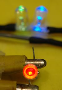
Photo 1 shows a normal red LED driven by 6 VAC via a 1 k resistor plus antiparallel green and blue LEDs which is my wired test setup (very handy). Note the LED die (light emitting square in the centre of the LED. Only the blue LED lights as current only passes in one direction.
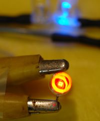
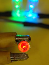
Photo 2 shows a partially dead LED where the square die has a non functioning area. In addition the LED is not bright and it conducts in both directions as both green and blue LED's light up.
Photo 3 shows a partially dead LED where the square die is still normal but the LED is not bright and it also conducts in both directions as both green and blue LED's light up.
Peter


Print this page