
Induction Heater project
mister_rf, Sat Jan 17 2015, 11:34PMI've been reading a lot on the subject and I hope that I’ll have enough time to spend it for, in order to obtain some results until end of this year.

My initial approach is to use the Series Resonant tank via a toroidal coupling transformer.
Similar to other members, that’s a project only for fun, so there are no imposed requirements for now on.
End of the test I hope to achieve up to 3KW (maximum safe power using the standard 230Vac outlet).
For the tank capacitor I use three Inductotherm 670nF capacitors (thank you again Wolfram for the tip about cheap induction heating capacitors on sale).
As a result the working frequencies will be around 70KHz - 100KHz.
I have in plan to start my first experiments using a low voltage and various MOSFET/IGBT's and based on the learning curve to finish this project using two SEMIKRON SKM400GB125D IGBT modules.
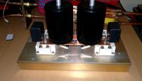
First, I have done mechanical engineering works. Here are some pics.
Gathering all the necessary elements:
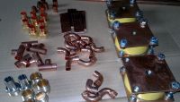
Preparing tank cooling pipes and mounting the caps:
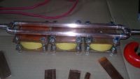
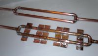
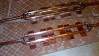
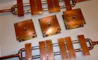
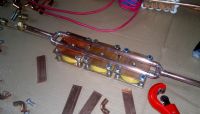
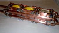
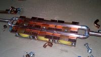
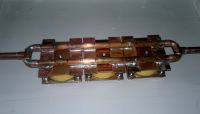
Assembling the coupling transformer (20:1). Mounted the working coil:
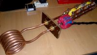
Rectifier/filter caps/IGBT modules:
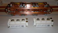
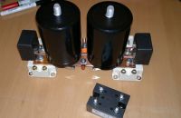
Re: Induction Heater project
loneoceans, Sun Jan 18 2015, 01:33AM
Hey that looks like a fantastic build. Very clean and you can definitely see the amount of work put into it. Looking forward to the build as it progresses :)
loneoceans, Sun Jan 18 2015, 01:33AM
Hey that looks like a fantastic build. Very clean and you can definitely see the amount of work put into it. Looking forward to the build as it progresses :)
Re: Induction Heater project
Wolfram, Sun Jan 18 2015, 12:12PM
Nice and solid build. It should be able to handle 3kW without any problem.
The High Energy Corp engineer I talked with said the caps should be able to handle 650V and at least 600A. I'd limit the cap voltage to 600V RMS for some safety margin. The total capacitance of your bank is 2 µF, so the tank impedance at 100 kHz is 0.8 ohms (and 1.14 ohms at 70 kHz). This means the tank current will be 600 V / 0.8 ohms = 750 A with 600 V across the caps, leading to a total tank reactive power of 450 kVAR.
If you drive the bridge from unsmoothed rectified mains, you'll lose some tank kVAR. The capacitor voltage in this case is a sine modulated by a sine, which has a peak to RMS ratio of 2, but you're still not allowed to exceed the peak voltage of the capacitor even momentarily. The peak voltage the cap is rated to handle is 600 V * sqrt(2) = 850 V, so the maximum RMS voltage you can safely apply in this case is 425 V. With the tank impedance being 0.8 ohms at 100 kHz, you'll get a tank current of 530 A RMS. At 70 kHz (1.14 ohms) you will have a maximum tank current of 370 A RMS, with a max reactive power of 225 kVAR at 100 kHz and 160 kVAR at 70 kHz. With reasonable coupling to the work you should still be able to achieve 3kW of power transfer to your workpiece.
With your 20:1 coupling transformer, primary currents will be maximum 25 A, so I think the 400 A semikron bricks will be a bit overkill. Smaller IGBTs will have lower switching losses than the big bricks, so I would go with some of those instead.
If you go for a higher operating frequency, you should be able to provide more reactive power even with just a single cap. I would guess around 5 kW or more with one cap, running at 200 - 250 kHz. Of course the driver design would be more challenging in this case.
Re: Induction Heater project
mister_rf, Wed Jan 21 2015, 11:40PM
First of all, thank you for your advice and guidance.
Yes, that’s true; I have the same feeling that using the SEMIKRON bricks is far more than is needed for the actual setup.
Anyway, I have in my plan to test various transistors for this experiment, as my personal collection of transistors grew up in time, and maybe later on, those will be used for a final upgrade.
mister_rf, Wed Jan 21 2015, 11:40PM
First of all, thank you for your advice and guidance.
Yes, that’s true; I have the same feeling that using the SEMIKRON bricks is far more than is needed for the actual setup.

Anyway, I have in my plan to test various transistors for this experiment, as my personal collection of transistors grew up in time, and maybe later on, those will be used for a final upgrade.
Re: Induction Heater project
Experimentonomen, Sat Jan 31 2015, 12:51PM
You should flatten the copper pipes alittle to get better thermal and electrical contact with the copper strips mounting to the caps.
Experimentonomen, Sat Jan 31 2015, 12:51PM
You should flatten the copper pipes alittle to get better thermal and electrical contact with the copper strips mounting to the caps.
Re: Induction Heater project
Josh Campbell, Fri Feb 06 2015, 12:18AM
Great job on the initial tank setup, you should have no problem keeping it all cool.
One thing you will notice is that due to the large amount of stray inductance in that type of tank setup, it will heat up any metal (such as a case or parts on a nearby control board) that comes with a few inches when running at moderate power levels. But like you said this is just for fun/learning so you'll probably end up just mounting the thing on a board, which has the added benefit of keeping everything open for easy access.
When you get to the point where your are using your IGBT bricks there is nothing wrong with using good GDT's to drive them. However I would suggest using a hybrid driver not only to give yourself greater flexibility (on-time, dead-time, phasing, etc) but also to protect your investment (good bricks aren't cheap). If you read about series resonant tank setups in induction heating you will find a number of issues involving bridge protection.
Hybrid Driver Example
Re: Induction Heater project
mister_rf, Tue Feb 10 2015, 11:58PM
Thanks for the tips. Over the past few years I have done some research and a lot of reading on this subject and now I have prepared elements for testing hybrid gate drive prototypes. By the way, you're one of the people whose hard work and detailed experiments in this area leads me to start such a project. Thank you again.
For example I have considered to test the HCPL316J gate drive optocoupler, M57962L / VLA542-01R and based on Wolfram’s project, the Silabs SI8234/SI8244 drivers.
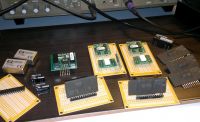
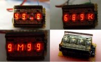
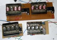
(@Wolfram, I’m still sneak a peek on your experiments, see the cloned auto-range frequency meters prepared for )
)
mister_rf, Tue Feb 10 2015, 11:58PM
Thanks for the tips. Over the past few years I have done some research and a lot of reading on this subject and now I have prepared elements for testing hybrid gate drive prototypes. By the way, you're one of the people whose hard work and detailed experiments in this area leads me to start such a project. Thank you again.
For example I have considered to test the HCPL316J gate drive optocoupler, M57962L / VLA542-01R and based on Wolfram’s project, the Silabs SI8234/SI8244 drivers.

(@Wolfram, I’m still sneak a peek on your experiments, see the cloned auto-range frequency meters prepared for
 )
)

Re: Induction Heater project
Gabriel35, Wed Mar 04 2015, 05:19PM
Hello! Where I can find those capacitors for sale? I need them to build my version of a Induction Heater too...
Thank you!
Gabriel35, Wed Mar 04 2015, 05:19PM
Hello! Where I can find those capacitors for sale? I need them to build my version of a Induction Heater too...
Thank you!
Re: Induction Heater project
mister_rf, Wed Mar 04 2015, 10:24PM
I was lucky.
I have purchased those caps on eBay thanks to the info shared here by Wolfram, see details here:

mister_rf, Wed Mar 04 2015, 10:24PM
I was lucky.

I have purchased those caps on eBay thanks to the info shared here by Wolfram, see details here:

Re: Induction Heater project
Gabriel35, Thu Mar 05 2015, 03:05AM
The listing is ended, what a pitty...
If some of you guys know about any other capacitors like HEC, Inductotherm, Eurofarad or even CELEM at good price and available for sale, please let me know.
And congratulations for the project, i'm looking forward to see the progress, it promises to be very tough IH experiment.
Re: Induction Heater project
Shrad, Thu Mar 05 2015, 01:14PM
have you considered optically triggered switches? I read somewhere that they had pretty switching times...
Shrad, Thu Mar 05 2015, 01:14PM
mister_rf wrote ...
Thanks for the tips. Over the past few years I have done some research and a lot of reading on this subject and now I have prepared elements for testing hybrid gate drive prototypes. By the way, you're one of the people whose hard work and detailed experiments in this area leads me to start such a project. Thank you again.
For example I have considered to test the HCPL316J gate drive optocoupler, M57962L / VLA542-01R and based on Wolfram’s project, the Silabs SI8234/SI8244 drivers.

(@Wolfram, I’m still sneak a peek on your experiments, see the cloned auto-range frequency meters prepared for )
)


Thanks for the tips. Over the past few years I have done some research and a lot of reading on this subject and now I have prepared elements for testing hybrid gate drive prototypes. By the way, you're one of the people whose hard work and detailed experiments in this area leads me to start such a project. Thank you again.
For example I have considered to test the HCPL316J gate drive optocoupler, M57962L / VLA542-01R and based on Wolfram’s project, the Silabs SI8234/SI8244 drivers.

(@Wolfram, I’m still sneak a peek on your experiments, see the cloned auto-range frequency meters prepared for
 )
)

have you considered optically triggered switches? I read somewhere that they had pretty switching times...
Re: Induction Heater project
Wolfram, Thu Mar 05 2015, 02:20PM
Nice frequency counter build. Glad to see that my thread gave you some ideas.
I've found a bug in the rounding code of the frequency counter. It's not very critical, but the problem is that the rounding doesn't work. 39.99kHz will be displayed as 39k9 and not 40k0 as it should.
I fixed it by replacing the following part:
I replaced it with the following:
It's not very refined but it works fine.
I like the silabs drivers because they have simple programmable deadtime, as well as high side UVLO. They are also much faster than many of the alternatives I've seen, and very powerful. The price is also nice.
There are even more alternatives from Infineon and Rohm, and the TI ISO5500, all with desaturation detection.
Wolfram, Thu Mar 05 2015, 02:20PM
Nice frequency counter build. Glad to see that my thread gave you some ideas.
I've found a bug in the rounding code of the frequency counter. It's not very critical, but the problem is that the rounding doesn't work. 39.99kHz will be displayed as 39k9 and not 40k0 as it should.
I fixed it by replacing the following part:
round     MOVLW   digs+D'11'    ; point to first (10MHz) digit
          MOVWF   FSR
roun0     MOVF    0,W           ; search for digit > 0
          BTFSS   STATUS,Z
          GOTO    roun1
          MOVF    FSR,W
          XORLW   digs+4        ; at digit 4
          BTFSC   STATUS,Z
          GOTO    roun1
          DECF    FSR,F
          GOTO    roun0
roun1     MOVLW   3
          GOTO    $+DSPLY       ; skip for DL1414T:
          MOVLW   4
          SUBWF   FSR,F         ; point to last digit - 1
          MOVLW   5             ; add 1/2 last digit
roun2     ADDWF   0,W
          MOVLW   D'10'         ; decimal carry?
          SUBWF   0,W
          BTFSS   STATUS,C
          RETLW   0             ; no: done
          MOVLW   D'10'
          SUBWF   0,F
          MOVLW   1             ; carry
          INCF    FSR,F
          GOTO    roun2
I replaced it with the following:
round     MOVLW   digs+D'11'    ; point to first (10MHz) digit
          MOVWF   FSR
roun0     MOVF    0,W           ; search for digit > 0
          BTFSS   STATUS,Z
          GOTO    roun1
          MOVF    FSR,W
          XORLW   digs+4        ; at digit 4
          BTFSC   STATUS,Z
          GOTO    roun1
          DECF    FSR,F
          GOTO    roun0
roun1     MOVLW   3
          GOTO    $+DSPLY       ; skip for DL1414T:
          MOVLW   4
          SUBWF   FSR,F         ; point to last digit - 1
roun2     MOVF    0,W		;check digit
          INCF    FSR,F
          addlw   .255 - .4	;If digit after last digit is 5 or more
          skpnc
roun3     incf    0,F    	;Increase last digit
          movf    0,W
          addlw   .255 - .9
          skpc
          return
          clrf    0
          incf    FSR,F
          goto    roun3
It's not very refined but it works fine.
I like the silabs drivers because they have simple programmable deadtime, as well as high side UVLO. They are also much faster than many of the alternatives I've seen, and very powerful. The price is also nice.
There are even more alternatives from Infineon and Rohm, and the TI ISO5500, all with desaturation detection.
Re: Induction Heater project
mister_rf, Fri Mar 13 2015, 10:39PM
Thanks for the info, next time I’ll modify the code to improve the displayed frequency accuracy. I had a nice surprise to use some old stuff lying around, and now I see still they are still producing intelligent displays similar to the old ones. So, back to the drawing board….
Anyway, as the typical situation for me, I was stuck in the mechanical details implementation, this time the water cooling unit for the coil.
As related to the drivers, I was curios and I have bought the Silab Eval Board SI823X , and now I’m ready to do some tests.
For this setup I’m prepared to test the C2M0080120D SiC MOSFETs.
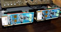
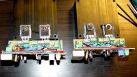
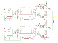
mister_rf, Fri Mar 13 2015, 10:39PM
Thanks for the info, next time I’ll modify the code to improve the displayed frequency accuracy. I had a nice surprise to use some old stuff lying around, and now I see still they are still producing intelligent displays similar to the old ones. So, back to the drawing board….
Anyway, as the typical situation for me, I was stuck in the mechanical details implementation, this time the water cooling unit for the coil.

As related to the drivers, I was curios and I have bought the Silab Eval Board SI823X , and now I’m ready to do some tests.
For this setup I’m prepared to test the C2M0080120D SiC MOSFETs.


Re: Induction Heater project
mister_rf, Tue May 12 2015, 07:37PM
I have decided to split the project and to use dedicated PCB boards for.
Small steps towards the final tests.
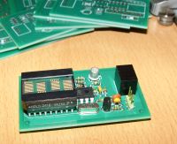
The new PCBs frequency counters ready.
This includes also a JFET buffer option.
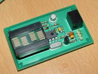
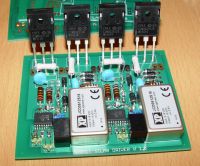
And the PCB MOSFET driver version 1.0 ready for tests.
mister_rf, Tue May 12 2015, 07:37PM
I have decided to split the project and to use dedicated PCB boards for.
Small steps towards the final tests.
The new PCBs frequency counters ready.
This includes also a JFET buffer option.


And the PCB MOSFET driver version 1.0 ready for tests.

Re: Induction Heater project
Wolfram, Wed May 13 2015, 01:34PM
Very nice! It looks like a solid design, and I particularly like the the SiC MOSFETs. I've always wanted to try those myself, and I'm really looking forward to seeing your results with them. The only thing I'd be slightly worried about is the clearance to the ground plane in the bridge board. It's probably fine, but if you're doing a second revision I would recommend increasing the clearance.
With that bridge, you should be able to do many kilowatts at 500 + kHz. You could really make use of those capacitors, which I'm sure can do 1000 A RMS each. One of those caps and a proper work coil, and I would guess you could deliver 10 kW to a workpiece at 300 kHz.
Nice progress, keep us updated.
Re: Induction Heater project
mister_rf, Wed May 13 2015, 07:27PM
Yes, you are right; the actual PCB's clearance is a real problem, so I have decided to use those boards only for testing at low power supply. That was a rookie mistake I have made on leaving the polygon “isolate†option on default (EAGLE Light Edition). I was in a hurry to send those boards to combine shipping with another low voltage project. Anyway, that was cheap mistake, and sooner I will put the new order for the version 4.0.

Re: Induction Heater project
Wolfram, Fri May 15 2015, 04:27PM
Yeah, mistakes are very easy to do, you alredy found some in my design . I sometimes find it useful to use the bRestrict and tRestrict layers to keep ground pours away from critical areas also. You can draw lines, polygons and circles to define the areas where the polygon pour is left out.
I forgot to ask earlier, what are the dimensions of your coupling transformer toroids, and what material are they?
Wolfram, Fri May 15 2015, 04:27PM
mister_rf wrote ...
Yes, you are right; the actual PCB's clearance is a real problem, so I have decided to use those boards only for testing at low power supply. That was a rookie mistake I have made on leaving the polygon “isolate†option on default (EAGLE Light Edition). I was in a hurry to send those boards to combine shipping with another low voltage project. Anyway, that was cheap mistake, and sooner I will put the new order for the version 4.0.
Yes, you are right; the actual PCB's clearance is a real problem, so I have decided to use those boards only for testing at low power supply. That was a rookie mistake I have made on leaving the polygon “isolate†option on default (EAGLE Light Edition). I was in a hurry to send those boards to combine shipping with another low voltage project. Anyway, that was cheap mistake, and sooner I will put the new order for the version 4.0.

Yeah, mistakes are very easy to do, you alredy found some in my design
 . I sometimes find it useful to use the bRestrict and tRestrict layers to keep ground pours away from critical areas also. You can draw lines, polygons and circles to define the areas where the polygon pour is left out.
 I forgot to ask earlier, what are the dimensions of your coupling transformer toroids, and what material are they?
Re: Induction Heater project
mister_rf, Fri May 15 2015, 08:55PM
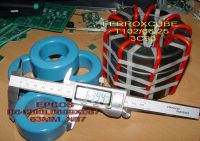
My initial idea was to use the EPCOS B64290L0699X087 63MM, N87 ferrite cores, but recently I have also available for the project some large ferrite toroid made by FERROXCUBE , model T102/66/25-3C90
mister_rf, Fri May 15 2015, 08:55PM
My initial idea was to use the EPCOS B64290L0699X087 63MM, N87 ferrite cores, but recently I have also available for the project some large ferrite toroid made by FERROXCUBE , model T102/66/25-3C90


Re: Induction Heater project
Experimentonomen, Sat May 16 2015, 10:45AM
Big mofos, but not as big as the ones kizmo gotz :P
Experimentonomen, Sat May 16 2015, 10:45AM
Big mofos, but not as big as the ones kizmo gotz :P
Re: Induction Heater project
Wolfram, Mon May 18 2015, 08:24AM
Nice cores. With the setup in your first post with only two of the 63mm cores, you're probably a bit high on the flux density. With two, you have a total core cross section area of 5.35 cm^2 . With 300V peak on the full bridge and 20 primary turns, you have 15 V/turn, and at 70kHz a half period is 7.1 microseconds, so you have about 200 mT peak flux density. At 70l kHz, the core losses will be aroun 30 watts, so they might get a bit toasty. Adding a third core would make it significantly better.
Wolfram, Mon May 18 2015, 08:24AM
mister_rf wrote ...
My initial idea was to use the EPCOS B64290L0699X087 63MM, N87 ferrite cores, but recently I have also available for the project some large ferrite toroid made by FERROXCUBE , model T102/66/25-3C90

My initial idea was to use the EPCOS B64290L0699X087 63MM, N87 ferrite cores, but recently I have also available for the project some large ferrite toroid made by FERROXCUBE , model T102/66/25-3C90


Nice cores. With the setup in your first post with only two of the 63mm cores, you're probably a bit high on the flux density. With two, you have a total core cross section area of 5.35 cm^2 . With 300V peak on the full bridge and 20 primary turns, you have 15 V/turn, and at 70kHz a half period is 7.1 microseconds, so you have about 200 mT peak flux density. At 70l kHz, the core losses will be aroun 30 watts, so they might get a bit toasty. Adding a third core would make it significantly better.
Re: Induction Heater project
mister_rf, Mon May 18 2015, 03:11PM
Thank you for the advice.

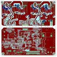
On the other hand, based on the Wolfram’s design, I was temped to squeeze the complete Control Circuit into my 8x10 cm two layers MOSFETs Drive PCB. I have spent some time struggling with the Eagle Light Edition limitations, and finally I have decided it’s time to switch for more functionality and to upgrade. I have attached the four layers PCBs version.
mister_rf, Mon May 18 2015, 03:11PM
Thank you for the advice.

On the other hand, based on the Wolfram’s design, I was temped to squeeze the complete Control Circuit into my 8x10 cm two layers MOSFETs Drive PCB. I have spent some time struggling with the Eagle Light Edition limitations, and finally I have decided it’s time to switch for more functionality and to upgrade. I have attached the four layers PCBs version.

Re: Induction Heater project
Wolfram, Mon May 18 2015, 08:59PM
Nice work. It felt very nice going to four layers, it gives a lot more freedom, especially around the bridge where wide traces are needed for high current. I found out that the board house I use have thinner copper for the inner layers, half the normal thickness, so keep in mind that this will lead to higher than expected I^2 * R losses in the inner layers if you assume they are equal to the outer layers.
Your bootstrap diodes on the HV side of the silabs drivers look very big. I'm a bit worried that such a big diode will have a significant reverse recovery charge so that it will steal some voltage from your bootstrap capacitor when the upper FET/IGBT switches on. This diode only needs to carry the small current to supply the upper gate driver. The main importance is that it needs to handle your DC bus voltage and it needs to be fast.
I feel honored that you've based it on my circuit. Do you have a schematic you can post? Keep in mind that I haven't tested my design completely yet, so I cannot guarantee that everything is 100% correct. My working prototype is a much earlier and simpler version. I'm currently working on putting together some boards that are much closer to the final version, but the last days have been a bit too busy and I haven't tested them yet.
My previous calculation of the flux density was incorrect, the real flux density is only half of what I said earlier, so losses will be much lower and two cores will work fine. This is also great news for my design, as I based my designs on the wrong calculations also. This means that I can get away with much smaller coupling transformers than I expected.
Edit: I don't immediately notice any capacitance across the bridge. I would recommend a few microfarads of polypropylene caps here. With ZCS it is a lot less critical than a hard-switched bridge, but there's still some significant ripple current drawn from the DC bus, which needs to be supplied from somewhere. Having these caps on the board will minimize any voltage drop due to wiring inductance and also the potential for EMI.
Re: Induction Heater project
mister_rf, Tue May 19 2015, 01:53PM
As a matter of fact, I had already considered that aspect. For the bootstrap diodes I have in plan to use some Silicon Carbide Schottky Diode. (C3D02060F/ C3D03060F).
For the future use I have placed some SMDs diode/ resistor pads on the PCBs bottom layer also.
About the schematics, for the moment that’s a little bit too messy. That schematic was compiled in the old software from previous fragments designs, in order to get rid of the 8x10cm size limitation, but to improve the PCBs design, and will take some time so rearrange it.
Anyway, don’t expect too many changes compare to your original design.
And on that PCB I don’t have installed the AC/DC module (including the HALL effect current sensor circuit).
There’s another issue for the moment, and maybe I need to keep to the standard 2 layers PCBs.
The production price for the 4 layers is up too high for my personal demo.
I’ll plan to put in production a small batch of 5 boards, in order to use one piece and later on, to decide if my personal experiments require such upgrade.
Later edit:
and the new 2 layer PCB:
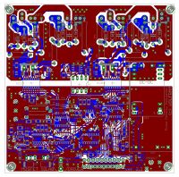
mister_rf, Tue May 19 2015, 01:53PM
As a matter of fact, I had already considered that aspect. For the bootstrap diodes I have in plan to use some Silicon Carbide Schottky Diode. (C3D02060F/ C3D03060F).
For the future use I have placed some SMDs diode/ resistor pads on the PCBs bottom layer also.
About the schematics, for the moment that’s a little bit too messy. That schematic was compiled in the old software from previous fragments designs, in order to get rid of the 8x10cm size limitation, but to improve the PCBs design, and will take some time so rearrange it.
Anyway, don’t expect too many changes compare to your original design.
And on that PCB I don’t have installed the AC/DC module (including the HALL effect current sensor circuit).
There’s another issue for the moment, and maybe I need to keep to the standard 2 layers PCBs.
The production price for the 4 layers is up too high for my personal demo.
I’ll plan to put in production a small batch of 5 boards, in order to use one piece
 and later on, to decide if my personal experiments require such upgrade.
Later edit:
and the new 2 layer PCB:

Re: Induction Heater project
mister_rf, Mon May 25 2015, 12:02AM
A final 3D image of the new PCBs just lunched in production, using a handy online free viewer tool.
You can upload your Gerber files and have a 360 degree view of the PCBs design here:

I manage to squeeze also the small auto ranging 3-digit frequency counter, and just in case I need, for future modifications two ICs spare slots.
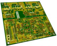
mister_rf, Mon May 25 2015, 12:02AM
A final 3D image of the new PCBs just lunched in production, using a handy online free viewer tool.

You can upload your Gerber files and have a 360 degree view of the PCBs design here:

I manage to squeeze also the small auto ranging 3-digit frequency counter, and just in case I need, for future modifications two ICs spare slots.

Re: Induction Heater project
Wolfram, Wed May 27 2015, 11:01AM
Looks good. I always use that 3D gerber viewer before sending boards to production, it makes it so much easier to see problems in the board design and in the gerber files. Recently I've started using ZofzPCB which has even more options.
I was looking into using SiC devices now, as they are superior to IGBTs in switching characteristics, and there's one thing that worries me a bit. The reverse diode is very fast, but the forward voltage drop is significantly higher than I expected.
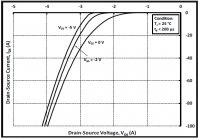
While writing this post I realised that the reverse voltage drop might be lower when the device is on (it's a MOSFET so it conducts in both directions), so it's probably not as bad as it seems, the MOSFETs are always on when the diode is supposed to conduct current. Even in the worst case, this is not catastrophic, but it will lead to some higher losses which could be reduced with an additional parallel diode.
If you already have some SiC MOSFETs, it would be very interesting to check this. If you put some reverse current through the MOSFET with a current limited supply, you can measure the voltage drop across it with Vgs = 0 and Vgs = 15 V . If it's lower with a high gate voltage, there shouldn't be any problems.
Wolfram, Wed May 27 2015, 11:01AM
Looks good. I always use that 3D gerber viewer before sending boards to production, it makes it so much easier to see problems in the board design and in the gerber files. Recently I've started using ZofzPCB
 which has even more options.
I was looking into using SiC devices now, as they are superior to IGBTs in switching characteristics, and there's one thing that worries me a bit. The reverse diode is very fast, but the forward voltage drop is significantly higher than I expected.

While writing this post I realised that the reverse voltage drop might be lower when the device is on (it's a MOSFET so it conducts in both directions), so it's probably not as bad as it seems, the MOSFETs are always on when the diode is supposed to conduct current. Even in the worst case, this is not catastrophic, but it will lead to some higher losses which could be reduced with an additional parallel diode.
If you already have some SiC MOSFETs, it would be very interesting to check this. If you put some reverse current through the MOSFET with a current limited supply, you can measure the voltage drop across it with Vgs = 0 and Vgs = 15 V . If it's lower with a high gate voltage, there shouldn't be any problems.
Re: Induction Heater project
Steve Ward, Mon Jun 08 2015, 07:24AM
Careful with the SiC and no negative gate bias. You will likely incur high switching loss due to dv/dt induced gate turn on of the device that should be off, causing a brief cross conduction. Speaking from experience with that exact SiC FET, and the same gate drivers, i found a -4V bias to be sufficient for inductive switching.
(Sorry for double post, couldn't figure out how to attach a pic with edit.)
Here is how i put a negative bias on my gates with these gate driver ICs (applying nearly the maximum 24V to them). The gate-emitter(source) connects to the 2 pin connectors (G1/G2). The resistors (10K) can be changed to achieve different bias points, for example 10K and 2.2K would be better for SiC as it prefers a high gate voltage and doesn't need too much negative bias.
I've hacked this circuit into boards when I discovered dv/dt induced gate turn on was a problem for my design, especially with fast switching fets.
Re: Induction Heater project
Dr. Slack, Mon Jun 08 2015, 09:07AM
It's a bit of a rigmaroll, but, post the pic in the attachments thread, edit that post to access the link to the picture, copy it, then edit your original post and paste the link in.
Dr. Slack, Mon Jun 08 2015, 09:07AM
Steve Ward wrote ...
(Sorry for double post, couldn't figure out how to attach a pic with edit.)
(Sorry for double post, couldn't figure out how to attach a pic with edit.)
It's a bit of a rigmaroll, but, post the pic in the attachments thread, edit that post to access the link to the picture, copy it, then edit your original post and paste the link in.
Re: Induction Heater project
mister_rf, Mon Jun 08 2015, 10:25PM
@Steve Ward
That was a very good suggestion, thank you for your input. This information is important to the design of optimized gate driver for SiC-MOSFETs, in order to drive SiC MOSFETs in such a way as to facilitate lowest possible conduction and switching losses.
Note to Self: Back to the drawing board. Need to read more information, e.g.
SiC Application Note :SiC Power Devices - Rohm
SiC MOSFET Isolated Gate Driver Application Note - Cree, In
How to fine tune your SiC MOSFET gate driver to minimize
mister_rf, Mon Jun 08 2015, 10:25PM
@Steve Ward
That was a very good suggestion, thank you for your input. This information is important to the design of optimized gate driver for SiC-MOSFETs, in order to drive SiC MOSFETs in such a way as to facilitate lowest possible conduction and switching losses.
Note to Self: Back to the drawing board. Need to read more information, e.g.

SiC Application Note :SiC Power Devices - Rohm
SiC MOSFET Isolated Gate Driver Application Note - Cree, In
How to fine tune your SiC MOSFET gate driver to minimize
Re: Induction Heater project
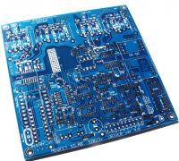
mister_rf, Tue Jun 09 2015, 07:30AM
A new batch has just arrived from the PCB manufacturer for me to test. I need to find a way to use negative gate bias as per Steve Ward’s suggestion.
mister_rf, Tue Jun 09 2015, 07:30AM
A new batch has just arrived from the PCB manufacturer for me to test. I need to find a way to use negative gate bias as per Steve Ward’s suggestion.

Re: Induction Heater project
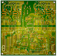
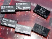
mister_rf, Tue Jun 16 2015, 10:23PM
Up to this moment I didn’t have all the components required in order to start testing, but I have prepared a modified PCB version to include some stand alone DC-DC converters needed to implement the virtual ground. I was considering using -5VDC_DC converters for the SiC MOSFET and -9V/-12V for the standard MOSFETs. The new PCB:


Print this page