Question about impedance matching in high frequency VTTC's
PhilGood, Fri Aug 03 2012, 01:53PMSomeone suggested in my GK-71 HFVTTC Project to add a capacior between anode and ground in order to optimize the coil by matching tube impedance and resonator impedance (if I got it right), basically, something like this :
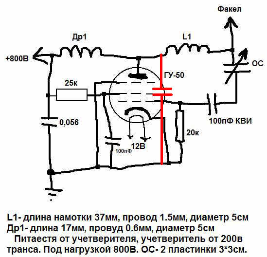
I've been thinking about it, makes sense to me, this would make the resonator circuit look like a pi matching circuit, usually seen in RF transmitters final stage, like this one (random example) :
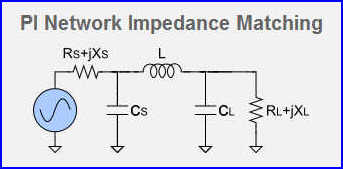
I found an online PI Network Impedance Matching calculator.
Let's suppose in below schematic, Cs is the newly added anode to ground capacitor, L is the resonator, Cl is topload to ground capacitance, and Rl is topload to ground resistance.
I don't know exactly what to input in some fields of the form, I probably need to spend some time to study the theory of this circuit... (clik on pic, it is linked to website) :
What bothers me is that I have never seen such anode to ground capacitor in any power HFVTTC circuit.
I need our Doctors Help !
What you think of this idea. Any comment/explanation would be greatly appreciated

Re: Question about impedance matching in high frequency VTTC's
Dr. Dark Current, Fri Aug 03 2012, 10:41PM
My 30 MHz 1kW plasma flame was tuned just with the 6 pF of plate capacitance of the tube as the actual tank capacitor. The GK-71 will surely have more than 6 pF of plate capacitance, more likely 20 pF, so I think this capacitance alone is enough... Actually it may be more than enough and if you don't draw optimal power out of the resonator to "justifice" the plate capacitance, the efficiency could be lower. In other words, the resonator must have the right impedance to make the plate voltage swing to nearly full supply voltage. In my oscillator I used addtional parallel inductance, which also had a tap to drive the tube and eliminated the capacitive feedback. Actually I calculated this inductance to approximately resonate with the plate capacitance at the resonator frequency...
I'm still not sure if I understand properly what's going on here, and tuning such HF circuits is a kind of "black magic". For example, shortening some wires a few centimeters fixed a problem I was having.
Re: Question about impedance matching in high frequency VTTC's
PhilGood, Sat Aug 04 2012, 04:17AM
Oh I see... I forgot tube capacitance. This makes it all clear, thanks Dr.DC . GK-71 is said to have 10-24pF plate capacitance.
But I don't get exactly how you wired your additional parallel inductance... I have seen some schematics where feedback coil is a few turns in series below resonator, but parallel ? Do you have any schematic you could post ?
Could this have something to do with stationary waves ? I guess wiring reactance and capacitance tend to be critical in a circuit running at 30MHz, wavelenght (around 10 meters) is getting close to our circuit dimensions.
PhilGood, Sat Aug 04 2012, 04:17AM
Oh I see... I forgot tube capacitance. This makes it all clear, thanks Dr.DC
 . GK-71 is said to have 10-24pF plate capacitance.
 But I don't get exactly how you wired your additional parallel inductance... I have seen some schematics where feedback coil is a few turns in series below resonator, but parallel ? Do you have any schematic you could post ?
Dr. Dark Current wrote ...
I'm still not sure if I understand properly what's going on here, and tuning such HF circuits is a kind of "black magic". For example, shortening some wires a few centimeters fixed a problem I was having.
Makes them even more interesting to build ^^ I'm still not sure if I understand properly what's going on here, and tuning such HF circuits is a kind of "black magic". For example, shortening some wires a few centimeters fixed a problem I was having.
Could this have something to do with stationary waves ? I guess wiring reactance and capacitance tend to be critical in a circuit running at 30MHz, wavelenght (around 10 meters) is getting close to our circuit dimensions.
Print this page
