If you need assistance, please send an email to forum at 4hv dot org. To ensure your email is not marked as spam, please include the phrase "4hv help" in the subject line. You can also find assistance via IRC, at irc.shadowworld.net, room #hvcomm.
Support 4hv.org!
Donate:
4hv.org is hosted on a dedicated server. Unfortunately, this server costs and we rely on the help of site members to keep 4hv.org running. Please consider donating. We will place your name on the thanks list and you'll be helping to keep 4hv.org alive and free for everyone. Members whose names appear in red bold have donated recently. Green bold denotes those who have recently donated to keep the server carbon neutral.
Special Thanks To:
Aaron Holmes
Aaron Wheeler
Adam Horden
Alan Scrimgeour
Andre
Andrew Haynes
Anonymous000
asabase
Austin Weil
barney
Barry
Bert Hickman
Bill Kukowski
Blitzorn
Brandon Paradelas
Bruce Bowling
BubeeMike
Byong Park
Cesiumsponge
Chris F.
Chris Hooper
Corey Worthington
Derek Woodroffe
Dalus
Dan Strother
Daniel Davis
Daniel Uhrenholt
datasheetarchive
Dave Billington
Dave Marshall
David F.
Dennis Rogers
drelectrix
Dr. John Gudenas
Dr. Spark
E.TexasTesla
eastvoltresearch
Eirik Taylor
Erik Dyakov
Erlend^SE
Finn Hammer
Firebug24k
GalliumMan
Gary Peterson
George Slade
GhostNull
Gordon Mcknight
Graham Armitage
Grant
GreySoul
Henry H
IamSmooth
In memory of Leo Powning
Jacob Cash
James Howells
James Pawson
Jeff Greenfield
Jeff Thomas
Jesse Frost
Jim Mitchell
jlr134
Joe Mastroianni
John Forcina
John Oberg
John Willcutt
Jon Newcomb
klugesmith
Leslie Wright
Lutz Hoffman
Mads Barnkob
Martin King
Mats Karlsson
Matt Gibson
Matthew Guidry
mbd
Michael D'Angelo
Mikkel
mileswaldron
mister_rf
Neil Foster
Nick de Smith
Nick Soroka
nicklenorp
Nik
Norman Stanley
Patrick Coleman
Paul Brodie
Paul Jordan
Paul Montgomery
Ped
Peter Krogen
Peter Terren
PhilGood
Richard Feldman
Robert Bush
Royce Bailey
Scott Fusare
Scott Newman
smiffy
Stella
Steven Busic
Steve Conner
Steve Jones
Steve Ward
Sulaiman
Thomas Coyle
Thomas A. Wallace
Thomas W
Timo
Torch
Ulf Jonsson
vasil
Vaxian
vladi mazzilli
wastehl
Weston
William Kim
William N.
William Stehl
Wesley Venis
The aforementioned have contributed financially to the continuing triumph of 4hv.org. They are deserving of my most heartfelt thanks.
Registered Member #3323
Joined: Sun Oct 17 2010, 03:19PM
Location: West Midlands, UK
Posts: 116
Hello again everyone,
If you read my first thread a few days ago you will know that I was going to make a railgun, because of recent advice, coilguns are a much better option.
The capacitor bank which I am going to use will be 105 photo-flash capacitors in parallel, overall it will run at 330V, 16800uF, this results in 914.8 Joules.
I am open to different coil sizes, but I was thinking that this wire would be good for the coil, but would like advice...
I have 3 SCRs which are Semikron 339-011-0001. I cannot find any datasheets on these. Also, I have an IGBT, a Toshiba MG100Q2YS42
Depending on the specification on these I might use a mechanical switch, manually 'switched'.
I'm not really sure about the capacitor charging, since I have 105 capacitors, a disposable camera circuit would probably take ages, but of course is an option. I have looked for a while at charging circuits, all I have come up with so far are boost converters, transformers (which appears would have to be custom built by me) and a few other things which I don't see the point of saying...
I understand that I should place a small resistor between each capacitor as protection from inrush current and cascade failure.. But, could I wire the capacitors like this picture but have a resistor between each+ or - terminal. Would it matter which terminal to attach the resistor to?
Does external iron actually make a positive difference to the efficiency or velocity of the projectile?
Using Barry's RLC and Inductor simulator, it looks like worst case scenario ( 330V, 1.00 Ohm, 16.8mF, 10.0mH) would be 205A, ending at 53.2 ms but best case, with 3mm wire, would be ( 330V, 19 milliohms, 16.8mF, 51uH) the coil being 20mm inner, 40mm outer, 87mm long. I guess this avoids fringe effects... This gives 4.72kA and meets the x axis at 2.88ms and gives quite a large reverse current. How would you protect the capacitor bank from at most 2.5kA for 1.5ms?
I think that is it..... and I hope this post hasn't been too boring to read through.
Registered Member #1525
Joined: Mon Jun 09 2008, 12:16AM
Location: America
Posts: 294
You've got a ton of questions, so I'll take a stab at the first few and leave the rest for other contributors:
Navrit Bal wrote ...
I am open to different coil sizes, but I was thinking that this wire would be good for the coil, but would like advice...
Just play with Barry's air-core inductor and RLC simulator until you get something you're happy with. This task is simple after reading Wikipedia's article on series RLC circuits, and is important for you to do/figure out for yourself.
Navrit Bal wrote ...
Depending on the specification on these I might use a mechanical switch, manually 'switched'.
Don't use a mechanical switch. If you are trying to switch 915J you're going to fuse or at worst detonate pretty much whatever mechanical switch you try to use. Also you'll get poor efficiency either way.
Navrit Bal wrote ...
I'm not really sure about the capacitor charging, since I have 105 capacitors, a disposable camera circuit would probably take ages, but of course is an option.
A disposable camera charger is definitely not an option for a bank of your size- you'd be lucky to get it to 100V. A boost converter, IMO, would be perfect for you application. Try Uzzor's design.
Navrit Bal wrote ...
I understand that I should place a small resistor between each capacitor as protection from inrush current and cascade failure..
A parallel resistor is only there for safety reasons- if you accidentally store your gun with a charge, the caps will slowly bleed out into the resistor. If there is a capacitor failure, a parallel R won't stop an explosion or explosive charging from occuring, and the R has to be in series with your bank if you want to limit charging current.
I hope that helps, good luck with your project and keep us posted.
Registered Member #3323
Joined: Sun Oct 17 2010, 03:19PM
Location: West Midlands, UK
Posts: 116
I will read the wikipedia article.
I love how you said 'detonate' there - I definitely won't use a mechanical switch, as I said before I have 3 identical SCRs of unknown value, I recently found that in parallel, SCRs can spread the peak current load across them. Could someone confirm or comment on this?
I might get a custom made power supply from
Fair enough with the resistors, I will keep that in mind when designing the schematic.
Registered Member #1451
Joined: Wed Apr 23 2008, 03:48AM
Location: Boulder, Co
Posts: 661
I've found that with lower power coil guns external iron works great. This is because it will lengthen your pulse (small coilguns usually have fairly fast discharge times) and concentrate the flux in the core of the coil. You could try with or without and see what works best for you.
As for protecting your caps, you should be more worried about your switches. If you use scrs (which you should) the reverse current will completely destroy then first time out. You can prevent this by adding a diode across the coil in anti-parallel (so the cap current doesn't flow through it). This will cut off any reverse voltage at the source. Just make sure the diodes can handle the current. Good guess would to be make them close to the same pulse current rating as your SCRs.
Yes you can put SCRs in parallel and it works great. Add a 100 ohm resistor in series with each gate and tie all the other ends of the resistors together. This will make sure one gate doesn't hog the current and cause only one to turn on or uneven current sharing.
Registered Member #2099
Joined: Wed Apr 29 2009, 12:22AM
Location: Los Altos, California
Posts: 1716
Depending on the specification on these I might use a mechanical switch, manually 'switched'. Don't use a mechanical switch. If you are trying to switch 915J you're going to fuse or at worst detonate pretty much whatever mechanical switch you try to use. Also you'll get poor efficiency either way.
Many experimenters are eager to justify cool, fancy semiconductor switches and (for higher voltages) electrically triggered spark gaps. If you have just one coil, and don't need to control the trigger time exactly, it is hard to beat the efficiency of a mechanical switch. Look at the last project on Barry's site. Mechanical switch should absorb less energy than a semiconductor, because it has less forward voltage. (90% of stored energy will simply heat the coil).
I think my can crusher is pretty efficient as can crushers go -- cuts cans in half with less than 1000 J. Peak current is over 20 kA. The mechanical switch (actually a mechanically triggered spark gap -- the contacts are not allowed to actually touch) has one movable contact that is operated by pulling a lanyard. I think you will find that most successful amateur railguns and coin shrinkers use simple mechanical switches.
Now 330 V is marginally too low to initiate a spark in air, so your switch terminals need to touch. Arrange for them to close rapidly and solidly (e.g. use a rat trap). Coil inductance will limits the current increase during the critical switch bounce period.
Registered Member #3323
Joined: Sun Oct 17 2010, 03:19PM
Location: West Midlands, UK
Posts: 116
I think agree with Klugesmith here on the switching, but wouldn't they weld together, unless they were pretty thick bars of metal? Would this mouse trap be sufficient ?
I'll test external iron when it comes to it. I have had a look for diodes in anti-parallel, but I would still like confirmation of what it actually looks like in a circuit, although I'm pretty sure of what it might look like. Since its unlikely that I will find any cheap diodes that can handle any meaningful current, would it work if I put many diodes in series but in anti-parallel with the rest of the circuit, or many in separate anti-parallel parts? I don't actually know any ratings at all for my SCRs, apart from guessing that they should be able to handle at least 600V and 10's of amps according to who I got them from.
My SCRs look like this but with a H type heatsink, other than that, they look exactly the same, is the big red wire the gate, the white negative and the red positive? I know these questions might sound basic, but I would rather ask than blow stuff up accidentally .
Registered Member #3323
Joined: Sun Oct 17 2010, 03:19PM
Location: West Midlands, UK
Posts: 116
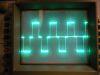
I've just been playing with Barry's RLC simulator, and isn't an effective and preventive measure to reverse polarity current is to add resistance to the circuit and keeping the inductance the same, I am assuming that inductance remains the same, although I know in practice, with the projectile nearby, the inductance does change. Does it go up up or down in these situations and by how much roughly?
Registered Member #2648
Joined: Sun Jan 24 2010, 12:45PM
Location: Australia
Posts: 291
Yep, that is called critical dampening: only problem is that it causes some energy to be lost and makes the pulse longer.
With the stud SCR, look at this: In a stud SCR the Big red lead is normally the Cathode, the stud the anode, the little red lead is the auxiliary Cathode used for triggering and the other thin lead is the gate.
Registered Member #540
Joined: Mon Feb 19 2007, 07:49PM
Location: MIT
Posts: 969
I think that the contacts won't weld as long as you close the gap fast enough (shouldn't be a problem at a low voltage) and that you keep them closed. If the contacts try to open after closing, a large voltage would develop across the gap due to the inductance of the circuit (including the load) trying to keep the current constant. The large voltage would create an arc melting the metal and forming a weld. That's how I've heard it explained but I'm not completely sure.
Registered Member #3323
Joined: Sun Oct 17 2010, 03:19PM
Location: West Midlands, UK
Posts: 116
Myke, your explanation was very good, helpful and makes sense
I think the loss of energy is worth the lack of ringing, and the pulse shape appears to be better. Thanks with the SCR wiring, I was wondering why the stud is used instead of another wire, isn't that a bad safety issue (a big live bit of metal ) ?
This site is powered by e107, which is released under the GNU GPL License. All work on this site, except where otherwise noted, is licensed under a Creative Commons Attribution-ShareAlike 2.5 License. By submitting any information to this site, you agree that anything submitted will be so licensed. Please read our Disclaimer and Policies page for information on your rights and responsibilities regarding this site.


 Coilgun Questions


 ) ?
) ?