If you need assistance, please send an email to forum at 4hv dot org. To ensure your email is not marked as spam, please include the phrase "4hv help" in the subject line. You can also find assistance via IRC, at irc.shadowworld.net, room #hvcomm.
Support 4hv.org!
Donate:
4hv.org is hosted on a dedicated server. Unfortunately, this server costs and we rely on the help of site members to keep 4hv.org running. Please consider donating. We will place your name on the thanks list and you'll be helping to keep 4hv.org alive and free for everyone. Members whose names appear in red bold have donated recently. Green bold denotes those who have recently donated to keep the server carbon neutral.
Special Thanks To:
Aaron Holmes
Aaron Wheeler
Adam Horden
Alan Scrimgeour
Andre
Andrew Haynes
Anonymous000
asabase
Austin Weil
barney
Barry
Bert Hickman
Bill Kukowski
Blitzorn
Brandon Paradelas
Bruce Bowling
BubeeMike
Byong Park
Cesiumsponge
Chris F.
Chris Hooper
Corey Worthington
Derek Woodroffe
Dalus
Dan Strother
Daniel Davis
Daniel Uhrenholt
datasheetarchive
Dave Billington
Dave Marshall
David F.
Dennis Rogers
drelectrix
Dr. John Gudenas
Dr. Spark
E.TexasTesla
eastvoltresearch
Eirik Taylor
Erik Dyakov
Erlend^SE
Finn Hammer
Firebug24k
GalliumMan
Gary Peterson
George Slade
GhostNull
Gordon Mcknight
Graham Armitage
Grant
GreySoul
Henry H
IamSmooth
In memory of Leo Powning
Jacob Cash
James Howells
James Pawson
Jeff Greenfield
Jeff Thomas
Jesse Frost
Jim Mitchell
jlr134
Joe Mastroianni
John Forcina
John Oberg
John Willcutt
Jon Newcomb
klugesmith
Leslie Wright
Lutz Hoffman
Mads Barnkob
Martin King
Mats Karlsson
Matt Gibson
Matthew Guidry
mbd
Michael D'Angelo
Mikkel
mileswaldron
mister_rf
Neil Foster
Nick de Smith
Nick Soroka
nicklenorp
Nik
Norman Stanley
Patrick Coleman
Paul Brodie
Paul Jordan
Paul Montgomery
Ped
Peter Krogen
Peter Terren
PhilGood
Richard Feldman
Robert Bush
Royce Bailey
Scott Fusare
Scott Newman
smiffy
Stella
Steven Busic
Steve Conner
Steve Jones
Steve Ward
Sulaiman
Thomas Coyle
Thomas A. Wallace
Thomas W
Timo
Torch
Ulf Jonsson
vasil
Vaxian
vladi mazzilli
wastehl
Weston
William Kim
William N.
William Stehl
Wesley Venis
The aforementioned have contributed financially to the continuing triumph of 4hv.org. They are deserving of my most heartfelt thanks.
Registered Member #333
Joined: Mon Mar 20 2006, 06:02PM
Location: Czech Republic
Posts: 45
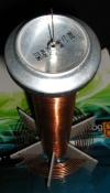
Hello, I was thinking about build a class-E SSTC long time so now this is my first experiment with it. I want to drive my microTC http://rayer.ic.cz/teslatr/microtce.htm where halfbridge is failnig at higher power. I'm unable to make good GDT, even with gate resistors it looks very crappy. Yesterday I built very simple class-E driver with IRFP460. http://rayer.ic.cz/350d/sstce/class-E_SSTC_schematics.gif Coupling capacitor is 150nF/1000V MKS, tankcap - if I understand well should be calculated for f0 and substract the Cds of MOSFET (870pF) so I used 4n7/1250V FKP1. But I'm not sure about RF choke - I see ~50uH is common value so for my 2,25MHz I used something bigger I found 120uH. Gate signal looks quite well, Vds looks like half-wave rectified sinus, I'll add some pics. For firtst light I used variac and 100W bulb current limiter but SSTC impedance i quite low so I didn't get much sparks even on full turned variac. So then I removed bulb and it started sparking at ~10V. I got up to 5cm hot sparks from this micro TC, nice but everything goes hot soon (even at halfwave, no filter) - it would need some interrupter. I know heatsink is not so big http://rayer.ic.cz/350d/sstce/IMG_1161s.jpg I'll try mount a fan.
EDIT: I forgot to mention that of course I finally popped the MOSFET when wanting more sparks :) Fortunatelly gatedriver survived. I also found that it can be driven at f0/2 where it takes near 1/2 of current compared to f0 drive but sparks are only slightly shorter.
Registered Member #1232
Joined: Wed Jan 16 2008, 10:53PM
Location: Doon tha Toon!
Posts: 881
The RF choke in a Class-E amplifier acts as an approximate constant current source to the switch and resonant load network. Or, to put it another way the RF choke smooths out the supply current that would otherwise be heavily pulsating as the single transistor switches on and off.
As for the value, it is usually chosen to limit the peak-to-peak current ripple in the supply wiring to some fraction of the overall DC current consumption. For instance a 600W Class-E amplifier running off 150V will draw 4A DC, so you might choose the RFC to limit current ripple to +/- 100mA. Typical ripple values are between 5 and 10% of the average DC current consumption.
At first it might seem that more is better for the RF choke as it minimuses the supply current ripple as far as possible, ...but as with all things in engineering there are tradeoffs here. An RFC that is too large will cause the following to occur:
1. High copper losses due to lots of turns on the iron-powder core.
2. Subject the core to more amp-turns from the DC component of the supply current and hence saturate the core more reducing it's affectiveness at filtering out the AC ripple.
In addition to this a large RF choke inductance can smooth the load current _too_ much. In short the more inductance you have the more it acts to keep the supply current constant. This can be a big problem if you intend to amplitude modulate the supply voltage to the amplifier for either an AM radio transmitter, or for an audio modulated TC. The larger the RF choke the longer the Class-E amplifier takes for it's current consumption to respond to changes in supply voltage. This lag causes lowpass filtering of the modulation envelope with a cutoff frequency that becomes lower and lower as the RFC inductance increases.
Under some circumstances an RFC that is too large can also cause squegging to take place in MOSFET Class-C and Class-E power amps. This is where the non-linear reverse transfer capacitance of the MOSFET can cause the operating point of the amplifier to become unstable. The supply current oscillates wildly at some arbitrary frequency well below the normal intended operating frequency. You can easily see if this occurs on an oscilloscope as the RF appears to be modulated by a dirty periodic waveform that is usually somewhere between the high kHz to low 100's of kHz. In an RF transmitter such squegging causes broadband emission outside of the allocated part of the spectrum!
For these reasons I specify an RF choke that is of the smallest value that can adequately supress the AC component of the supply current. Anything more than this compromises modulation bandwidth, risks instability and is more lossy & bulky than necessary.
-Richie,
PS. Also don't use Type-26 iron powder. It is a really lousy material intended for use at low frequencies in cheap SMPSUs. Type-6 or particularly Type-2 from Micrometals are ideal choices for RF chokes in HF Class-E power amps.
Registered Member #333
Joined: Mon Mar 20 2006, 06:02PM
Location: Czech Republic
Posts: 45
Thanks for reply. Well so this value is not critical, nothing to be specially tuned.
And how do I calculate the DC current draw? I think, if well tuned there will left only the resistive component of the load which should be R = Q*Xl = Q*Xc @f0 = 2,24MHz for parallel resonant circuit, in my case Xl ~= 13ohm, runtime Q guess 10 with spark load so R ~= 130ohm. and it should draw I ~= 30V / 130ohm = 0.23A DC. But I measured it draws about 2,5A DC at 30V DC so load impedance seems to be only 12ohm...
Anyway, if I calculate with ripple 5% it's 0,125App (0.03Aef) => Xlc = 960ohm => Lc = 68uH. I should use smaller inductance. Yes curently I use iron powder choke from PSU (yellow core) I know it's lossy but I quickly didn't found better. I have some toroidal cores so I can winding it but I guess ferrite may have problem with saturation.
Yesterday I built simple interrupter with 555 and 7402 and now it heats less, one photo here
Registered Member #333
Joined: Mon Mar 20 2006, 06:02PM
Location: Czech Republic
Posts: 45
william L wrote ...
Nice coil! why not put a weak 555 signal to keep the oscillations going?
Currently I don't care about frequency source - I just use my TTL frequency generator for testing. But in final version I'll probably use 74HC4046 PLL as on my DRSSTC. Maybe just 74HC14 inverter would be enough when using interrupter which triggers VF oscillations...
Registered Member #333
Joined: Mon Mar 20 2006, 06:02PM
Location: Czech Republic
Posts: 45
Damn, I screwed my microTC secondary. Varnish cracked by heat and when removing it I messed the winding. Such thin wire is pure EVIL, no more! I'm going to make new one, using 0.125mm wire and make it little bit longer so f0 wouldn't rise too much. Hope this will work better... :\
EDIT: I made new secondary with 0.125mm wire. It was much much easier to wound it thand damned 0.06. But it resonate very high, about 4,7MHz with mini toroid. I did first light with limited powe and got 35mm sparks at 35VDC. I'll go further after replacing slow IRFP460 by faster STW20NM50...
Registered Member #333
Joined: Mon Mar 20 2006, 06:02PM
Location: Czech Republic
Posts: 45
So I decided to replace IRFP460 with very large Cg by modern STW20NM50 but I burned both during first testing and I don't know how. I watched Ugs and it looks quite good, max 12V, total gate driver power 3,8W. Drain circuit was powered from another 12V supply 78S12 with 2200uF filter. Uds surely did not exceed 100V. This supply gave max. 2,4A until thermal fuse limitation. So I damaged the MOSFET with only ~20W RMS power (it has Pd 190W), strange. Heatsink was warm but I still can hold hand on it. Also weird that it was only half-shorted (Rgs ~1k, Rds ~1ohm) I always saw 0ohm between all electrodes.
I also observed another problem. When I put only a resistor to drain instead TC I can see that FET is on most of time. It mean that DC current is quite high. I think it's due to asymetric tdon/tdoff times, 20ns vs 90ns, while half-period is about 115ns. My Idea is that I need duty cycle compensation fed from generator, say 20-30% instead of 50%. This should equalize timing on drain side and lower the DC current draw. What do you think?
This site is powered by e107, which is released under the GNU GPL License. All work on this site, except where otherwise noted, is licensed under a Creative Commons Attribution-ShareAlike 2.5 License. By submitting any information to this site, you agree that anything submitted will be so licensed. Please read our Disclaimer and Policies page for information on your rights and responsibilities regarding this site.


 RF choke value for class-E SSTC?


