If you need assistance, please send an email to forum at 4hv dot org. To ensure your email is not marked as spam, please include the phrase "4hv help" in the subject line. You can also find assistance via IRC, at irc.shadowworld.net, room #hvcomm.
Support 4hv.org!
Donate:
4hv.org is hosted on a dedicated server. Unfortunately, this server costs and we rely on the help of site members to keep 4hv.org running. Please consider donating. We will place your name on the thanks list and you'll be helping to keep 4hv.org alive and free for everyone. Members whose names appear in red bold have donated recently. Green bold denotes those who have recently donated to keep the server carbon neutral.
Special Thanks To:
Aaron Holmes
Aaron Wheeler
Adam Horden
Alan Scrimgeour
Andre
Andrew Haynes
Anonymous000
asabase
Austin Weil
barney
Barry
Bert Hickman
Bill Kukowski
Blitzorn
Brandon Paradelas
Bruce Bowling
BubeeMike
Byong Park
Cesiumsponge
Chris F.
Chris Hooper
Corey Worthington
Derek Woodroffe
Dalus
Dan Strother
Daniel Davis
Daniel Uhrenholt
datasheetarchive
Dave Billington
Dave Marshall
David F.
Dennis Rogers
drelectrix
Dr. John Gudenas
Dr. Spark
E.TexasTesla
eastvoltresearch
Eirik Taylor
Erik Dyakov
Erlend^SE
Finn Hammer
Firebug24k
GalliumMan
Gary Peterson
George Slade
GhostNull
Gordon Mcknight
Graham Armitage
Grant
GreySoul
Henry H
IamSmooth
In memory of Leo Powning
Jacob Cash
James Howells
James Pawson
Jeff Greenfield
Jeff Thomas
Jesse Frost
Jim Mitchell
jlr134
Joe Mastroianni
John Forcina
John Oberg
John Willcutt
Jon Newcomb
klugesmith
Leslie Wright
Lutz Hoffman
Mads Barnkob
Martin King
Mats Karlsson
Matt Gibson
Matthew Guidry
mbd
Michael D'Angelo
Mikkel
mileswaldron
mister_rf
Neil Foster
Nick de Smith
Nick Soroka
nicklenorp
Nik
Norman Stanley
Patrick Coleman
Paul Brodie
Paul Jordan
Paul Montgomery
Ped
Peter Krogen
Peter Terren
PhilGood
Richard Feldman
Robert Bush
Royce Bailey
Scott Fusare
Scott Newman
smiffy
Stella
Steven Busic
Steve Conner
Steve Jones
Steve Ward
Sulaiman
Thomas Coyle
Thomas A. Wallace
Thomas W
Timo
Torch
Ulf Jonsson
vasil
Vaxian
vladi mazzilli
wastehl
Weston
William Kim
William N.
William Stehl
Wesley Venis
The aforementioned have contributed financially to the continuing triumph of 4hv.org. They are deserving of my most heartfelt thanks.
Registered Member #543
Joined: Tue Feb 20 2007, 04:26PM
Location: UK
Posts: 4992
Grenadier wrote ...
I followed this guide:
After taking apart the tubehead, it turns out that the HV punched right through the tube. This was one of my initial concerns, because of the conductive lead shielding and the thin glass. I compensated for this by putting oil between the lead and the tube, but when the heater cut out the oil stood no chance against the increased voltage.
I'm not really crying though. This tube wasn't the best of quality anyway and judging by the burn mark on the anode, its focal spot was 1.5mm (though it was *supposed* to be only .7mm).
This CEI tube I'm going to use is bigger, has thicker glass and a .5mm focal spot. It's an all around better tube, and should provide all around better images.
When I rebuild it I'm also going to make sure that the HV cuts out if the heater does. Should have done that in the first place...
Also going to insulate the tube from the lead better.
Still, it's always a shame to lose expensive parts.
I'd suggest having a minimum of 25mm between the glass envelope and the shielding
(a) to assist convection cooling of the glass by the dielectric oil
(b) to keep down the capacitance between the internal electrodes and the shielding, which alone could provoke a glass strike.
No doubt someone will step in and say such a wide spacing is unnecessary, but then they won't be the ones paying the replacement cost, and waiting who knows how long for new parts to arrive in the post.
I suggest as minimum HV lock-out features:
(1) Heater must have been running for 5 minutes before HV can be applied.
(2) HV will auto-disconnect in the event of heater current falling below I mA
(3) HV will auto-disconnect if an attempt is made to open the case during operation - as per microwave oven.
On focal spots: the area of anode erosion will always be larger than the focal spot itself, because heat travels outward from the impacted zone. The standard way to measure the focal spot size uses simple geometry based on careful pin-hole imaging - a skill well worth the trouble of learning how to do well.
The focal spot size, definition, and symmetry will deteriorate over time as the impacted zone starts to pit and crack.
You should also ask yourself how much your focal spot may be deflected, modified, or enlarged by unstable off-axis electric fields inside the casing.
Registered Member #2893
Joined: Tue Jun 01 2010, 09:25PM
Location: Cali-forn. i. a.
Posts: 2242
I don't have enough room for such spacing in there. From all the X-ray heads I've taken apart though, the tube jacket is never more than 1cm away from the tube, and often it's <5mm.
I have a few tubes to choose from. One is the CEI-OCX-70G, another tube is the TRX-708 from kodak. Both tubes have their anodes embedded in the copper block to block off axis radiation. The TRX-708 has a nicer anode hole (and would make a rounder beam) than the CEI one, but the focal spot seems to be a line rather than a spot.
The OCX-70G has a control grid, but I don't need it so I'm likely just going to leave it disconnected if I use that tube. I also have an OCX-65G, but that one isn't new while my 70G is.
I also have another tube, one that is clearly used but has a perfect anode. No markings on it however.
I have a tube shield too, Two actually. One of them has a lead sheath with a ceramic "inside part (insulator maybe)", while the other is the same but with a phenolic tube insulator. I plan on using one of those instead of a handmade shield.
Registered Member #543
Joined: Tue Feb 20 2007, 04:26PM
Location: UK
Posts: 4992
Grenadier wrote ...
I don't have enough room for such spacing in there. From all the X-ray heads I've taken apart though, the tube jacket is never more than 1cm away from the tube, and often it's <5mm.
But they didn't use your chaotic power supply, did they?
And if they were dental or fixed anode medical radiography heads, how long would a typical exposure be? A few hundred milliseconds? less? - you will have to think about cooling in general - and the datasheet figure for the heat capacity of the anode in particular - if your tube is to survive many seconds of continuous use in your video experiments.
Registered Member #2893
Joined: Tue Jun 01 2010, 09:25PM
Location: Cali-forn. i. a.
Posts: 2242
True, but my power supply isn't supposed to be chaotic. My mistake was not putting in the HV kill when the power to the heater was inadvertently cut.
I think I'm going to use the 70G for this. I fit it inside the phenolic tube insulated shield with some hose and soon a small dab of epoxy. This tube has the anode "arm" recessed a bit inside the glass, so I am going to slide a platic tube in there to prevent sparking to the shield in case of failure.
The tube has a .7mm focal spot and a 10kJ heat storage capacity. Sure tubes in commercial sets don't run long, but they are running at 500+ watts while I'll run mine at no more than 130W.
So now I just need to wait for a new EL wire inverter and then I can put this back together. I'm going to order a huge amount of 5.1V zener diodes, 18V zeners and 40V zeners to protect all the power rails. I'll also add some 3.1V zeners across the heater to protect the buck converter there.
Oddly enough, that buck converter is the only thing I haven't been able to blow up, and I expected it to be the most fragile thing. It's right next to the HV both physically and electrically... Idunno.
Only thing that I can't do anything about really, if the buck converter there fails then the tube will have no heater. I can clamp the voltage at 5.5V (to protect the heater) until a fuse on the heater blows, but that's about it.
Hrm... now that I think about it, I might be able to do some clever rewiring that kills both the HV and the heater if that fuse + buck blows. Well maybe not... both use different currents. Ah, but I can ground the ZVS relay *after* the fuse. That will kill both if something goes wrong
Registered Member #3429
Joined: Sun Nov 21 2010, 02:04AM
Location: Minnesota, USA
Posts: 288
Grenadier wrote ...
I'm not really crying though. This tube wasn't the best of quality anyway and judging by the burn mark on the anode, its focal spot was 1.5mm (though it was *supposed* to be only .7mm).
The actual focal spot size that you see on the target of an X-ray tube is not the nominal focal spot that you read in the data sheet for that specific tube. The data sheet refers to the "effective" focal spot size, which is the focal spot that the imaging film or digital sensor "sees", due to the angle of the target. Most dental and medical X-ray tubes use the "line focus principle" technique where the filament is typically much longer than it is wide, and therefore produces an etch or burn mark on the Tungsten target which is long and thin (in your case it is 1.5mm long). Here's a good way to visualize how the line focus principle works. Imagine a 12-inch ruler floating vertically about a couple of feet in front of your face, with the center exactly in line with your eyes. The ruler of course looks to be 12 inches long. Now imagine that someone rotates the ruler so that the upper 6 inches now slopes away from your face, and the lower 6 inches slopes toward your face, and they rotated it exactly 45 degrees from its initial position. Now, the ruler no longer appears to be 12 inches long to your eyes! It will appear to be 12 * sin(45) = 8.49 inches long! So, the actual length is still 12 inches, but the effective length is much shorter. That's the basics of how line focus works with X-ray tubes. Depending on the focal spot length to width ratio, and the angle of the anode (target), the effective focal spot might appear to be a tiny square dot, even though the filament is long and skinny!
Registered Member #2893
Joined: Tue Jun 01 2010, 09:25PM
Location: Cali-forn. i. a.
Posts: 2242
I see that, but looking directly into the anode hole of that tube you could see that the burn mark was taller than it was wider, and it was a line, even from that POV. I think that tube might just be messed up or something.
Registered Member #543
Joined: Tue Feb 20 2007, 04:26PM
Location: UK
Posts: 4992
Grenadier wrote ...
True, but my power supply isn't supposed to be chaotic. My mistake was not putting in the HV kill when the power to the heater was inadvertently cut.
I think I'm going to use the 70G for this. I fit it inside the phenolic tube insulated shield with some hose and soon a small dab of epoxy. This tube has the anode "arm" recessed a bit inside the glass, so I am going to slide a platic tube in there to prevent sparking to the shield in case of failure.
The tube has a .7mm focal spot and a 10kJ heat storage capacity. Sure tubes in commercial sets don't run long, but they are running at 500+ watts while I'll run mine at no more than 130W.
So now I just need to wait for a new EL wire inverter and then I can put this back together. I'm going to order a huge amount of 5.1V zener diodes, 18V zeners and 40V zeners to protect all the power rails. I'll also add some 3.1V zeners across the heater to protect the buck converter there.
Oddly enough, that buck converter is the only thing I haven't been able to blow up, and I expected it to be the most fragile thing. It's right next to the HV both physically and electrically... Idunno.
Only thing that I can't do anything about really, if the buck converter there fails then the tube will have no heater. I can clamp the voltage at 5.5V (to protect the heater) until a fuse on the heater blows, but that's about it.
Hrm... now that I think about it, I might be able to do some clever rewiring that kills both the HV and the heater if that fuse + buck blows. Well maybe not... both use different currents. Ah, but I can ground the ZVS relay *after* the fuse. That will kill both if something goes wrong
You're doing very well. Your persistence with this project over many months does you credit!
I'm pleased that friend "X-ray" has popped up to advise you, because I have very little practical experience with medical tubes and their particular HV needs to share with you. The world looks very different below 5 keV, where I have staked my claim.
Registered Member #2893
Joined: Tue Jun 01 2010, 09:25PM
Location: Cali-forn. i. a.
Posts: 2242
Heh, yeah too bad things keep exploding. >_<
After this is done I want to make a second head for this machine, one with a low energy x-ray tube. This head is [was] only capable of energies down to about 40keV, so I'd need a second head to take images of soft things like flowers. Unfortunately all of my tubes are thick glass, and are thus incapable of making decent quantities of low energy x-rays.
I've had no luck finding a beryllium or aluminum window x-ray tube anywhere
Registered Member #3429
Joined: Sun Nov 21 2010, 02:04AM
Location: Minnesota, USA
Posts: 288
Grenadier wrote ...
Unfortunately all of my tubes are thick glass, and are thus incapable of making decent quantities of low energy x-rays.
I've had no luck finding a beryllium or aluminum window x-ray tube anywhere
All X-ray tubeheads used for X-raying living tissue have metallic (usually aluminum) filters directly in the path of the raw beam as it exits the tubehead. The filters attenuate the lower portion of the energy spectrum, which is too weak to produce a useful image, but can burn the skin. Because you will not be X-raying living tissue, you do not need filtration, and if you can reduce the amount of oil that's between the glass X-ray tube and the exit window, you should be able to get decent low-energy photons from it.
I have a couple of very small tubes (about the size of a large walnut) that have a portion of the thick glass ground down to a thin glass window. The thin glass may not be as transparent to X-rays as beryllium is, but it should work just fine for X-raying flowers and seashells, etc. Let me know if you want one of them and maybe we can work out a trade.
This site is powered by e107, which is released under the GNU GPL License. All work on this site, except where otherwise noted, is licensed under a Creative Commons Attribution-ShareAlike 2.5 License. By submitting any information to this site, you agree that anything submitted will be so licensed. Please read our Disclaimer and Policies page for information on your rights and responsibilities regarding this site.


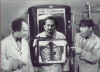
 Grenadier's big thread of Röntgen related shenanigans