 3x 18mF @ 350V -> What to do? 3x 18mF @ 350V -> What to do?
|
|
|
DerAlbi
|
|
Wed Sept 28 2011, 04:02AM
|
|
|
 Registered Member #2906
Joined: Sun Jun 06 2010, 02:20AM
Location: Dresden, Germany
Posts: 727
|
I worked hard the last week(s). I had a change of concept for this IGBT module.
1) The IGBTs were killed by overvoltage. You can see this by looking at the gate-bond-wire closely. Overvoltage means:
a) Too high Emitter-Collector-voltage >> 800V: I added 440V supressor diode at !every! IGBT between E-C.
b) Too high Gate-Emitter-voltage >> 30V: I added a 18V supressor diode at every gate between G-E
c) Reverse voltage >> unspecified negative voltage: I was told that IGBTs usually react badly negative voltages larger than (or in range of) the maximum E-G-voltage): The 440V supressor diodes are unidirectional -> negative voltage is clamped to -0.6V at every IGBT.
2) The IGBTs can be killed by overcurrent / bad balancing
a) I added 20mOhm at every Collector: hoping this gives better balancing performance than the resistor-tree before.. There are 16 IGBTs in parallel... 20mOhm/16.. is an acceptable loss;-)
b) I added 20mOhm at every Emitter: I have built a simulation model of the IGBTs to match its specified transfer-characteristics. With this simulation i determined i need 20mOhm with 15V at the gates to limit the current to 320A through every IGBTs.
3) Reducing the amount of diodes:
The diodes i use are specified for 400A for 8.3ms. I used 18pcs in parallel. They can handle upto 9kA.. This is useless. I do not need this kind of current.
The diodes seem to be quite slow. They are only rectifier diodes. The reverse recovery time issnt even specified. In this time however the negative E-C-potential could build up. I reduced the amount of diodes in parallel to 10. This limits the current stress of the unidirectional supressor diodes (1c).
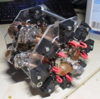
4) New design reduced parasitic inductance - this reduces voltage spikes.
a) The Emitter and Collector resistors are directly parallel and in close proximity together. This minimizes the area between them.
b) The resistors are fold kind of bifilar to reduce area.
c) IGBTs are arranged in a star configuration, Lets hope this geometry helps to cancle out some magnetic parasitic effects.
Here it is:

5) I have improved the gate driver for the HighSide.
I measured bad timing issues at the four gate drivers they switch not perfectly parallel. When turning of the IGBTs this could have caused a single block of IGBTs to take all the current. So 4 IGBTs would do the work of 16 for a short time.
The synchronicity is now improved to 20ns difference max.
I will now work at the wireing. All gates now need to be connected. i wonder if this is critical to overvoltage due to possible induction into te koax-cable.
I have no idea.
Btw: Has anyone an idea about GhostNull? Touched some wires or...?
|
|
Back to top
|
|
Moderator(s): Chris Russell, Noelle, Alex, Tesladownunder, Dave Marshall, Dave Billington, Bjørn, Steve Conner, Wolfram, Kizmo, Mads Barnkob
|
|
Powered by e107 Forum System
|

