If you need assistance, please send an email to forum at 4hv dot org. To ensure your email is not marked as spam, please include the phrase "4hv help" in the subject line. You can also find assistance via IRC, at irc.shadowworld.net, room #hvcomm.
Support 4hv.org!
Donate:
4hv.org is hosted on a dedicated server. Unfortunately, this server costs and we rely on the help of site members to keep 4hv.org running. Please consider donating. We will place your name on the thanks list and you'll be helping to keep 4hv.org alive and free for everyone. Members whose names appear in red bold have donated recently. Green bold denotes those who have recently donated to keep the server carbon neutral.
Special Thanks To:
Aaron Holmes
Aaron Wheeler
Adam Horden
Alan Scrimgeour
Andre
Andrew Haynes
Anonymous000
asabase
Austin Weil
barney
Barry
Bert Hickman
Bill Kukowski
Blitzorn
Brandon Paradelas
Bruce Bowling
BubeeMike
Byong Park
Cesiumsponge
Chris F.
Chris Hooper
Corey Worthington
Derek Woodroffe
Dalus
Dan Strother
Daniel Davis
Daniel Uhrenholt
datasheetarchive
Dave Billington
Dave Marshall
David F.
Dennis Rogers
drelectrix
Dr. John Gudenas
Dr. Spark
E.TexasTesla
eastvoltresearch
Eirik Taylor
Erik Dyakov
Erlend^SE
Finn Hammer
Firebug24k
GalliumMan
Gary Peterson
George Slade
GhostNull
Gordon Mcknight
Graham Armitage
Grant
GreySoul
Henry H
IamSmooth
In memory of Leo Powning
Jacob Cash
James Howells
James Pawson
Jeff Greenfield
Jeff Thomas
Jesse Frost
Jim Mitchell
jlr134
Joe Mastroianni
John Forcina
John Oberg
John Willcutt
Jon Newcomb
klugesmith
Leslie Wright
Lutz Hoffman
Mads Barnkob
Martin King
Mats Karlsson
Matt Gibson
Matthew Guidry
mbd
Michael D'Angelo
Mikkel
mileswaldron
mister_rf
Neil Foster
Nick de Smith
Nick Soroka
nicklenorp
Nik
Norman Stanley
Patrick Coleman
Paul Brodie
Paul Jordan
Paul Montgomery
Ped
Peter Krogen
Peter Terren
PhilGood
Richard Feldman
Robert Bush
Royce Bailey
Scott Fusare
Scott Newman
smiffy
Stella
Steven Busic
Steve Conner
Steve Jones
Steve Ward
Sulaiman
Thomas Coyle
Thomas A. Wallace
Thomas W
Timo
Torch
Ulf Jonsson
vasil
Vaxian
vladi mazzilli
wastehl
Weston
William Kim
William N.
William Stehl
Wesley Venis
The aforementioned have contributed financially to the continuing triumph of 4hv.org. They are deserving of my most heartfelt thanks.
Registered Member #91
Joined: Thu Feb 09 2006, 03:03PM
Location: The Netherlands
Posts: 45
I've been working on an improved version of my SSTC for quite some time and today it was finally time to power it up for the first time.
My previous SSTC was almost entirely based on Steve Ward's mini SSTC. It worked, but not especially well and the MOSFETs exploded on a regular basis. So for this new coil I ditched everything but the secondary coil and started again from scratch.
The first thing I made was a remote control box which also contains an interrupter. The interrupter is a simple 555 design. The on- and off-times can be controlled by using two potentiometers. There is also a knob to select one of six possible interrupter modes, each resulting in its own particular spark appearance. The box connects to the SSTC controller through a shielded 8-core data cable (of which only 4 wires are used, but I could get the shielded 9-pin D-SUB connectors for much less than shielded 4-pin connectors...). There is also room reserved for an audio interrupter, but I haven't made one yet. The small "on/off" switch doesn't have a function yet.
Then it's on to the power electronics. I made a wooden base on which everyting is mounted in place.
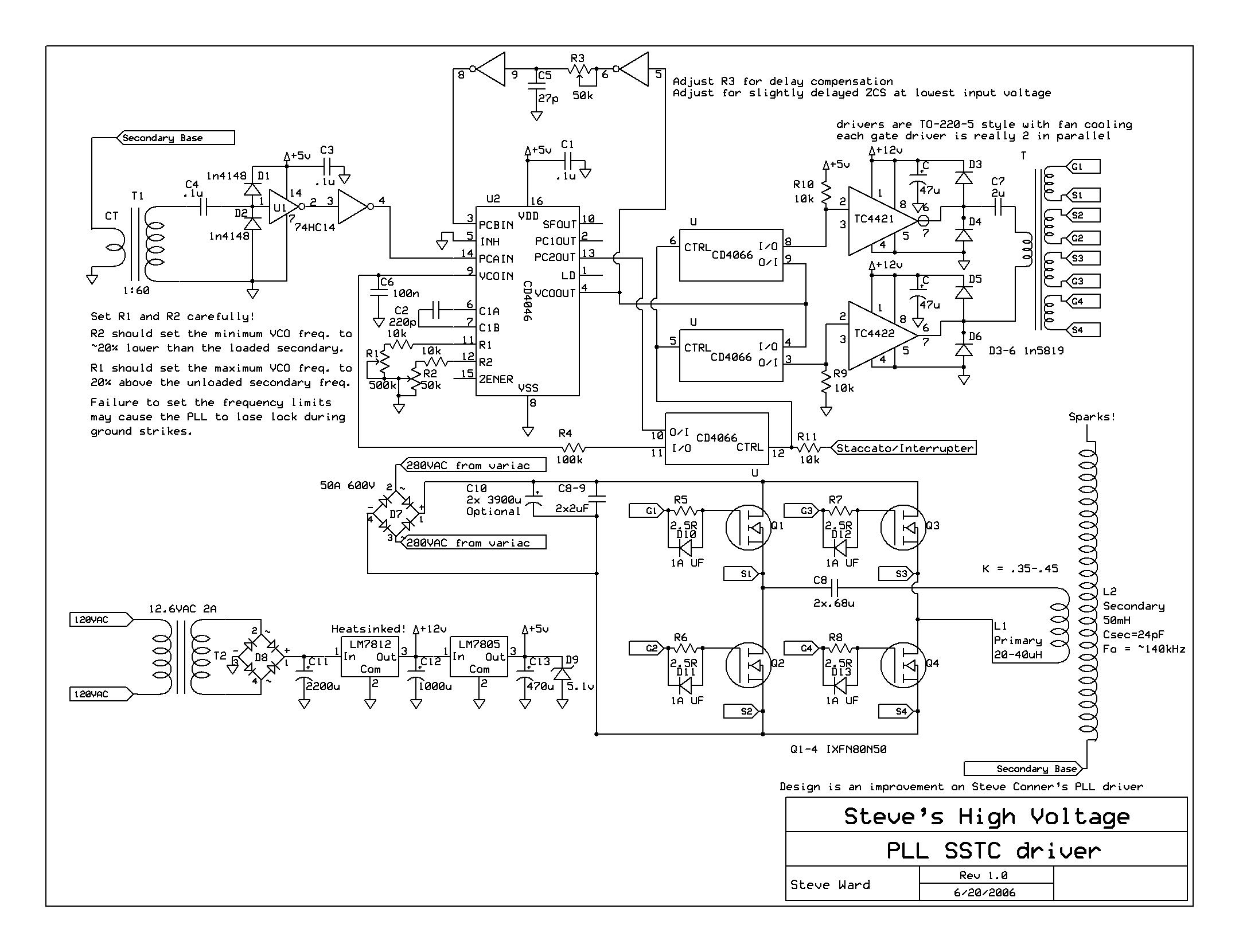
The coil is powered by a full bridge with four IRFP-460's. It is controlled by a version of Steve Ward's improved PLL driver. The driver is housed in the aluminium box with the fan (the fan blows directly on the gate driver chips). The relays switch the power to the bridge and are controlled by the "PWR" button on the control box.
The complete setup looks like this:
I believe the toroid is a bit oversized for this little secondary coil, but unfortunately I couldn't find aluminium ducting with a diameter less than 10 cm. With this topload, the resonant frequency is about 220 kHz. I aimed for 250 - 300 kHz, so I guess it's acceptable.
This is at 120 V AC input. My ultimate goal is to go all the way up to 230 V, but at about 150 V input the coil starts to stutter. I guess this is due to the feedback signal getting messed up. Also, I fear I need more turns on the primary to keep the bridge (or my fuses...) from blowing at the full input voltage.
So far I'm pretty pleased with the results. This coil is already much more impressive than my previous one and there is still room for improvement. One thing bugs me though: I haven't been ably to get current transformer feedback working. Currently the coil runs fine with antenna feedback but I would like to switch to a CT instead as I believe that may solve the "stuttering" problem at higher input voltages. My current CT has a 1:60 ratio. Unfortunately the PLL doesn't lock to the resonant frequency when I connect it (reversing the phasing makes no difference). Any suggestions will be appreciated.
Registered Member #1403
Joined: Tue Mar 18 2008, 06:05PM
Location: Denmark, Odense C
Posts: 1968
I like your style, its similar to how I have built SSTCs.
I was just wondering about the little piece of test pcb that you have two relays on, are the tracks underneath wide enough to handle lets say 3500W in CW mode? I could easily pull 2500W in CW mode with my similar coil.
Registered Member #91
Joined: Thu Feb 09 2006, 03:03PM
Location: The Netherlands
Posts: 45
wrote ...
I like your style, its similar to how I have built SSTCs.
Well, I have to admit I took some inspiration from your Kaizer SSTC's.
wrote ...
I was just wondering about the little piece of test pcb that you have two relays on, are the tracks underneath wide enough to handle lets say 3500W in CW mode? I could easily pull 2500W in CW mode with my similar coil.
I made the connections with solid copper wire meant for mains wiring, so I'm confident it can handle the power. I have to say though, that I underestimated the power levels a bit as I expected something like 1,5 kW at 100% input voltage.
This is what's inside those metal boxes:
I also tried snapping a picture of the bridge, which was difficult because it's mounted upside down.
Today, I got the CT feedback working. It turned out that it was a phasing issue after all. With the CT the coil works a little better than with the antenna.
However, I also had a bit of a setback. I was gradually increasing the power level. However, somewhere around 70% of the maximum input voltage the coil consistently stopped working and started producing a suspicious sound. I could not see anything going wrong though, so I kept running the coil at the point were it still worked OK (about 68% input voltage) and pushed the power levels up by adjusting the interrupter settings. Suddenly however, the toroid started smoking. I immediately shut everything down and after taking apart the secondary coil and toroid this is what I found:
It seems that the toroid got so hot that it started burning the PVC at the top of the secondary. Also, the glue I used on the toroid to attach pieces of aluminium foil (to make the point were the toroid is joined together look less of a mess...) melted. This caused an awful mess as you can see.
Is it normal that a toroid gets so hot that it can burn the PVC? Also, I think the coil crapping out at 70% input voltage may confirm my fear that this secondary really is too small to handle more than, say, 1 kW. What do you guys think?
Registered Member #91
Joined: Thu Feb 09 2006, 03:03PM
Location: The Netherlands
Posts: 45
I've given the failure some thought and there appeared to be internal arcover. This is probably also why the output suddenly disappeared: the voltage got so high that the preferred discharge path became something on the inside of my secondary instead of the air.
All this left a burned discharge path at the inside of the secondary. Fortunately, it looks like it didn't go entirely through so the wire is still undamaged and I can Dremel the charred track away.
What I'm going to do next (in a week or two):
- Repair the secondary - Mount the toroid in such a way that internal arcover is less likely (and also in such a way that I can actually see what's arcing to what) - Replace the glue on the toroid with something more heat resistant - Try again and hope it doesn't fail
Registered Member #91
Joined: Thu Feb 09 2006, 03:03PM
Location: The Netherlands
Posts: 45
Yesterday, I spent the whole day making a new toroid mounting (placing the toroid higher) and completing the base.
Here's a pic:
I managed to drop the toroid on two occasions yesterday, which is why it looks all messed up.
There is, however, a problem. When I still had the coil sitting next to the base, everything worked perfectly. With the new toroid mounting, the sparks were better than last time and toroid heating was considerabely less.
Now that I have mounted the coil on top of the base it only works for maybe 10 seconds and then stops. The only way to get it going again is to turn off the input voltage and wait until the voltage on the bridge has gone down to zero.
I'll have to investigate the cause of this. Right now, I'm thinking its some kind of interference issue.
This site is powered by e107, which is released under the GNU GPL License. All work on this site, except where otherwise noted, is licensed under a Creative Commons Attribution-ShareAlike 2.5 License. By submitting any information to this site, you agree that anything submitted will be so licensed. Please read our Disclaimer and Policies page for information on your rights and responsibilities regarding this site.


 My improved SSTC, first impressions


