If you need assistance, please send an email to forum at 4hv dot org. To ensure your email is not marked as spam, please include the phrase "4hv help" in the subject line. You can also find assistance via IRC, at irc.shadowworld.net, room #hvcomm.
Support 4hv.org!
Donate:
4hv.org is hosted on a dedicated server. Unfortunately, this server costs and we rely on the help of site members to keep 4hv.org running. Please consider donating. We will place your name on the thanks list and you'll be helping to keep 4hv.org alive and free for everyone. Members whose names appear in red bold have donated recently. Green bold denotes those who have recently donated to keep the server carbon neutral.
Special Thanks To:
Aaron Holmes
Aaron Wheeler
Adam Horden
Alan Scrimgeour
Andre
Andrew Haynes
Anonymous000
asabase
Austin Weil
barney
Barry
Bert Hickman
Bill Kukowski
Blitzorn
Brandon Paradelas
Bruce Bowling
BubeeMike
Byong Park
Cesiumsponge
Chris F.
Chris Hooper
Corey Worthington
Derek Woodroffe
Dalus
Dan Strother
Daniel Davis
Daniel Uhrenholt
datasheetarchive
Dave Billington
Dave Marshall
David F.
Dennis Rogers
drelectrix
Dr. John Gudenas
Dr. Spark
E.TexasTesla
eastvoltresearch
Eirik Taylor
Erik Dyakov
Erlend^SE
Finn Hammer
Firebug24k
GalliumMan
Gary Peterson
George Slade
GhostNull
Gordon Mcknight
Graham Armitage
Grant
GreySoul
Henry H
IamSmooth
In memory of Leo Powning
Jacob Cash
James Howells
James Pawson
Jeff Greenfield
Jeff Thomas
Jesse Frost
Jim Mitchell
jlr134
Joe Mastroianni
John Forcina
John Oberg
John Willcutt
Jon Newcomb
klugesmith
Leslie Wright
Lutz Hoffman
Mads Barnkob
Martin King
Mats Karlsson
Matt Gibson
Matthew Guidry
mbd
Michael D'Angelo
Mikkel
mileswaldron
mister_rf
Neil Foster
Nick de Smith
Nick Soroka
nicklenorp
Nik
Norman Stanley
Patrick Coleman
Paul Brodie
Paul Jordan
Paul Montgomery
Ped
Peter Krogen
Peter Terren
PhilGood
Richard Feldman
Robert Bush
Royce Bailey
Scott Fusare
Scott Newman
smiffy
Stella
Steven Busic
Steve Conner
Steve Jones
Steve Ward
Sulaiman
Thomas Coyle
Thomas A. Wallace
Thomas W
Timo
Torch
Ulf Jonsson
vasil
Vaxian
vladi mazzilli
wastehl
Weston
William Kim
William N.
William Stehl
Wesley Venis
The aforementioned have contributed financially to the continuing triumph of 4hv.org. They are deserving of my most heartfelt thanks.
Registered Member #1538
Joined: Thu Jun 12 2008, 07:28PM
Location: Bonn, Germany
Posts: 28
Hi everybody
Recently I’ve been building a small SSTC again. I wanted a Coil that would run anywhere without tuning it and could be audio modulated to play real music. I decided on using a PLL driver based on the famous cd4046, because I used it earlier and thought it would be adequate, but also because there is a lot of information on 4046 based drivers on the net. My design is very similar to Steve Conners first PLL driver, with one improvement you can also find in his later one (named MK2 PLL driver?): To maintain a phase shift of zero degrees independent of the secondaries exact resonant frequency I decided on using an active filter in the loop, which is basically an integrator. I drew a sketch of the oscillator section:
Please note that in my present design C2 and R3 are both left out (Value 0), I just added them to the picture to ease communication in the case they might become helpful. The first OpAmp is wired as an integrator, the second one is a simple inverter necessary to correct the integrators “sign†from “-Int†to “+Intâ€. I set everything up and it works well. The driver maintains the phasing set by P1 even under heavy changes of the secondaries resonant frequency and I ran a happy full-power test. Now I’m trying to find the best way to implement audio modulation.
So far, I see two practical ways to do that: first one is feeding the audio signal (via a capacitor) into pin 2 of the integrator. This would change the phasing, and therefore output power, just like P1 dose. However, the PLLs response will be limited by it’s settling time. Therefore the high frequency components might not get through the filter properly (right so far?) On the other hand, I could insert the audio signal into pin 5 (non-inverting input) of the inverter, or even directly into the 4046s VCO_IN pin. This way the low frequencies would become problematic, because the PLL would try to compensate for the “error†given by the audio signal.
Because both possibilities represent a trade-off, but the first one works best with a fast reacting PLL, which I think is desirable to limit the dynamic phase-error caused by streamer loading, ground arcs etc., I prefer this solution. But I’m not entirely sure if I didn’t miss something here. An integrator in the path of an audio signal just feels so wrong, and because I’m not too familiar with transfer functions I’m not sure if it can be made to work well at all.
Opinions on this, especially on how to dimension the filter section, or other ideas how to implement the audio modulation would be very helpful.
Registered Member #30
Joined: Fri Feb 03 2006, 10:52AM
Location: Glasgow, Scotland
Posts: 6706
Hey Timo
I must admit I never thought about this before.
The first possibility is probably best. To be sure, the signal gets integrated, but there's feedback around the integrator, through the Tesla coil. So the overall transfer function gets altered by the feedback to simply a low-pass filter. Most electronic circuits that use NFB, including audio power amps, even op-amps themselves, have an open-loop transfer function that looks like an integrator.
If there's not enough loop bandwidth to pass the high audio frequencies, then you can try speeding up the integrator. But be aware that the resonator's own unloaded Q also adds a phase shift to the loop that can approach 90 degrees at high frequencies. If you overcook the integrator, you'll get Nyquist instability. The "step network" C2, R3 you added may help here.
The unloaded Q is the relevant one, because the coil can't become loaded until it has started successfully, and it may not start succesfully if the PLL is unstable.
If you do it the second way, I'm pretty sure the audio signal will be differentiated, which is almost certainly not what you want.
Registered Member #152
Joined: Sun Feb 12 2006, 03:36PM
Location: Czech Rep.
Posts: 3384
Wouldn't it be best to just use the VCO function of the 4046 for audio input, without feedback?
Timo, I'm surprised it works that well, I've been thinking about the same circuit but I ditched the idea because for the feedback to lock, you need to have the phase around 0 degrees (or 180 if you swap something), and this is right at the edges of PC I.
Registered Member #1232
Joined: Wed Jan 16 2008, 10:53PM
Location: Doon tha Toon!
Posts: 881
Cheap FM radio transmitter designs that are based around a PLL, usually set the loop filter's response time to be below the lowest frequency of the modulating audio signal (i.e. below about 40Hz.) This prevents the control loop from fighting to "control out" the errors in the carrier frequency due to the audio modulating signal. (As you hinted, bass performance would suffer if the PLL loop bandwidth was too high, however it is worth bearing in mind that bass response is almost non-existant with a small audio-modulated SSTC anyway, so it might not be noticeable.)
The downside of this well slugged control loop response is that the VCO takes an age to get there when you specify a new operating frequency some distance from the present operating frequency.
Sometimes a non-linear "speed-up" circuit with two back-to-back signal diodes is placed in the feedback loop of the PLL. This has the effect of making the control loop bandwidth small for small-signals (so it doesn't control out the modulation) but large for large errors (so that it quickly jumps to the new operating frequency after a channel change.) Often a variable DC reference is injected into the VCO input also to quickly slew it to approximately the right operating frequency.
Registered Member #1538
Joined: Thu Jun 12 2008, 07:28PM
Location: Bonn, Germany
Posts: 28
Thank you all for the replies. I will try to commend them one after another.
. Luca I have to admit: the answer is “not reallyâ€. I used an old design aid that made me think the drawn filter would give a settling time of roughly 20us but it turned out to reduce the high frequency components audibly, so I guess it is slower.
.. Steve The way you describe it sounds a lot more reasonable. I already thought the integrator would become a low pass filter if you take feedback into account. But your explanation on possibility two really made me go the first way. I didn’t notice that, with feedback, the audio signal would get differentiated, at least for a fast enough loop. But once I thought about what would happen to a known input waveform, it sounds plausible. So I tried injecting an audio signal between P1 and R2 (to save one resistor, there was not enough free space for it) and I found the low pass filter to have a surprisingly low cut-off frequency, but than I recognised I forgot to drew a 100k potentiometer I placed right in front of the OpAmps input (might sound familiar to you, I felt inspired by your second driver…). Turning this to 0 Ohms gave me the mid-range, and changing C1 to 300pF made the whole thing sound relatively well. I even tried values down to 75pF to check for instabilities, but I found none. I settled on 300pF because I was not able to hear any improvement later on. So, special thanks to you!
... Dr. Kilovolt Yes, using only the VCO would be easier. I did this earlier, and found that the system would need to be retuned after moving it. That’s because with no audio signal in you need the driver to operate the coil “about have way down the resonance curves slopeâ€. If moving the coil changes its resonant frequency, the drivers mid-frequency will get to low or to high. Than you can’t crank the volume up entirely, because you might leave the resonance curves linear region. And you need full volume to predominate the arc’s hissing and crackling for a 300kHz Coil. And for the phase problem: I have a lot of delays, dominated by that of a fast optocoupler, between the oscillator and the bridge. This gives additional phase shift. I found the optocoupler to be helpful during my initial tests using only the VCO, because the 4046 it is so very sensitive, and left it in place. I can try what happens if I short it out… But also remember I’m NOT driving the Coil at F_res.
.... Richie A slow responding PLL would be the other way, with the downside of slow compensation of streamer loading, ground arcs etc. However, it might still be a good idea because my main issue was to compensate for changes made by moving the coil, which is a REALLY slow change compared to the audio signal A “speed up†circuit, on the other hand, might get difficult, because the frequency changes generated by the audio signal are in no way smaller than these necessary to compensate a relocation. However, I might try a slow PLL later.
But for now I will enjoy what I have, and you can do the same, if you like to. I tried recording the coil in action, and because the sound quality of my cam was even poorer than the coil’s, I dug out a microphone and made a small pure-audio recording, that doesn’t really sound like the coil in reality dose, but at least it’s not worse:
]sound.mp3[/file]
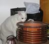
At the moment a simple picture should be sufficient to show what it looks like:
Registered Member #1232
Joined: Wed Jan 16 2008, 10:53PM
Location: Doon tha Toon!
Posts: 881
If you want to get the best sound quality it would be worth thinking about taking feedback from the thing that you want to control. Then making this part of a closed loop control system to make it track your audio input waveform.
At the moment you are trying to make the frequency track the average resonant frequency of the resonator, _but_ then also introduce AC modulation to the frequency in the hope that this will then modulate the arc current and result in audio! It's quite a long-winded convoluted way to get where you want. It also has two contridicting requirements, to track the resonant frequency precisely, and to deviate from this to introduce audio modulation!
If you think about it, it is the in-phase component of the current out of the inverter that contributes real power and heats the air in the TC discharge. When you detune the drive frequency, you are really modulating the in-phase current draw because the phase angle of the current drawn by the resonator changes. You can measure the in-phase "REAL POWER" out of the inverter (and ultimately supplied to the arc) quite easily. You simply measure the instantaneous output voltage of the inverter and the instantaneous inverter output current, then multiply these together. (This can easily be done with a mini-circuits diode balanced mixer, as well as many four-quadrant multiplier ICs.) The resulting signal from this "synchronous demodulation" process is proportional to the current in the TC discharge.
Since arc current is what you want to control, you use this as your feedback signal in a negative feedback closed-loop control scheme. The audio signal is the reference ("demand" or "set-point") for the control system and this "arc current" signal is the output of the system being fed back to the error amplifier. The error amplifier generates a signal that is used to drive a VCO which determines the switching frequency. The closed-loop control continually acts to servo the VCO frequency such that the "arc current" measurement from the inverter output is made equal to the incoming audio waveform reference.
This should yield extremely low distortion audio since you are directly controlling the parameter you want, rather than relying on non-linear "slope demodulation" to convert FM to AM. It will also naturally track the resonant frequency of the coil as you move it from one environment to another because it will simply keep decreasing the VCO operating frequency until the required current draw is achieved.
It has all of the advantages of low-level drive-side FM modulation to achieve the singing arc, but will automatically implement frequency tracking too. Edit: The closed-loop control should also help with "regulating out" any remaining hum due to mains ripple in the DC bus voltage.
FWIW, A similar technique is used in high-power AM broadcast transmitters where the transmitter's output current (or antenna current) is sampled, demodulated and fed-back to the modulator to increase linearity of the system and reduce distortion in the final broadcast envelope.
Registered Member #1538
Joined: Thu Jun 12 2008, 07:28PM
Location: Bonn, Germany
Posts: 28
Well, yes, I think this would be a conceptually better design. I thought about a possibility to implement negative feedback to linearize the overall system but I gave up on this because I couldn’t think of an easy way to measure the “arc powerâ€, and because there would still be two unknown factors: the amount of hissing and crackling the arc would produce anyways, and the process that actually converts electric power into sound waves. I don’t know if (and why?) this process is free of distortion, while it seems to depend on a lot of hard to describe characteristics. And a higher operating frequency, which would reduce the “arc noiseâ€, can’t be used because I want the discharges to look at least a little lightning-like.
However, the assumption that “arc power†is proportional to the real power delivered to the primary coil surely is appropriate, and I like your idea of using it as a feedback signal. This would give negative feedback across the whole “amplifierâ€, if I may compare this to building HiFi equipment. But as being also the manufacturer of the “loudspeaker†I would have to ensure I don’t distort the signal there.
The concept you proposed is so different from what I’ve done so far, that I will not change my design if I’m able to make it work well enough the way it is right now. But I will keep this in mind and might give it a try in the future, because having build both would allow me to evaluate how bad the resonance curves slope distorts the audio. In addition the requirement of a big DC smoothing cap is a problem with my design, and as you mentioned negative feedback would allow a larger supply voltage ripple. If you look at the picture I uploaded carefully you can see that I had to add the two big blue capacitors to ease making measurements at low operating voltages, because the current draw (and therefore the voltage ripple) is nearly constant over the whole input voltage range. There is a 1000uF 400V lytic on board, and if it has to do the job on it’s own, you can hear a little hum at high power levels. At reduced input voltages the hum becomes more significant.
My next steps will be making a pcb for the whole driver (no stacking of boards anymore, see pic) and building a housing. Than I can mount a fan to cool the MOSFET’s and, more important, the secondary. It heats up badly during long runs at high power, which is not surprising for a coil running CW. Also the primary and secondary coils need to be changed to look a little nicer. This was intended to be a show-off coil
Registered Member #1232
Joined: Wed Jan 16 2008, 10:53PM
Location: Doon tha Toon!
Posts: 881
Don't forget that for "slope detection" to work you want the quiescent operating frequency to be half-way up one of the slopes of the resonators bell-shaped response. The audio then causes FM that works up and down the slope on that side of the peak. Just a reminder that you don't want the quiescent point to be at the resonant peak. Your PLL needs to be designed with this offset in mind if you are controlling the frequency.
There are lots of ways to reduce the hum from the DC bus. If you are using single-phase power I would use an active PFC boost converter to generate the DC bus. You can then either use negative feedback, or DC bus feedforward techniques to greatly reduce audible hum at the output.
If you can use 3-phase power then you can get away with a much smaller DC bus cap because the bus voltage won't ripple all the way down to zero. Again the remaining ripple can probably be largely cancelled out via voltage-feedforward or output feedback techniques.
As for the linearity of "slope detection" when applied to a TC with corona breakout: I found that it is horrendously non-linear when you drive the TC resonator on the low side of its resonant peak because the corona breakout makes the resonant frequency unstable in this region. The corona itself causes a form of hysteresis in the resonant frequency where it drops suddenly once there is breakout, and the air remains ignited as the power level decreases, then finally the corona goes out and the power must be increased again to re-light it! Not good behaviour for audio modulation, or for the inverter driving it!
On the high-side of the resonant peak the slope-detection is much more linear. The detuning from the corona breakout is self limiting on the high-side so it doesn't cause as much distortion.
It's quite hard to analyse this stuff though because as you drive the resonator closer to it's natural resonant frequency the corona grows causing the natural resonant frequency to drop and the Q factor to fall. So changing the drive frequency actually changes the shape and location of the resonant frequency of the load! This complex interaction is the reason why I beleive negative feedback would be beneficial if audio clarity is your prime concern.
Registered Member #1538
Joined: Thu Jun 12 2008, 07:28PM
Location: Bonn, Germany
Posts: 28
Again I have to say: I absolutely agree with you! I designed the oscillator to have a quiescent frequency slightly above F-res. and tuned it to operate the coil at the high-frequency end of the resonance curve, mainly because a slightly capacitive load should fit the inverter better. However, I tried the other side with a my simple vco based scheme and found the audio to be nearly unrecognisable, because the arc turns on and of suddenly over and over again resulting in bad “crackling†mixed with massive distortions!
For DC bus regulation: I was aware of these possibilities, but because this isn’t ever going to become a commercial design I thought I would just accept the size and price of a big smoothing cap. However, I was thinking about an easy way to reduce inrush current lately and found that a simple resistor/relay solution might result in a part count comparable to a simple active PFC! So, may be I will rethink this.
But as a reason for posting all this accordance: I encountered a question and may be you can help me with that: I found that building the PLL with a frequency range way bigger than the allowable frequency shift of the secondary in mind gives better audio quality, which appears weird to me. The Coil operates between, roughly, 340kHz (nearly no output) and 320kHz (resonant peak). While having the centre frequency between these two I found using a range of 250 to 410 kHz to be a little better than any smaller one. I thought that for an ideal system it shouldn’t matter, while for a real system it typically is a good idea to use the whole input range to map the desired dynamic range of the system (Did I put this in understandable words?). Might this be because the integrator doesn’t have to change it’s output that much? Or what is going on?
This site is powered by e107, which is released under the GNU GPL License. All work on this site, except where otherwise noted, is licensed under a Creative Commons Attribution-ShareAlike 2.5 License. By submitting any information to this site, you agree that anything submitted will be so licensed. Please read our Disclaimer and Policies page for information on your rights and responsibilities regarding this site.


 Audio modulation of PLL with active loop filter