If you need assistance, please send an email to forum at 4hv dot org. To ensure your email is not marked as spam, please include the phrase "4hv help" in the subject line. You can also find assistance via IRC, at irc.shadowworld.net, room #hvcomm.
Support 4hv.org!
Donate:
4hv.org is hosted on a dedicated server. Unfortunately, this server costs and we rely on the help of site members to keep 4hv.org running. Please consider donating. We will place your name on the thanks list and you'll be helping to keep 4hv.org alive and free for everyone. Members whose names appear in red bold have donated recently. Green bold denotes those who have recently donated to keep the server carbon neutral.
Special Thanks To:
Aaron Holmes
Aaron Wheeler
Adam Horden
Alan Scrimgeour
Andre
Andrew Haynes
Anonymous000
asabase
Austin Weil
barney
Barry
Bert Hickman
Bill Kukowski
Blitzorn
Brandon Paradelas
Bruce Bowling
BubeeMike
Byong Park
Cesiumsponge
Chris F.
Chris Hooper
Corey Worthington
Derek Woodroffe
Dalus
Dan Strother
Daniel Davis
Daniel Uhrenholt
datasheetarchive
Dave Billington
Dave Marshall
David F.
Dennis Rogers
drelectrix
Dr. John Gudenas
Dr. Spark
E.TexasTesla
eastvoltresearch
Eirik Taylor
Erik Dyakov
Erlend^SE
Finn Hammer
Firebug24k
GalliumMan
Gary Peterson
George Slade
GhostNull
Gordon Mcknight
Graham Armitage
Grant
GreySoul
Henry H
IamSmooth
In memory of Leo Powning
Jacob Cash
James Howells
James Pawson
Jeff Greenfield
Jeff Thomas
Jesse Frost
Jim Mitchell
jlr134
Joe Mastroianni
John Forcina
John Oberg
John Willcutt
Jon Newcomb
klugesmith
Leslie Wright
Lutz Hoffman
Mads Barnkob
Martin King
Mats Karlsson
Matt Gibson
Matthew Guidry
mbd
Michael D'Angelo
Mikkel
mileswaldron
mister_rf
Neil Foster
Nick de Smith
Nick Soroka
nicklenorp
Nik
Norman Stanley
Patrick Coleman
Paul Brodie
Paul Jordan
Paul Montgomery
Ped
Peter Krogen
Peter Terren
PhilGood
Richard Feldman
Robert Bush
Royce Bailey
Scott Fusare
Scott Newman
smiffy
Stella
Steven Busic
Steve Conner
Steve Jones
Steve Ward
Sulaiman
Thomas Coyle
Thomas A. Wallace
Thomas W
Timo
Torch
Ulf Jonsson
vasil
Vaxian
vladi mazzilli
wastehl
Weston
William Kim
William N.
William Stehl
Wesley Venis
The aforementioned have contributed financially to the continuing triumph of 4hv.org. They are deserving of my most heartfelt thanks.
Registered Member #834
Joined: Tue Jun 12 2007, 10:57PM
Location: Brazil
Posts: 644
The simulation below shows the strange effect of reducing the inductance of the series inductor below a certain value. The circuit enters an irregular oscillatory mode draining a huge current: The plot shows the input current. With 67 uH of inductance in the series inductor, the circuit works correctly. With 66 uH, it doesn't. This is not a regular quasi-linear oscillator. There is no feedback when the diodes are not conducting. It is a strongly nonlinear oscillator with a structure quite different from classical structures (that I know, at least). It works correctly with two uncoupled inductors instead of the center-tapped primary coil. Two flybacks (AC type) could then be used with it, doubling the output, and in this case the series inductor is not necessary.
Registered Member #192
Joined: Fri Feb 17 2006, 03:08AM
Location: Canada
Posts: 44
Even with a DVM it's hard to read the input current, mine gave erronous readings. I end up using an external current shunt and reading the mV output and then converting to amps.
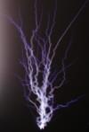
With My zvs I could draw 5 inch long, thick arcs. My power supply was 36 volts DC off of 3 - 12volt batteries. I changed the resonant cap, added bypass caps to the supply ,changed the gate resistors and zeners all to maximize power output. I've measured 13 amps when I drew the arc out to it's full length. That works out to 468 watts max.
Registered Member #543
Joined: Tue Feb 20 2007, 04:26PM
Location: UK
Posts: 4992
Aha! You have obviously discovered an electronic secret which can not be revealed by scientific measurement techniques alone. If we take a very ordinary 21kV LOPT, rated by its manufacturer such as HR Diemen at 90W, shouldn't we at least wonder how the tiny wires of the secondary could really support 1kw or more as has been claimed?
The process of power amplification for the >100W input by the <1kW output seems to me a mystical and magical thinking, where, to put the kindest complexion on experimental results, arc length is wilfully confused with the dielectic breakdown of air in order to inflate air.
But I'm not an HV or Tesla girl, so my observations could well be out of order here.
Registered Member #152
Joined: Sun Feb 12 2006, 03:36PM
Location: Czech Rep.
Posts: 3384
Proud Mary wrote ...
Aha! You have obviously discovered an electronic secret which can not be revealed by scientific measurement techniques alone. If we take a very ordinary 21kV LOPT, rated by its manufacturer such as HR Diemen at 90W, shouldn't we at least wonder how the tiny wires of the secondary could really support 1kw or more as has been claimed?
In the same way as a 500VA transformer will run at 5000VA, for a limited time? 1kW seems a lot to me too, but obviously this depends on the construction of the transformers. Most diode split transformers of mine can take a few hundred watts. Some are overrated more, some less (for their real job in which they need to run tens of thousands hours without a failure). Another factor is that these huge output powers come from running the transformer in forward mode, where the power is supplied when the diodes are conducting, not in flyback mode like in the TV where the power is extracted just from the energy stored in the core during the time the switching transistor is off. This allows for greater power throughput and less heating of the secondary winding, because it conducts for longer time. Also we use just the secondary winding, not the original primary and auxiliary windings, so these do not contribute to the heating of the integrated transformer.
Registered Member #30
Joined: Fri Feb 03 2006, 10:52AM
Location: Glasgow, Scotland
Posts: 6706
Antonio wrote ...
This is not a regular quasi-linear oscillator. There is no feedback when the diodes are not conducting. It is a strongly nonlinear oscillator with a structure quite different from classical structures
Yes, if you want to keep your sanity, just don't think too hard about how it works! In my earlier discussion, I don't cover the feedback aspects of the circuit: it might as well be driven from an external fixed oscillator set to the LC resonance frequency.
This is deliberate because any attempt to explain how the feedback really works would just confuse everyone. OK, what I mean is that I don't really understand how it works.
But consider that one or other of the diodes is always conducting, and the circuit resembles the old two-transistor astable multivibrator.
Even if the two inductors were uncoupled magnetically, they'd still be coupled through the tank capacitor.
Registered Member #152
Joined: Sun Feb 12 2006, 03:36PM
Location: Czech Rep.
Posts: 3384
Steve McConner wrote ...
This is deliberate because any attempt to explain how the feedback really works would just confuse everyone. OK, what I mean is that I don't really understand how it works.
The feedback is quite simple - when transistor 1 is conducting, it keeps transistor 2 off through the diode. The voltage on tr.2's drain is high enough so tr.1's gate is pulled up with the gate pullup resistor. When the voltage on tr.2 falls below tr.1's gate threshold voltage minus the diode drop, tr. 1 is turned off. Well, kind of. During the phase the primary voltage is near zero, both transistors are actually in linear mode with the voltage drop on them set by their gate threshold voltages (again minus the diode drops). This is the moment I believe the circuit might enter the "parasitic oscillation" mode, where the transistors oscillate just with their delay times, only possibly damped by the gate resistors. This is probably why higher gate resistor values seem to decrease the probability of these oscillations. When the circuit gets past this linear phase (the primary voltage has risen enough in the other direction), transistor 2 is now conducting and keeps transistor 1 off until the voltage falls back again.
EDIT: I wanted to add that maybe putting small capacitors across D-S of both transistors could decrease or eliminate the chance of the unwanted oscillations, but I have not tried this.
Registered Member #1389
Joined: Thu Mar 13 2008, 12:50AM
Location: Pittsburgh, PA
Posts: 346
Wow, I apologize for not putting out a basis for my 500-1kW guess for arc power. I am told that this is not the correct way of measuring real power, but for now it is the closest I can get with the tools I have (getting a kill-a-watt soon). My measured DC voltage on the bus caps was 155VDC and measuring the current before the input inductor with a 2m resistor showed a DC current of 11A (22mV).
Registered Member #30
Joined: Fri Feb 03 2006, 10:52AM
Location: Glasgow, Scotland
Posts: 6706
The unspoken assumption behind the kill-a-watt (or DC bus volts * amps) method is that most of the power going into the circuit is coming out as arcs.
Given that a flyback is a physically small object that can't handle much heat without burning up, that's probably a reasonable assumption. If the flyback doesn't melt after a few minutes, and you measure 1kW going into it, then maybe 900W must be coming out.
If you have huge heatsinks on your driver transistors and they're still getting stinking hot, that's a different matter.
Registered Member #1389
Joined: Thu Mar 13 2008, 12:50AM
Location: Pittsburgh, PA
Posts: 346
I understand that, Steve. That's why my conservative guess was .5-1kW of arc power with measured 1750VA of measured power in. I can tell you the heat of the arc was more than enough to melt a couple of centimeters of my 14AWG ground point over the course of it's life. My little heatsink only gets lukewarm. Of course, at this point, it's all speculation, as the flyback ultimately did overheat after a 3 minute run with 155V in.
Registered Member #192
Joined: Fri Feb 17 2006, 03:08AM
Location: Canada
Posts: 44
I have no doubt that your output power was 1.5 to 2 times greater than what I was getting out of my zvs flyback circuit. How the flyback can handle that much punishment is beyond me. I just hope that when I bring it over to someone's place to do a demonstration that it doesn't burst into flames. (I do worry about that!) :-0
This site is powered by e107, which is released under the GNU GPL License. All work on this site, except where otherwise noted, is licensed under a Creative Commons Attribution-ShareAlike 2.5 License. By submitting any information to this site, you agree that anything submitted will be so licensed. Please read our Disclaimer and Policies page for information on your rights and responsibilities regarding this site.


 Very Very High Power Flyback Driver


 In my earlier discussion, I don't cover the feedback aspects of the circuit: it might as well be driven from an external fixed oscillator set to the LC resonance frequency.