If you need assistance, please send an email to forum at 4hv dot org. To ensure your email is not marked as spam, please include the phrase "4hv help" in the subject line. You can also find assistance via IRC, at irc.shadowworld.net, room #hvcomm.
Support 4hv.org!
Donate:
4hv.org is hosted on a dedicated server. Unfortunately, this server costs and we rely on the help of site members to keep 4hv.org running. Please consider donating. We will place your name on the thanks list and you'll be helping to keep 4hv.org alive and free for everyone. Members whose names appear in red bold have donated recently. Green bold denotes those who have recently donated to keep the server carbon neutral.
Special Thanks To:
Aaron Holmes
Aaron Wheeler
Adam Horden
Alan Scrimgeour
Andre
Andrew Haynes
Anonymous000
asabase
Austin Weil
barney
Barry
Bert Hickman
Bill Kukowski
Blitzorn
Brandon Paradelas
Bruce Bowling
BubeeMike
Byong Park
Cesiumsponge
Chris F.
Chris Hooper
Corey Worthington
Derek Woodroffe
Dalus
Dan Strother
Daniel Davis
Daniel Uhrenholt
datasheetarchive
Dave Billington
Dave Marshall
David F.
Dennis Rogers
drelectrix
Dr. John Gudenas
Dr. Spark
E.TexasTesla
eastvoltresearch
Eirik Taylor
Erik Dyakov
Erlend^SE
Finn Hammer
Firebug24k
GalliumMan
Gary Peterson
George Slade
GhostNull
Gordon Mcknight
Graham Armitage
Grant
GreySoul
Henry H
IamSmooth
In memory of Leo Powning
Jacob Cash
James Howells
James Pawson
Jeff Greenfield
Jeff Thomas
Jesse Frost
Jim Mitchell
jlr134
Joe Mastroianni
John Forcina
John Oberg
John Willcutt
Jon Newcomb
klugesmith
Leslie Wright
Lutz Hoffman
Mads Barnkob
Martin King
Mats Karlsson
Matt Gibson
Matthew Guidry
mbd
Michael D'Angelo
Mikkel
mileswaldron
mister_rf
Neil Foster
Nick de Smith
Nick Soroka
nicklenorp
Nik
Norman Stanley
Patrick Coleman
Paul Brodie
Paul Jordan
Paul Montgomery
Ped
Peter Krogen
Peter Terren
PhilGood
Richard Feldman
Robert Bush
Royce Bailey
Scott Fusare
Scott Newman
smiffy
Stella
Steven Busic
Steve Conner
Steve Jones
Steve Ward
Sulaiman
Thomas Coyle
Thomas A. Wallace
Thomas W
Timo
Torch
Ulf Jonsson
vasil
Vaxian
vladi mazzilli
wastehl
Weston
William Kim
William N.
William Stehl
Wesley Venis
The aforementioned have contributed financially to the continuing triumph of 4hv.org. They are deserving of my most heartfelt thanks.
Registered Member #1889
Joined: Mon Dec 29 2008, 07:36AM
Location:
Posts: 55
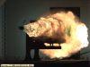
So I have built now my third flyback driver and despite finally buying a kit with everything already 'ready to solder' I keep getting the same results. When I turn on the flyback nothing ever happens but as soon as I turn it off it arcs to the negative lead. I understand that its the coil discharging because of the collapsing magnetic field but I'm still not getting the continuous spark its supposed to produce. I'm using a 24v DC input for the circuit and I followed the exact schematic provide by the kit (555 timer for the frequency control). Sadly enough even when I build my transistor driven flyback it still yielded the same results.
Registered Member #1225
Joined: Sat Jan 12 2008, 01:24AM
Location: Beaumont, Texas, USA
Posts: 2253
Pictures? Schematics?
We need to know the part number of the switching transistor. If you are using a BJT, you may want to switch to a mosfet, they seemed to die less on me when i first built flyback drivers. I never use BJTs, only mosfets and IGBT's.
Registered Member #162
Joined: Mon Feb 13 2006, 10:25AM
Location: United Kingdom
Posts: 3141
I don't know what your circuit is, but a 555 is rated for 18V maximum, so unless there is a separate/lower voltage supply for the 555, it's probably dead.
Registered Member #1889
Joined: Mon Dec 29 2008, 07:36AM
Location:
Posts: 55
@Sulaiman
There is a voltage regulator in the circuit for the logic ICs if you take a look at the schematic posted in the pdf a little ways down this post.
@Arcstarter
So I took a closer look at the part number for the 'high voltage transistor' (or so it was listed as) in the kit and much to my surprise it was an IGBT. Which is nice because they usually do better than regular transistors or even MOSFETs at higher voltages. But the downside is their Emitter-Collector breakdown voltage quite plainly blows (24v for mine). So I assume when I plugged in that 30v DC power supply to the board hoping it could take another 6v and the rtards who built it didn't borderline their design I was tragically wrong Now I'm going to see if I can replace the original 390v IGBT with a bit more robust 500v MOSFET that I pulled out of an old TV set board and hopefully that will work.
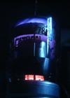
Oh and here's the kit schematics and pics and stuff:
The part number for the IGBT which the kit came with is V5036P Datasheet:
The one I'm going to try and replace it with is 2SK2662 Datasheet:
Let me know if it will work because I figure it will because of the vast similarities between IGBTs and MOSFETs.
@Dr. Kilovolt
You were spot on. Totally forgot about that but turns out your 100% correct.
------------------------
By the way, thank you guys for the quick responses and the very helpful suggestions.
Registered Member #180
Joined: Thu Feb 16 2006, 02:12AM
Location: Ontario, Canada
Posts: 187
It doesn't make sense to power the low power side (the side with the IC's, the 555 and 4049) with 24 volts, because then the Vreg needs to burn away 19 volts at what ever current the circuit uses, which most likely means it will get VERY hot and shut itself off. This part of the circuit should be powered from a 12V supply or less, the way it is wired now it only gets 5 volts anyways.
Also I don't think you got your Emitter-Collector breakdown voltage right, if you said you have a 390 volt IGBT then that is the Emitter-Collector breakdown voltage. The 24 volts should be from the Gate to the Emitter, and with your circuit it won't ever see above 5V. Now I'm not entirely sure but I would think it would be better to drive the IGBT with more then 5V but you would have to look at the datasheet.
The HV side of the circuit should be powered by 24 + volts, but that should be kept seperate from the control side as I said before.
EDIT
Just checked the datasheet you linked, and yes the Emitter-Collector breakdown voltage is 390V not 24V, and I was wrong, 5V is plenty to drive this IGBT, it's designed for driving ignition coils so I would say its perfect for this application.
Registered Member #152
Joined: Sun Feb 12 2006, 03:36PM
Location: Czech Rep.
Posts: 3384
The IGBT's are usually not avalanche rated, which mean they'll blow up if you exceed the breakdown voltage. MOSFETs, on the other hand, just clamp the voltage like a zener diode and dissipate it as a heat.
But I think I see a SERIOUS problem with the schematic, the circuit puts only 5 volts to the gate?! This is by far not enough to turn on an IGBT. 10V is absolute minimum, 15V is preferred. 5V probably just puts it in linear mode so it doesn't switch much power and gets hot.
Registered Member #180
Joined: Thu Feb 16 2006, 02:12AM
Location: Ontario, Canada
Posts: 187
I also thought the same thing Dr.Kilovolt, but if you check the datasheet for that IGBT, page 4 figure 8, the graph doesn't even go to 5 volts. At 2.5 volts on the gate your Ic is already at 10, and I don't even think you can push that much through the iggy with this driver, so although it seems strange 5volts is fine.
This site is powered by e107, which is released under the GNU GPL License. All work on this site, except where otherwise noted, is licensed under a Creative Commons Attribution-ShareAlike 2.5 License. By submitting any information to this site, you agree that anything submitted will be so licensed. Please read our Disclaimer and Policies page for information on your rights and responsibilities regarding this site.


 Flyback Driver Kit Help


 Now I'm going to see if I can replace the original 390v IGBT with a bit more robust 500v MOSFET that I pulled out of an old TV set board and hopefully that will work.