If you need assistance, please send an email to forum at 4hv dot org. To ensure your email is not marked as spam, please include the phrase "4hv help" in the subject line. You can also find assistance via IRC, at irc.shadowworld.net, room #hvcomm.
Support 4hv.org!
Donate:
4hv.org is hosted on a dedicated server. Unfortunately, this server costs and we rely on the help of site members to keep 4hv.org running. Please consider donating. We will place your name on the thanks list and you'll be helping to keep 4hv.org alive and free for everyone. Members whose names appear in red bold have donated recently. Green bold denotes those who have recently donated to keep the server carbon neutral.
Special Thanks To:
Aaron Holmes
Aaron Wheeler
Adam Horden
Alan Scrimgeour
Andre
Andrew Haynes
Anonymous000
asabase
Austin Weil
barney
Barry
Bert Hickman
Bill Kukowski
Blitzorn
Brandon Paradelas
Bruce Bowling
BubeeMike
Byong Park
Cesiumsponge
Chris F.
Chris Hooper
Corey Worthington
Derek Woodroffe
Dalus
Dan Strother
Daniel Davis
Daniel Uhrenholt
datasheetarchive
Dave Billington
Dave Marshall
David F.
Dennis Rogers
drelectrix
Dr. John Gudenas
Dr. Spark
E.TexasTesla
eastvoltresearch
Eirik Taylor
Erik Dyakov
Erlend^SE
Finn Hammer
Firebug24k
GalliumMan
Gary Peterson
George Slade
GhostNull
Gordon Mcknight
Graham Armitage
Grant
GreySoul
Henry H
IamSmooth
In memory of Leo Powning
Jacob Cash
James Howells
James Pawson
Jeff Greenfield
Jeff Thomas
Jesse Frost
Jim Mitchell
jlr134
Joe Mastroianni
John Forcina
John Oberg
John Willcutt
Jon Newcomb
klugesmith
Leslie Wright
Lutz Hoffman
Mads Barnkob
Martin King
Mats Karlsson
Matt Gibson
Matthew Guidry
mbd
Michael D'Angelo
Mikkel
mileswaldron
mister_rf
Neil Foster
Nick de Smith
Nick Soroka
nicklenorp
Nik
Norman Stanley
Patrick Coleman
Paul Brodie
Paul Jordan
Paul Montgomery
Ped
Peter Krogen
Peter Terren
PhilGood
Richard Feldman
Robert Bush
Royce Bailey
Scott Fusare
Scott Newman
smiffy
Stella
Steven Busic
Steve Conner
Steve Jones
Steve Ward
Sulaiman
Thomas Coyle
Thomas A. Wallace
Thomas W
Timo
Torch
Ulf Jonsson
vasil
Vaxian
vladi mazzilli
wastehl
Weston
William Kim
William N.
William Stehl
Wesley Venis
The aforementioned have contributed financially to the continuing triumph of 4hv.org. They are deserving of my most heartfelt thanks.
Registered Member #1403
Joined: Tue Mar 18 2008, 06:05PM
Location: Denmark, Odense C
Posts: 1968
Introduction The motivation for this little project is to gain experience in designing from scrath and work out a general guide to design a TL494 driver. I want to do this because the TL494 IC is widely used but often with little to none description of how it is set up to work with variable frequency and duty cycle. Almost every man uses the IC differently when it comes to these two features which makes it hard for some of us amateurs to understand how it works.
This driver will be used with the flyback I received from Dr. Spark, to power my long forgotten and on halt 600kV marx generator :)
Goal With simple and common tools/components, to design a flyback driver section with mosfet driver ICs to drive a external bridge board where the GDT is also located. Variable dutycycle 0 to 45% Variable frequency 50 to 150 kHz
Tools available Handtools and drill 15MHz 2-channel dualtrace scope Fluke T5-600 multimeter Cheap chinese LCR meter PCB board, permanent marker and FeCl3
Progress 24th may 2009 Design the TL494 section according to goals using the Texas Instruments design guide.
25th may 2009 Build breadboard prototype with TL494 Test oscillator and outputs
26th may 2009 Design PCB for driver section
27th may 2009 Etch and assemble driver section PCB
29th may 2009 Test driver section on a halfbridge
3rd june 2009 Design PCB for halfbridge section Etch and assemble halfbridge section PCB
Todo: Final product: TL494 flyback driver running a halfbridge section connected to a flyback transformer.
Designing the TL494 section
I wanted the driver to be able to have a variable frequency fromm 50kHz to 150kHz, so lets find out the values needed.
The output control on pin 13 is set high from the 5V reference voltage on pin 14, this makes the two output transistors work in push pull mode, which will be used to drive each their non-inverted mosfet driver ic.
For further study and experiments the output control can be tied to ground to enable single end mode, the two output transistors will be in phase and can be paralleled for a higher output driving current.
Its possible to implement features as softstart and overvoltage , -current protection with the dead time control on pin 4, I have chosen to wire this to ground which enables maximum duty cycle in the aspect this will be a modestly powered flyback for a stable, but adjustable high voltage supply.
The outputs are each connected to the positive rail through a 150R 2W pullup resistor to bring the output signal up in amplitude.
Frequency
The frequency is determined by Rt (pin 6) and Ct (pin 5) as a normal RC timing circuit.
I choose to use a 1nF capacitor, so I can calculate the resistor values and find what potentiometer is needed, I aimed to use a 10K potentiometer as I had them at hand.
the frequency in push-pull operations are f = 1/(2Rt * Ct)
Resistor value for 50kHz = (1/(50000 * (1 * 10^-9)))/2) = 10K (rounded)
Resistor value for 150kHz = (1/(150000 * (1 * 10^-9)))/2) = 3K3 (rounded)
Another reason to use 150KHz as the maximum value is that the TL494 changes the minimum deadtime period for frequencies above to insure proper switching.
So the lowest value will be a Rt = 3K3
The frequency can be lower than 50kHz without complications, so combined with a 10K potentiometer the low frequency will be = 1/((2 * 13300) * (1 * 10^-9)) ~ 38 kHz.
Duty cycle
The TL494 have two error amplifiers which I for the sake of leaving no inputs floating have paralleled.
To adjust the duty cycle I have set up the error amplifier as a voltage follower, the feedback from the opamp is tied to the - input, that way the output voltage will be just under the input voltage. With a potentiometer and a resistor I can vary the input voltage from 0,5V to 4,76V, this voltage span is enough to adjust the duty cycle from 0 to 43%. This is acceptable in respect to the design goals.
Build breadboard prototype with TL494 Test oscillator and outputs
The breadboard is populated, the tape is to hold the timing capacitor in place since it have got short legs
Here we can see the output waveform without pullup resistors, it is about 38kHz at 43% duty cycle
Here we can see the output waveform without pullup resistors, it is about 38kHz at 5-7% duty cycle
Here we can see the output waveform without pullup resistors, it is about 150kHz at 43% duty cycle
Design PCB for driver section
Designing a PCB takes time to get right, and it might also take a couple of etches to elimate all the errors and corrections if you have to make changes due to new ideas.
I will not go into detail with best practises for PCB design as I do not know them all, but keep supply and power traces as wide as possible and avoid sharp corners.
Etch and assemble driver section PCB
I printed out the trace layout from ExpressPCB, which do not have the option to mirror the traces, so I used a black marker to paint through the paper so I could see the connection points through the paper, then place the PCB under it and hammered marks through the paper, then I drew up the traces by hand with a black marker. Ghetto, but works :)
A weak FeCl3 bath with a syringe as circulation pump
Holes were drilled with a 1mm drillbit and my accu drill from work, abit heavy to hold by hand, but worked out fine, didnt even break the drillbit, I wrapped it with aluminumwarp to support it, since the drills head cant hold that small bits
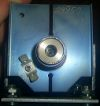
Complete board
GDT primary waveform
Test driver section on a halfbridge
I found a medium sized flyback in the collection, one without screen/focus resistor network. With a 10 turn primary I was going to push its luck :)
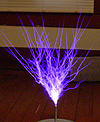
Lovely long sparks that wound ignite from 40mm distance, voltage on the IRFP460 halfbridge is around 140VDC! Such a lovely glow around the core :)
We have just lost cabin pressure! Better find that life jacket under the seat and be ready for this tailspinning crashlanding!
It went okay, until everybody died.
Design PCB for halfbridge section
Its made from components I had available, so C3 and D3 are overrated.
Nice thick traces for the current paths, again, this was done with a tusch by hand.
Etch and assemble halfbridge section PCB
This time I used a large candy box for the etching as the board could no longer fit my tiny etching box, also I made a stronger FeCl3 solution this time, so the etch went alot faster. Turned out almost as I wanted, there are still small spots where the acid goes through the thin tusch drawings, but alot less than earlier etches.
Registered Member #30
Joined: Fri Feb 03 2006, 10:52AM
Location: Glasgow, Scotland
Posts: 6706
Looks good
The reason why everyone does manual duty cycle adjust differently on the TL494, is that it was never really meant to be run open-loop (the duty cycle is always intended to be under feedback control) so the datasheet doesn't give any guidance on how to do it.
There are two basic ways to do it: either use one of the error amps as a follower, or use a pot connected to the deadtime control pin, in the way that the datasheet shows for setting maximum duty cycle. I don't imagine that either of them is particularly accurate, just because the chip was never intended to be used this way, so the designer had no incentive to make it accurate.
Registered Member #1403
Joined: Tue Mar 18 2008, 06:05PM
Location: Denmark, Odense C
Posts: 1968
Steve McConner wrote ...
Looks good
The reason why everyone does manual duty cycle adjust differently on the TL494, is that it was never really meant to be run open-loop (the duty cycle is always intended to be under feedback control) so the datasheet doesn't give any guidance on how to do it.
There are two basic ways to do it: either use one of the error amps as a follower, or use a pot connected to the deadtime control pin, in the way that the datasheet shows for setting maximum duty cycle. I don't imagine that either of them is particularly accurate, just because the chip was never intended to be used this way, so the designer had no incentive to make it accurate.
I never got the potentiometer directly coupled to the dead time control from the reference voltage to work as "liniar" as it does through the error amplifier, on the DTC it would be a very steep logarithmic chance in duty cycle.
Registered Member #51
Joined: Thu Feb 09 2006, 04:17AM
Location:
Posts: 263
Random comment: I bet you could use 10k or so resistors to pull up the output section of the 494 rather than those 2w resistors you are using because the input impedance of the driver chips is very high.
Not that it makes a real difference in operation, it would just make your driver a bit more efficient and dissipate less heat.
Registered Member #1403
Joined: Tue Mar 18 2008, 06:05PM
Location: Denmark, Odense C
Posts: 1968
cjk2 wrote ...
Random comment: I bet you could use 10k or so resistors to pull up the output section of the 494 rather than those 2w resistors you are using because the input impedance of the driver chips is very high.
Not that it makes a real difference in operation, it would just make your driver a bit more efficient and dissipate less heat.
Am I right?
I used the resistors that was used in the test circuit from the datasheet, so I did not give it a deeper thought :)
On a note of the progress, the flyback is currently waiting for the epoxy I filled it with to harden, so the project is on hold for about a week
Registered Member #977
Joined: Thu Aug 30 2007, 06:57PM
Location: England
Posts: 74
Hi, I really like the look of this circuit, I'm thinking about building it with irfp260s to drive a large AC flyback of mine, when you say "modestly powered flyback" what exactly do you mean? And if would this be able to switch about 500 watts of power? I need a about 500 watts out for a CO2 laser power supply. I'm also finding it difficult to find mur1560s cheaply, and in stock, would any ultrafast diode with a voltage rating over 200v and current rating of over 15A do? Because I've found some 200v 16A 35ns recovery diodes for 43p each. Sorry to dig up an old thread but I'm very interested in this circuit, it looks simple and versatile.
Registered Member #1403
Joined: Tue Mar 18 2008, 06:05PM
Location: Denmark, Odense C
Posts: 1968
HDF49 wrote ...
Hi, I really like the look of this circuit, I'm thinking about building it with irfp260s to drive a large AC flyback of mine, when you say "modestly powered flyback" what exactly do you mean? And if would this be able to switch about 500 watts of power? I need a about 500 watts out for a CO2 laser power supply. I'm also finding it difficult to find mur1560s cheaply, and in stock, would any ultrafast diode with a voltage rating over 200v and current rating of over 15A do? Because I've found some 200v 16A 35ns recovery diodes for 43p each. Sorry to dig up an old thread but I'm very interested in this circuit, it looks simple and versatile.
What I meant was with a bridge voltage that does not exceed that transformers voltage/turn ratio, as you can see in the pictures the flyback broke down due to flashover at extreme high voltages.
You basicly adjust the output voltage with your input voltage and the output current with the pulse width. I see no problem for this circuit to deliver your required 500 Watt, it is more of a question which voltage and current you need and then find a transformer that is suitable.
Any diode with similar specifications will work in place of the MUR1560s.
It is a simple circuit, a TL494 driving a halfbridge and thus is very scaleable. Insert a intermediate MOSFET stage to drive large IGBTs etc.
Registered Member #941
Joined: Sun Aug 05 2007, 10:09AM
Location: in a swedish junk pile
Posts: 497
Lots of stray inductance in that DS junction between upper and lower mosfet, as a class d designer, i cringe every time i see mosfets beeing that far apart while beeing operated at 100+ kHz.
This site is powered by e107, which is released under the GNU GPL License. All work on this site, except where otherwise noted, is licensed under a Creative Commons Attribution-ShareAlike 2.5 License. By submitting any information to this site, you agree that anything submitted will be so licensed. Please read our Disclaimer and Policies page for information on your rights and responsibilities regarding this site.


 TL494 flyback driver, walkthrough of design and construction