If you need assistance, please send an email to forum at 4hv dot org. To ensure your email is not marked as spam, please include the phrase "4hv help" in the subject line. You can also find assistance via IRC, at irc.shadowworld.net, room #hvcomm.
Support 4hv.org!
Donate:
4hv.org is hosted on a dedicated server. Unfortunately, this server costs and we rely on the help of site members to keep 4hv.org running. Please consider donating. We will place your name on the thanks list and you'll be helping to keep 4hv.org alive and free for everyone. Members whose names appear in red bold have donated recently. Green bold denotes those who have recently donated to keep the server carbon neutral.
Special Thanks To:
Aaron Holmes
Aaron Wheeler
Adam Horden
Alan Scrimgeour
Andre
Andrew Haynes
Anonymous000
asabase
Austin Weil
barney
Barry
Bert Hickman
Bill Kukowski
Blitzorn
Brandon Paradelas
Bruce Bowling
BubeeMike
Byong Park
Cesiumsponge
Chris F.
Chris Hooper
Corey Worthington
Derek Woodroffe
Dalus
Dan Strother
Daniel Davis
Daniel Uhrenholt
datasheetarchive
Dave Billington
Dave Marshall
David F.
Dennis Rogers
drelectrix
Dr. John Gudenas
Dr. Spark
E.TexasTesla
eastvoltresearch
Eirik Taylor
Erik Dyakov
Erlend^SE
Finn Hammer
Firebug24k
GalliumMan
Gary Peterson
George Slade
GhostNull
Gordon Mcknight
Graham Armitage
Grant
GreySoul
Henry H
IamSmooth
In memory of Leo Powning
Jacob Cash
James Howells
James Pawson
Jeff Greenfield
Jeff Thomas
Jesse Frost
Jim Mitchell
jlr134
Joe Mastroianni
John Forcina
John Oberg
John Willcutt
Jon Newcomb
klugesmith
Leslie Wright
Lutz Hoffman
Mads Barnkob
Martin King
Mats Karlsson
Matt Gibson
Matthew Guidry
mbd
Michael D'Angelo
Mikkel
mileswaldron
mister_rf
Neil Foster
Nick de Smith
Nick Soroka
nicklenorp
Nik
Norman Stanley
Patrick Coleman
Paul Brodie
Paul Jordan
Paul Montgomery
Ped
Peter Krogen
Peter Terren
PhilGood
Richard Feldman
Robert Bush
Royce Bailey
Scott Fusare
Scott Newman
smiffy
Stella
Steven Busic
Steve Conner
Steve Jones
Steve Ward
Sulaiman
Thomas Coyle
Thomas A. Wallace
Thomas W
Timo
Torch
Ulf Jonsson
vasil
Vaxian
vladi mazzilli
wastehl
Weston
William Kim
William N.
William Stehl
Wesley Venis
The aforementioned have contributed financially to the continuing triumph of 4hv.org. They are deserving of my most heartfelt thanks.
Registered Member #2040
Joined: Fri Mar 20 2009, 10:13PM
Location: Fairfax VA
Posts: 180
*Specs, schematic, and construction photos have been added below*
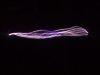
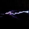
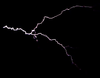
Here are a few pictures of my first DRSSTC. Distance to the target is 43". These are just preliminary photos at about 95VAC into the doubler. The physical dimensions are based on one of Steve's coils, 6" PVC secondary 22" high. The drive circuit is also loosely based on Steve's, primary current feedback, active current control and a huge gdt for the CM300 half-bridge modules. Although I independently designed the drive circuit there are similarities to Steve's so I must give credit where credit is due.
I was looking for 4'-5' with this coil and it appears that I should be able to achieve this fairly easily. Full schematics and pictures at full power will be posted when I have some more time.
Registered Member #639
Joined: Wed Apr 11 2007, 09:09PM
Location: The Netherlands, Herkenbosch
Posts: 512
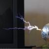
Some very nice strikes If your planning to run it at even higher power I would advice you to use a snubber circuit or tvs on the IGBT's I bit more powerfull diodes for the doubler would also come in handy.
Some more information on the coil would be great too. Those CM-300's should be able to get even longer arcs. I managed 1.8 meters so far with a 1 meter high secondary and a H-bridge of CM-300's running at 350V.
Hope to see some even longer arcs from your coil soon
Registered Member #2040
Joined: Fri Mar 20 2009, 10:13PM
Location: Fairfax VA
Posts: 180
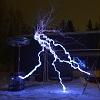
General Max spark length 61" @ 8 RF cycles Operating frequency of 71KHz
Drive Primary current feedback Self tuning Over Current Protection Adjustable duty cyle and break rate
Inverter Full Bridge of two CM300 halfbridge modules Total electrolytic storage capacitance 6000uF Total film bypass capacitance 20uF Tank capacitance 350nF @ 4000VDC (.1uF CDE942's)
Secondary 6" PVC 22" of winding 30 AWG mag wire Stacked toroid of 7" dryer duct on top of 6" dryer duct
Drive circuit theory of operation The cycle begins with the astable timer outputting a short negative pulse, this pulse in turn triggers the monostable timer on the falling portion of the pulse, and then triggers the D-type flip flop clock input on the rising portion of the pulse causing the output to go high. This negative triggering pulse needs to be long enough to give the output of the monostable timer enough time for the output to go high before triggering the flip flop. The high output of the flip folp enables the UCC27324 fet driver, which then drives the mosfets of the discrete full bridge GDT driver, which then drive the CM300 half bridge modules. The 50:1 current transformer is phased to have a negative output on this first RF half cycle. Once the first half of the RF cycle is completed the current in the primary tank circuit continues to flow through the freewheel diodes of the CM300 modules thus driving the output of the 50:1 current transformer high, which drives the UCC FET driver and so forth, this drives the CM300 modules in opposite polarity from the first RF half cycle. When the second RF halfcycle is complete the 50:1 current transformer output goes low, this causes a low to high transition on the clock input of the flip flop, if the data input is high then the output of the flip flop output will remain high and keep the UCC FET drive enabled for an additional full RF cycle. When the data input to the flip flop is low, either from the monostable duty cycle timer, or the monostable over current protection timer overriding the duty cycle timer and pulling the data input low, the flip flop will syncronize the enable signal and the drive signal of the UCC FET driver, preventing mid RF cycle turn off. The overcurrent detection circuit was borrowed from from Steve Ward. It should be noted that the two diode resistor pairs of R1 & D1 and also R2 & D2 form AND gates with the point where Rn & Dn connect being the output.
A quirk of this circuit is that the flip flop needs to be enabled with power going to the inverter. This is because without power to the inverter there will be no current flowing and no feedback via the 50:1 CT, thus no high to low transitions of the CT and no triggering of the flip flop. So what happens is the flip flop gets triggered by the astable timer once where the output goes high, and then stays high due to no low to high transitions on the clock input.
Overall I can say that I am very pleased with the performance of the driver.
Pictures were taken during construction and there have been a few changes since.
Registered Member #2040
Joined: Fri Mar 20 2009, 10:13PM
Location: Fairfax VA
Posts: 180
Why thank you! Too bad it doesn't look like that right now. The whole things a mess right now, I'm working on the final version right now, all the control electronics are going in a 3U rack case.
@ Dalus The bridge is something like 25A @ 600V so I don't think it will need upgrading anytime soon.
This site is powered by e107, which is released under the GNU GPL License. All work on this site, except where otherwise noted, is licensed under a Creative Commons Attribution-ShareAlike 2.5 License. By submitting any information to this site, you agree that anything submitted will be so licensed. Please read our Disclaimer and Policies page for information on your rights and responsibilities regarding this site.


 New Drsstc


 If your planning to run it at even higher power I would advice you to use a snubber circuit or tvs on the IGBT's I bit more powerfull diodes for the doubler would also come in handy.


 .
.