If you need assistance, please send an email to forum at 4hv dot org. To ensure your email is not marked as spam, please include the phrase "4hv help" in the subject line. You can also find assistance via IRC, at irc.shadowworld.net, room #hvcomm.
Support 4hv.org!
Donate:
4hv.org is hosted on a dedicated server. Unfortunately, this server costs and we rely on the help of site members to keep 4hv.org running. Please consider donating. We will place your name on the thanks list and you'll be helping to keep 4hv.org alive and free for everyone. Members whose names appear in red bold have donated recently. Green bold denotes those who have recently donated to keep the server carbon neutral.
Special Thanks To:
Aaron Holmes
Aaron Wheeler
Adam Horden
Alan Scrimgeour
Andre
Andrew Haynes
Anonymous000
asabase
Austin Weil
barney
Barry
Bert Hickman
Bill Kukowski
Blitzorn
Brandon Paradelas
Bruce Bowling
BubeeMike
Byong Park
Cesiumsponge
Chris F.
Chris Hooper
Corey Worthington
Derek Woodroffe
Dalus
Dan Strother
Daniel Davis
Daniel Uhrenholt
datasheetarchive
Dave Billington
Dave Marshall
David F.
Dennis Rogers
drelectrix
Dr. John Gudenas
Dr. Spark
E.TexasTesla
eastvoltresearch
Eirik Taylor
Erik Dyakov
Erlend^SE
Finn Hammer
Firebug24k
GalliumMan
Gary Peterson
George Slade
GhostNull
Gordon Mcknight
Graham Armitage
Grant
GreySoul
Henry H
IamSmooth
In memory of Leo Powning
Jacob Cash
James Howells
James Pawson
Jeff Greenfield
Jeff Thomas
Jesse Frost
Jim Mitchell
jlr134
Joe Mastroianni
John Forcina
John Oberg
John Willcutt
Jon Newcomb
klugesmith
Leslie Wright
Lutz Hoffman
Mads Barnkob
Martin King
Mats Karlsson
Matt Gibson
Matthew Guidry
mbd
Michael D'Angelo
Mikkel
mileswaldron
mister_rf
Neil Foster
Nick de Smith
Nick Soroka
nicklenorp
Nik
Norman Stanley
Patrick Coleman
Paul Brodie
Paul Jordan
Paul Montgomery
Ped
Peter Krogen
Peter Terren
PhilGood
Richard Feldman
Robert Bush
Royce Bailey
Scott Fusare
Scott Newman
smiffy
Stella
Steven Busic
Steve Conner
Steve Jones
Steve Ward
Sulaiman
Thomas Coyle
Thomas A. Wallace
Thomas W
Timo
Torch
Ulf Jonsson
vasil
Vaxian
vladi mazzilli
wastehl
Weston
William Kim
William N.
William Stehl
Wesley Venis
The aforementioned have contributed financially to the continuing triumph of 4hv.org. They are deserving of my most heartfelt thanks.
Registered Member #95
Joined: Thu Feb 09 2006, 04:57PM
Location: Norway
Posts: 1308
After the completion of my PLL Induction heater and reading this thread I became inspired to make another SSTC. I wanted this one to tune itself to exact resonance regardless of delays in the circuit or failure to set potentiometer values correctly. I experimented with phase comparator 1 and 2, along with feedback from a winding under the primary, a small transformer in parallel with the primary, along with conventional antenna and CT feedback. The feedback winding and mini-transformer both gave a signal strong enough to kill the clipping diodes I used, and attempts at weakening the signal would merely distort the waveform. So in the end I used the tried and true antenna and CT feedback. At resonance the secondary voltage will lag the secondary current by 90 degrees, so XOR phase comparator it is. I also implemented a simple discrete driver to weigh up for using UCC's in my previous coil. Risetimes are 100ns to saturation, not bad with 8nF. Oh yeah, fres is 630 kHz.
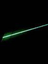
Yesterday I fired up the coil and got first light! I still haven't tuned the primary coil yet, so far the primary current is only 7A RMS which I should be able to double. >:-)
Right now I'm trying to figure out whether or not I should add audio modulation or not. I just bought a keyboard recently and would love to see it modulating the streamers like Steve Conner did. How fast can the inhibit pin on the 4046 react? I'm planning to use a class D style interrupter, which should allow common analogue signals to interrupt the coil and produce music.
Registered Member #89
Joined: Thu Feb 09 2006, 02:40PM
Location: Zadar, Croatia
Posts: 3145
Hey, nice work uzzors.. What is the spark length in those pics? Most I managed from a fullbridge of 450's was about 30cm fullwave rectified sparks with about 7A rms primary current, but with much larger secondary also. I was excessively limited by my idiotic heatsinking though.
but would just like to put out some things I noticed:
After the completion of my PLL Induction heater and reading this thread I became inspired to make another SSTC. I wanted this one to tune itself to exact resonance regardless of delays in the circuit or failure to set potentiometer values correctly. I experimented with phase comparator 1 and 2, along with feedback from a winding under the primary, a small transformer in parallel with the primary, along with conventional antenna and CT feedback. The feedback winding and mini-transformer both gave a signal strong enough to kill the clipping diodes I used, and attempts at weakening the signal would merely distort the waveform. So in the end I used the tried and true antenna and CT feedback.
Ok, I hope we haven't created too much misconceptions here, but what I see here is really weird circuit - congrats for you getting it to work that well!
To cut it short, primary feedback is not possible in SSTC, because of triangular magnetizing current, and period.
At resonance the secondary voltage will lag the secondary current by 90 degrees, so XOR phase comparator it is. I also implemented a simple discrete driver to weigh up for using UCC's in my previous coil. Risetimes are 100ns to saturation, not bad with 8nF. Oh yeah, fres is 630 kHz.
I'm not sure what you tried to accomplish, nor why you used two feedbacks at all?
To me, your CT feedback looks like nothing more than a rube goldberg machine replacing the direct connection between pins 3 and 4.
Second, you need zeners to clamp your feedback - with rail clamping diodes it may happen at some point that your CT supplies more power than your electronics consume, which can cause your +12V rail to rise to dangerous levels and damage components. A single zener with a diode in parallel is usually OK; you need to assure it can handle the dissipation though. Lower voltage zener is better since it handles more current for same dissipation.
third, you didn't do really anything to account for 90 degree phase shift of the xor phase comparator. It is true that secondary voltage is 90 degrees out of phase with current, but you you have no mean of sensing this voltage. Yes, the antenna senses current as well - its not really different from what CT does in your circuit. Proper way to get rid of 90degree shift is to double the frequency and use a flip flop clocked by inverted double-f signal - this can also be useful for implementing dead time later (as COnner did it in his mk 2 driver).
Considering this, to all my understanding biasing the VCO input in your circuit into one side should increase the output somewhat.
If it doesn't, then I have no understanding of this at all and you can safely ignore my entire post
Registered Member #95
Joined: Thu Feb 09 2006, 04:57PM
Location: Norway
Posts: 1308
Thanks. The spark length is appox. 22cm based on the pictures, and bridge heating is nearly non-exsistant (well, you would need a fan for longer runs I assume but it's staying cooler than my 7W gate damping power resistor).
Dr. noob wrote ...
To cut it short, primary feedback is not possible in SSTC, because of triangular magnetizing current, and period.
I'm not sure what you tried to accomplish, nor why you used two feedbacks at all?
Yes, but what I was trying to sense was the inverter's own output voltage with the transformer in parrallel. Before we continue, the point of the whole driver is making a SSTC driver which is 100% self-tuning with no room for human error. And which also makes sense using our theories on how Tesla coils work.
Dr. noob wrote ...
To me, your CT feedback looks like nothing more than a rube goldberg machine replacing the direct connection between pins 3 and 4.
Ahh, the pin 3 and 4 short-cut. I measured the delay from pin 4 to the output voltage from my H-bridge and found it to be 300ns IIRC, at 700kHz that's approaching a 90 degree shift right there. Steve Ward's MKII PLL fixes it by allowing for a user adjustable delay, which has the benefit of allowing adjustment of the phase between the signals too, I think. Since I wanted all user adjustable features out of my driver to ensure a lock EXACTLY on fres I sense the inverter voltage directly. That is through the CT, because at resonance the inverter/primary voltage and inverter current AND the secondary current are all in phase. See where I'm going? A CT makes for a perfect inverter voltage phase feedback when used in a TC.
Dr. noob wrote ...
Second, you need zeners to clamp your feedback - with rail clamping diodes it may happen at some point that your CT supplies more power than your electronics consume, which can cause your +12V rail to rise to dangerous levels and damage components. A single zener with a diode in parallel is usually OK; you need to assure it can handle the dissipation though. Lower voltage zener is better since it handles more current for same dissipation.
Finding fast zeners is a bit of a pain, but most importantly the CT power is rather limited. The current it can supply is the secondary base current (which is low to start with) divided by the turns ratio which results in minuscule currents. I have also used a large filter cap and 7812 regulator for the 12V, which I'll include when I make a new schematic.
Dr. noob wrote ...
third, you didn't do really anything to account for 90 degree phase shift of the xor phase comparator. It is true that secondary voltage is 90 degrees out of phase with current, but you you have no mean of sensing this voltage.
The 90 degree phase shift is the key in the design, see above about inverter output sensing.
Dr. noob wrote ...
Yes, the antenna senses current as well - its not really different from what CT does in your circuit.
This I'm not sure about, logically the antenna should only provide voltage feedback, which it seems to do considering how my circuit works. But then again I don't know everything.
I know it may be desirable to have a means to alter the phase shift by, but that's what the two Steve's PLL drivers are for. Oh, and for eliminating the 90 degree shift wouldn't it be easier to use the type 2 phase comparator?
Oh, and to the question about schematic drawing I use MSpaint, see this thread for the components I use.
Registered Member #1637
Joined: Sat Aug 16 2008, 04:47AM
Location: Kiev, Ukraine
Posts: 83
Cool stuff! I amazed how simly you have got *prfect* tuning with dual feedback )
Just one question - why dont you use shottkeys and ultrafast diodes in your bridge ? Is it quick switch time of bridge's halfs that allows you to ignore slow fet's internal diodes recovery?
Registered Member #95
Joined: Thu Feb 09 2006, 04:57PM
Location: Norway
Posts: 1308
Since the bridge is switching a resonant load it's not much of a problem, but there's still magnetizing current which is hard-switched, so yeah I should maybe include some. The only reason they're not included now is because I don't have any.
Registered Member #1232
Joined: Wed Jan 16 2008, 10:53PM
Location: Doon tha Toon!
Posts: 881
I also am not sure what you are attempting to do with that circuit. If you always want to drive the secondary at resonance, then the two signals fed back to the phase-comparator want to be the inverter output voltage and the secondary top-terminal voltage. These are exactly 90 deg apart at the resonant frequency of the secondary when it is driven from an inverter via link coupling.
An antenna near a working TC can either sense toroid voltage (E-field) or secondary base-current (displacement current from the toroid returning to ground) depending on what impedance the antenna is terminated into. There is a 90 degree phase shift between these two things so this means you have to use a different phase comparator or correct for the phase shift.
I would personally sense inverter output voltage with a VT and secondary base current with a CT and design the PLL to lock with 0 degree seperation between these two variables.
Re the schottky diodes: If the TC secondary is always being driven at resonance, then the inverter will see a net lagging (inductive) load current due to the primary winding inductance in parallel with the TC's reflected load impedance. The MOSFET body diodes will likely suffice for this duty as forced reverse recovery does not take place. The exception to this is if the tuning drifts, or if the TC is run in gated "burst" mode. After each burst of RF energy trapped in the resonator will cause recharging of the bus cap through passive rectification in the MOSFET body-diodes. How well they will hold up to this, I haven't got a clue!
This site is powered by e107, which is released under the GNU GPL License. All work on this site, except where otherwise noted, is licensed under a Creative Commons Attribution-ShareAlike 2.5 License. By submitting any information to this site, you agree that anything submitted will be so licensed. Please read our Disclaimer and Policies page for information on your rights and responsibilities regarding this site.


 My PLL SSTC MKII (fresh new driver)