If you need assistance, please send an email to forum at 4hv dot org. To ensure your email is not marked as spam, please include the phrase "4hv help" in the subject line. You can also find assistance via IRC, at irc.shadowworld.net, room #hvcomm.
Support 4hv.org!
Donate:
4hv.org is hosted on a dedicated server. Unfortunately, this server costs and we rely on the help of site members to keep 4hv.org running. Please consider donating. We will place your name on the thanks list and you'll be helping to keep 4hv.org alive and free for everyone. Members whose names appear in red bold have donated recently. Green bold denotes those who have recently donated to keep the server carbon neutral.
Special Thanks To:
Aaron Holmes
Aaron Wheeler
Adam Horden
Alan Scrimgeour
Andre
Andrew Haynes
Anonymous000
asabase
Austin Weil
barney
Barry
Bert Hickman
Bill Kukowski
Blitzorn
Brandon Paradelas
Bruce Bowling
BubeeMike
Byong Park
Cesiumsponge
Chris F.
Chris Hooper
Corey Worthington
Derek Woodroffe
Dalus
Dan Strother
Daniel Davis
Daniel Uhrenholt
datasheetarchive
Dave Billington
Dave Marshall
David F.
Dennis Rogers
drelectrix
Dr. John Gudenas
Dr. Spark
E.TexasTesla
eastvoltresearch
Eirik Taylor
Erik Dyakov
Erlend^SE
Finn Hammer
Firebug24k
GalliumMan
Gary Peterson
George Slade
GhostNull
Gordon Mcknight
Graham Armitage
Grant
GreySoul
Henry H
IamSmooth
In memory of Leo Powning
Jacob Cash
James Howells
James Pawson
Jeff Greenfield
Jeff Thomas
Jesse Frost
Jim Mitchell
jlr134
Joe Mastroianni
John Forcina
John Oberg
John Willcutt
Jon Newcomb
klugesmith
Leslie Wright
Lutz Hoffman
Mads Barnkob
Martin King
Mats Karlsson
Matt Gibson
Matthew Guidry
mbd
Michael D'Angelo
Mikkel
mileswaldron
mister_rf
Neil Foster
Nick de Smith
Nick Soroka
nicklenorp
Nik
Norman Stanley
Patrick Coleman
Paul Brodie
Paul Jordan
Paul Montgomery
Ped
Peter Krogen
Peter Terren
PhilGood
Richard Feldman
Robert Bush
Royce Bailey
Scott Fusare
Scott Newman
smiffy
Stella
Steven Busic
Steve Conner
Steve Jones
Steve Ward
Sulaiman
Thomas Coyle
Thomas A. Wallace
Thomas W
Timo
Torch
Ulf Jonsson
vasil
Vaxian
vladi mazzilli
wastehl
Weston
William Kim
William N.
William Stehl
Wesley Venis
The aforementioned have contributed financially to the continuing triumph of 4hv.org. They are deserving of my most heartfelt thanks.
Registered Member #325
Joined: Fri Mar 17 2006, 12:42AM
Location: Turku, Finland
Posts: 55
Hi forum,
this is my first post here and I would like to ask for ideas from people more experienced in engineering high voltage contraptions than myself.
Some background: my interest lies mainly in high speed photography of bullets and other fast projectiles (Edgerton style). In order to achieve short enough flash durations, I have given up on using Xenon tubes (with a modified Nikon flash I can almost, but not entirely, freeze a BB pellet). I am now using an open-air spark gap as the light source, which should give me much shorter flash duration (about one microsecond or less is needed for sharp bullets). So basically I'm charging up a capacitor to a high voltage (around 25kV) and when the bullet is in front of the lens, discharging it electronically via a triggered spark gap I built.
Anyway, I am building my own plate stack capacitors for this because I do not want to spend a lot of money on commerical high-voltage pulse capacitors. I have access to an unlimited supply of used overhead transparencies, so I use these as a dielectric. I am not sure about the material, probably mylar. Anyway it seems to have high dielectric strength--I haven't been able to puncture a sheet even with my 80kV marx generator. Thickness is about 0.1-0.15 mm.
I have painstakingly assembled two plate stack capacitors consisting of 100 OH sheets each, interleaved with kitchen aluminum foil and mounted with some iron brackets:
I have not measured the capacitance yet, but guesstimate it to be around 300 nF per cap, depending on the dielectric constant of the material. When charged to around 25kV with a flyback and then discharged, the bang is deafening. With both caps in parallell, the light output is just enough for my photography needs.
Now to my problem: when building the capacitors I used a healthy safey margin of about 10 cm (4 inches) open air distance between plates, thinking that this would stop arc-over. And so it seemed to do at first. However, after a few firings I soon noticed some strange surface tracking along the surface of the dielectricum while the capacitor is being charging. It does not discharge the capacitor immediately, just some thin fractal-like arcs on the surface of the plastic. However, when the voltage rises high enough (maybe around 20kV) there is a spectacular arc-over and the capacitor discharges itself along a 15cm (6 inches) track between the plates , leaving a curious pattern (the photo shows multiple tracks, as each failure seems to dig a new one):
My question is simply: what is causing this and what can be done to prevent it? Is my dielectric breaking down? I do not, however, detect any intensive ozone smell when charging the capacitor, so I don't think corona is an issue. I already searched the web and various forums but could not find anyone having had a similar problem. I have considered (and tried some of) the following options:
Increase distance between plates (this is impractical, and probably not likely to help since some tracks are over 6 inches long)
Clean any possible residue off the sheets. I already tried cleaning them with methanol, but it did not help.
Put everything under oil. I would like to avoid this if at all possible, because of the mess factor.
Make more capacitors and series them. Straightfoward, but work-intensive.
Some sort of high voltage isolating putty, epoxy?
Any other options I have not considered? I am grateful for your hints and explanations. Also if you think this kind of dielectric is inappropriate, I am open to suggestions. I should say that I have also tried 0.2mm polypropylene sheets, which worked wonders for a Tesla tank capacitor at around 2.5kV AC per cap, but also seems to have the same surface tracking problem at higher voltages.
Thanks in advance for any suggestions on how to build a proper plate stack capacitor.
Registered Member #75
Joined: Thu Feb 09 2006, 09:30AM
Location: Montana, USA
Posts: 711
I am not entirey sure if I understand how your capacitor is constructed and where the arcing is occuring, maybe you can post a shot from a different angle?
One thing you could try - a bit messy but much less so than putting the whole capacitor under oil - is to put some vaseline or other grease around the edged of the cap. This is not as permanent as epoxy would be, but should still stop the arcing.
Registered Member #325
Joined: Fri Mar 17 2006, 12:42AM
Location: Turku, Finland
Posts: 55
Hi,
thanks for replying. So, to clarify, the arcs seem to happen randomly in any layer, between the opposite poles and along the surface of the dielectric material. I have drawn a simple figure to illustrate two example points where the arc can occur:
I already put hot melt glue around the edges of one of the caps--however these arcs happen inside the cap, not along the edge so it didn't help. The only thing I achieved was making it much more difficult for me to open it (however I can get if off by baking the cap in the oven). But ideally I would like to avoid all sticky and messy substances.
Registered Member #229
Joined: Tue Feb 21 2006, 07:33PM
Location: Romania
Posts: 506
Your transparencies are written...Isn't the powder conductive? If not, any marks on the sheet surfaces, make discharge points in an intense electric field, though, promoting the discharge.
Registered Member #325
Joined: Fri Mar 17 2006, 12:42AM
Location: Turku, Finland
Posts: 55
I'm pretty sure laser printer/coper toner is nonconductive--in fact it is deposited onto the paper by the copier by statically charging the paper. This pretty much requires the powder particles to be nonconductive so as not to affect neighbouring areas?
Registered Member #229
Joined: Tue Feb 21 2006, 07:33PM
Location: Romania
Posts: 506
Your safety margins can be good for DC voltage, but when the gap is fired you will have a lot of RF current (the discharge is oscillant). Try increasing the safety borders. Do not use the iron barckets, use some plastic pieces to keep together the transparencies. In the building process (did you glued the alu foil on the transparencies, or they just lie one on another?), you can have air trapped between the dielectric and foil. These air traps promote corona, and can form a discharge path. If the dielectric and foil are not glued, just use a thin oil layer on the transparent sheet before aplying the the alu foil. It is not much oil to make a mess (you get the surplus out by pressing the foil), but it will eliminate the air traps.
Registered Member #325
Joined: Fri Mar 17 2006, 12:42AM
Location: Turku, Finland
Posts: 55
vasil wrote ...
Your safety margins can be good for DC voltage, but when the gap is fired you will have a lot of RF current (the discharge is oscillant). Try increasing the safety borders. Do not use the iron barckets, use some plastic pieces to keep together the transparencies. In the building process (did you glued the alu foil on the transparencies, or they just lie one on another?), you can have air trapped between the dielectric and foil. These air traps promote corona, and can form a discharge path. If the dielectric and foil are not glued, just use a thin oil layer on the transparent sheet before aplying the the alu foil. It is not much oil to make a mess (you get the surplus out by pressing the foil), but it will eliminate the air traps.
Thanks for the suggestions. I did not use any glue or oil on the transparancies or foil--they are just stacked on top of each other and clamped together at the ends--so there are definately air pockets in between. However, I did not expect this to be a problem when building them. I will try to remove the brackets and clamp the stacks together tightly to remove air gaps and see if this helps.
BTW, do you think I should expect RF current? I have no inductor in the system, except what you get from wiring and so on. Also the failures do occur while the cap is being charged, not during discharge.
Registered Member #229
Joined: Tue Feb 21 2006, 07:33PM
Location: Romania
Posts: 506
If it is when charging, then is a corona losses matter. Anyway the discharge along an insulator is much longer than in air between electrodes. I think that you have to allow the mess idea. Puting under oil and vacuumating, to remove air is a good idea. 25 kV is a lot of voltage, and there will be a lot of corona in air (breakdown damage). Put it in a sealed container, with no oil leakage and it will keep longer time (but still not too much time, any homemade capacitor has a limited life span).
Registered Member #162
Joined: Mon Feb 13 2006, 10:25AM
Location: United Kingdom
Posts: 3141
Above 10 kV or so is very hard to insulate against surface-tracking if there's humidity I susprct the fault 'grows' as opposed to 'jumps' For a reliable >10 kV single capacitor you need oil. Mylar is much better than pvc but not as good as polythene (polyethylene etc.) for very brief/fast pulses, polypropylene is very good. I expect the film/foil polypropylene capacitors of the type that we use for Tesla Coil MMC would be fast/reliable/cheap/easy.
Registered Member #325
Joined: Fri Mar 17 2006, 12:42AM
Location: Turku, Finland
Posts: 55
Thanks for the information. I had not expected surface tracking to be such a problem, could anyone explain the physics behind this phenomenon or point to some on-line resources? Is it mainly the material properties or air humidity, etc. that affects this? And how do commercial high voltage capacitors avoid this problem?
I suppose I have the following options now:
Decrease the voltage over each capacitor to about 10kV or less, e.g. by seriesing multiple homemade capacitors or building an MMC.
Put everything under oil (messy), and hope for the best.
This site is powered by e107, which is released under the GNU GPL License. All work on this site, except where otherwise noted, is licensed under a Creative Commons Attribution-ShareAlike 2.5 License. By submitting any information to this site, you agree that anything submitted will be so licensed. Please read our Disclaimer and Policies page for information on your rights and responsibilities regarding this site.


 Homemade plate stack capacitor, surface tracking problem
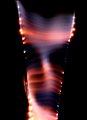

 , leaving a curious pattern (the photo shows multiple tracks, as each failure seems to dig a new one):