If you need assistance, please send an email to forum at 4hv dot org. To ensure your email is not marked as spam, please include the phrase "4hv help" in the subject line. You can also find assistance via IRC, at irc.shadowworld.net, room #hvcomm.
Support 4hv.org!
Donate:
4hv.org is hosted on a dedicated server. Unfortunately, this server costs and we rely on the help of site members to keep 4hv.org running. Please consider donating. We will place your name on the thanks list and you'll be helping to keep 4hv.org alive and free for everyone. Members whose names appear in red bold have donated recently. Green bold denotes those who have recently donated to keep the server carbon neutral.
Special Thanks To:
Aaron Holmes
Aaron Wheeler
Adam Horden
Alan Scrimgeour
Andre
Andrew Haynes
Anonymous000
asabase
Austin Weil
barney
Barry
Bert Hickman
Bill Kukowski
Blitzorn
Brandon Paradelas
Bruce Bowling
BubeeMike
Byong Park
Cesiumsponge
Chris F.
Chris Hooper
Corey Worthington
Derek Woodroffe
Dalus
Dan Strother
Daniel Davis
Daniel Uhrenholt
datasheetarchive
Dave Billington
Dave Marshall
David F.
Dennis Rogers
drelectrix
Dr. John Gudenas
Dr. Spark
E.TexasTesla
eastvoltresearch
Eirik Taylor
Erik Dyakov
Erlend^SE
Finn Hammer
Firebug24k
GalliumMan
Gary Peterson
George Slade
GhostNull
Gordon Mcknight
Graham Armitage
Grant
GreySoul
Henry H
IamSmooth
In memory of Leo Powning
Jacob Cash
James Howells
James Pawson
Jeff Greenfield
Jeff Thomas
Jesse Frost
Jim Mitchell
jlr134
Joe Mastroianni
John Forcina
John Oberg
John Willcutt
Jon Newcomb
klugesmith
Leslie Wright
Lutz Hoffman
Mads Barnkob
Martin King
Mats Karlsson
Matt Gibson
Matthew Guidry
mbd
Michael D'Angelo
Mikkel
mileswaldron
mister_rf
Neil Foster
Nick de Smith
Nick Soroka
nicklenorp
Nik
Norman Stanley
Patrick Coleman
Paul Brodie
Paul Jordan
Paul Montgomery
Ped
Peter Krogen
Peter Terren
PhilGood
Richard Feldman
Robert Bush
Royce Bailey
Scott Fusare
Scott Newman
smiffy
Stella
Steven Busic
Steve Conner
Steve Jones
Steve Ward
Sulaiman
Thomas Coyle
Thomas A. Wallace
Thomas W
Timo
Torch
Ulf Jonsson
vasil
Vaxian
vladi mazzilli
wastehl
Weston
William Kim
William N.
William Stehl
Wesley Venis
The aforementioned have contributed financially to the continuing triumph of 4hv.org. They are deserving of my most heartfelt thanks.
Registered Member #95
Joined: Thu Feb 09 2006, 04:57PM
Location: Norway
Posts: 1308
Just a little something I whipped up over the last few days. I'm not sure if I should be calling it a CW, Greinacher or Villard cascade, but it's a voltage quadrupler at any rate. (seriously, is there a difference? look at the schematics. ) I used 4 strings of sixty RGP10M diodes, and four capacitors made by Mate's recipe. All in all it should be good for about 20kV AC input and 80kV DC at a few kW. All I'm missing now is a decent source of 20kV AC power...
Construction was pretty straight forward. First I made the capacitors with tin foil and overhead transparencies. I made sure to give at least 4cm clearance from the sides so it wouldn't arc over.
Then I moved on to the diode stack. 240 diodes, and they all had to be chained together. It took a few hours from I started until they were all linked together in strings.
Here the diodes are wrapped around a thin PVC pipe to give them some structure and voltage stand-off in a smaller package. Beside them is the pipe they will soon be fitted into.
..and the finished multiplier! Some duct-tape really eases construction.
I can't wait to try it out! I did some early tests with an ignition coil, but 400Hz is too low for 1.3nF caps. It made some sparks though. I'm considering an upgraded ignition coil driver, homemade flyback or the SLR inverter (once I finish it).
Registered Member #1025
Joined: Sun Sept 23 2007, 07:53PM
Location: Czech Rep.
Posts: 566
This reminds me my old doubler project
and a bit my CW project
The ignition coil works very well for this concept, but you need to switch it in KHz frequencies (3-6KHz works the best)
The only thing I do not understand is why your caps have such small capacitance. For 20KV DC you need like two transparencies sheet separtion only (three is already overkill but you can use it to be sure) which should give close to 7nF. Why you use so many transparencies? Remember, one sheet can stand 14KV DC.
And BTW, there is a big difference in quadrupler and two stage CW despite the output voltage is the same. Remeber to put as the lower stage caps with much higher capacitance (twice is minimum)...
Registered Member #95
Joined: Thu Feb 09 2006, 04:57PM
Location: Norway
Posts: 1308
Your multipliers have been a source of inspiration Mates. About your ignition coil driver, what duty cycle do you run it at while doing 6kHz offline?
I still don't see any difference whatsoever between a two stage CW and a voltage quadrupler, am I suffering from some delusion? Is there any non-historical reason that seemingly alike multipliers have different names? At any rate the capacitors need to be rated for 2x Vin, and with some overhead you quickly land around 60kV, which is what the diodes can ideally stand. I used 5 sheets in my capacitors, hence the low capacitance. However, over 10kHz or so they can still supply a few kW of power so the low capacitance isn't much of a hinder.
Registered Member #1025
Joined: Sun Sept 23 2007, 07:53PM
Location: Czech Rep.
Posts: 566
here is a scheme of quadrupler... you see it's a different concept (it gives more power than CW)
Those five sheets - you are right, it's better to be on the safe side... Hope you will not have to deal with side sparking.
My iggy driver is rather special - it's powered straight from the mains (pumping 300V DC into the primary!) and I'm not sure whether you would have any use for that concept (it gives minimum 50KV AC and sucks 600W from the wall). Not every iggy and transistor can stand that... In case you are interested I'll post the scheme...
BTW: I like the idea of the tube in tube design... Only thing is the way you have connected your diodes together - it looks you will have huge corona losses. The joits should be like pearls...Maybe you could solve an oil bath between the walls of those two tubes???...
Registered Member #95
Joined: Thu Feb 09 2006, 04:57PM
Location: Norway
Posts: 1308
I sort of remember what your flyback/ignition coil driver looked like, lots of TVS diodes and heavy IGBTs. Running low duty cycles should be safe though, and with all the primary inductance an ignition coil has the primary current won't rise too high. Do post a schematic though.
I made no attempt at corona suppression because I'm wasn't sure if corona losses would be much of a problem. Do they really drain lots of power? Filling the tube with oil is quite possible, but it would take several liters of oil, and require a redesign. Putting the diodes in a smaller tube, put the capacitors on the outside, then put another tube around the whole setup, and then flood it all with oil. Come to think of it, it wouldn't have taken much extra work if I had thought of it earlier...
Oh, that quadrupler schematic is just a 2 stage CW/Villard/Greinacher fed in the center, a bipolar multiplier of sorts. I see that gives more power without the need for larger capacitors though. Still, the difference is so negligible that I think naming is just a matter of preference.
Registered Member #1025
Joined: Sun Sept 23 2007, 07:53PM
Location: Czech Rep.
Posts: 566
Uzzors wrote ...
I sort of remember what your flyback/ignition coil driver looked like, lots of TVS diodes and heavy IGBTs. Running low duty cycles should be safe though, and with all the primary inductance an ignition coil has the primary current won't rise too high. Do post a schematic though.
Registered Member #1389
Joined: Thu Mar 13 2008, 12:50AM
Location: Pittsburgh, PA
Posts: 346
Mates is right, if you organize the two circuits, a two stage CW Multiplier, and a Quadrupler with the capacitors along the same lines, it becomes apparent that they are not the same circuit, though there are similarities
Registered Member #30
Joined: Fri Feb 03 2006, 10:52AM
Location: Glasgow, Scotland
Posts: 6706
The quadrupler circuit is just two Villard doublers one wired for a positive output, and the other for negative. They have their inputs in parallel and outputs in series.
As far as I know, I introduced this circuit to HV hobbyists when I used it in my Tesla-2 coil It gives more power than a 2-stage C-W multiplier (which is, as someone pointed out, also made of two Villard doublers cascaded) built with the same capacitors.
From Firefox's drawing, it seems that the only difference is one connection. The top right-hand capacitor is fed directly from the transformer in my circuit, whereas it's fed through the top left-hand capacitor in the 2-stage C-W. So maybe the difference in output power isn't that great, although I remember simulating both circuits in PSpice and liking mine more.
Registered Member #95
Joined: Thu Feb 09 2006, 04:57PM
Location: Norway
Posts: 1308
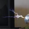
Well, it's complete. And I must say well worth the trouble, despite taking about 6 months to acquire a suitable power supply. With my big-mofo xrfmr in working order I have been able to use this 2-stage CW (I'll surrender to the naming convention to avoid misconceptions) at near maximun rated power. Taking pictures of acrs at their longest is always tough, so I'll let a video do the talking.
A picture of the current setup. I'm running out of table space!
I think the arc had just struck in that picture. As for the sparks, they're created while driving the CW from my homemade xfrmr at 10kV. It was ballasted at the time too, which prevented arc formation unless the leads were brought within close proximity to eachother.
This site is powered by e107, which is released under the GNU GPL License. All work on this site, except where otherwise noted, is licensed under a Creative Commons Attribution-ShareAlike 2.5 License. By submitting any information to this site, you agree that anything submitted will be so licensed. Please read our Disclaimer and Policies page for information on your rights and responsibilities regarding this site.


 80kV CW Tower


 In case you are interested I'll post the scheme...


 And I must say well worth the trouble, despite taking about 6 months to acquire a suitable power supply. With my big-mofo xrfmr in working order I have been able to use this 2-stage CW (I'll surrender to the naming convention to avoid misconceptions) at near maximun rated power. Taking pictures of acrs at their longest is always tough, so I'll let a video do the talking.

