If you need assistance, please send an email to forum at 4hv dot org. To ensure your email is not marked as spam, please include the phrase "4hv help" in the subject line. You can also find assistance via IRC, at irc.shadowworld.net, room #hvcomm.
Support 4hv.org!
Donate:
4hv.org is hosted on a dedicated server. Unfortunately, this server costs and we rely on the help of site members to keep 4hv.org running. Please consider donating. We will place your name on the thanks list and you'll be helping to keep 4hv.org alive and free for everyone. Members whose names appear in red bold have donated recently. Green bold denotes those who have recently donated to keep the server carbon neutral.
Special Thanks To:
Aaron Holmes
Aaron Wheeler
Adam Horden
Alan Scrimgeour
Andre
Andrew Haynes
Anonymous000
asabase
Austin Weil
barney
Barry
Bert Hickman
Bill Kukowski
Blitzorn
Brandon Paradelas
Bruce Bowling
BubeeMike
Byong Park
Cesiumsponge
Chris F.
Chris Hooper
Corey Worthington
Derek Woodroffe
Dalus
Dan Strother
Daniel Davis
Daniel Uhrenholt
datasheetarchive
Dave Billington
Dave Marshall
David F.
Dennis Rogers
drelectrix
Dr. John Gudenas
Dr. Spark
E.TexasTesla
eastvoltresearch
Eirik Taylor
Erik Dyakov
Erlend^SE
Finn Hammer
Firebug24k
GalliumMan
Gary Peterson
George Slade
GhostNull
Gordon Mcknight
Graham Armitage
Grant
GreySoul
Henry H
IamSmooth
In memory of Leo Powning
Jacob Cash
James Howells
James Pawson
Jeff Greenfield
Jeff Thomas
Jesse Frost
Jim Mitchell
jlr134
Joe Mastroianni
John Forcina
John Oberg
John Willcutt
Jon Newcomb
klugesmith
Leslie Wright
Lutz Hoffman
Mads Barnkob
Martin King
Mats Karlsson
Matt Gibson
Matthew Guidry
mbd
Michael D'Angelo
Mikkel
mileswaldron
mister_rf
Neil Foster
Nick de Smith
Nick Soroka
nicklenorp
Nik
Norman Stanley
Patrick Coleman
Paul Brodie
Paul Jordan
Paul Montgomery
Ped
Peter Krogen
Peter Terren
PhilGood
Richard Feldman
Robert Bush
Royce Bailey
Scott Fusare
Scott Newman
smiffy
Stella
Steven Busic
Steve Conner
Steve Jones
Steve Ward
Sulaiman
Thomas Coyle
Thomas A. Wallace
Thomas W
Timo
Torch
Ulf Jonsson
vasil
Vaxian
vladi mazzilli
wastehl
Weston
William Kim
William N.
William Stehl
Wesley Venis
The aforementioned have contributed financially to the continuing triumph of 4hv.org. They are deserving of my most heartfelt thanks.
Registered Member #1408
Joined: Fri Mar 21 2008, 03:49PM
Location: Oracle, AZ
Posts: 679
I need a guiding hand with a question that may seem VERY elementary to many but I would really appreciate any help.....
I have a question I would love to hear varied opinions on......When I see a schematic or wiring diagram with most of the values available, I have heard &/or seen varied methods of making that schematic "live" as a real circuit. I have seen folks spread wires all about a table, some use a breadboard, & others have unique methods that seem to have a "finished" appearance from the very start.
My question deals with the ways people with experience make a schematic function as a finished circuit. I have tried using a breadboard but to my inexperienced mind, they seem too confining and small. I have certainly tried simply spreading wires upon a table to map out the circuit and that seems a very common thing to do. But in so doing I find that I am constantly fighting shorts and the jumble of wires doesn't lead to a clean finished design until I have done the same circuit many times & start to see where the simplifications can be made.
If I were to simply take a schematic and wire it up as it's printed, the finished product seems to waste space and wire. It's generally overly large. People DO put all that into a breadboard but they have a way of conceptualizing that I'm missing - in my inexperience.
Is this simply an issue of experience or is there an engineering technique that allows for a way of thinking that takes a person from schematic to finished product? Thanks for any input or opinion. I know this is a very individual issue but I would love to hear how some of you do this as many of you produce items of a quality SO high that I would love to hear what goes into that final product!
Registered Member #952
Joined: Mon Aug 13 2007, 11:07AM
Location: Finland
Posts: 388
I'm not an expert on making my circuits look high quality, but... When I print out a circuit, I usually take a sheet of paper and make a simple draft of a perf/veroboard layout. Then I assemble the circuit on the board and possibly test it part by part (for example, build the oscillator first, scope it to be sure it's oscillating, then build the power part.)
I try to make the circuit look nice by avoiding too long wires etc. Also one good point: if your project isn't up to board size, then there's no reason making it as small as possible. So if you have space in your project box, feel free to use board space! Often it looks a lot cleaner.
If you do the planning well, you can make even a veroboard layout look very nice! Some people have so much experience that they just throw the parts on the board and solder them together without any planning, and it still looks nice. I would prefer making a layout with just a pencil and an eraser. It's often easier than using any layout design program.
Registered Member #580
Joined: Mon Mar 12 2007, 03:17PM
Location: Melbourne, Australia
Posts: 410
I don't think finished circuits are supposed to be understandable by just looking at it, that is what schematics are for. I often just make a mess on the table with clipleads. for a permanent circuit, i use veroboard and design it with expresspcb, such that underside links run crossways, and all other wires go ontop running in the up/down direction. It it very tiresome and difficult (at least for me) which is one of the main reasons i often don't bother.
Registered Member #1408
Joined: Fri Mar 21 2008, 03:49PM
Location: Oracle, AZ
Posts: 679
Building the oscillator first is a VERY interesting idea! I had heard that a speaker would tone if many transistors were in oscillating; thus short-cutting the concept of completion till other areas were laid out.
I'm hoping that this thread will continue as each person through their successes & failures has unique ideas that may help beginners for years to come. I too use clip leads in Avi's example and had come to find that some frustration can be prevented by circumventing this. Often I've found that my schematic interpretation was just fine but my clip leads were shorting or malfunctioning. Some folks have "tricks" that they enjoy - that speed up the process & almost become a personal style of building.... I only hope that they will share them!
Registered Member #30
Joined: Fri Feb 03 2006, 10:52AM
Location: Glasgow, Scotland
Posts: 6706
Circuits generally look nothing like the schematic, and there is no fixed way of mapping from one to the other. If there was a simple set of rules, I'd be out of a job and so would a lot of other EEs, since we could be replaced by software.
When I was learning, I found it very helpful to study commercial products like TVs and VCRs, by picking broken ones out of dumpsters and trying to fix them without any schematics or service manuals. I found this really difficult at first.
One idea that might help is that the length and shape of the "wires" drawn in a schematic have nothing to do with the layout. The only important things are the nodes: the places where wires join components and each other.
Registered Member #33
Joined: Sat Feb 04 2006, 01:31PM
Location: Norway
Posts: 971
When I make circuits on veroboard, I usually wire them up with magnet wire. The advantage is that you can put all components very tight together and there will still be enough room for the wire.
Magnet wire, if not too thick, is very easy to strip, the enamel usually melts away when you try to solder to it if the iron is hot enough.
My main focus is often to make circuits as compact as possible, so I often end up using SMDs on the underside of the veroboard. This is not too hard when you get the hang of it, and it works wonders to reduce the size of the board.
I've had to make changes to circuits made this way, and it's extremely simple. This is one of the main reasons I prefer this method over etched boards for prototyping and things that need to be finished quickly. For fine-pitched SMD ICs, there's no way around etched boards though, especially if things need to be compact.
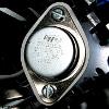
An example of a board I made around a year ago. The underside looks a bit messy, but this was one of my first boards made this way.
Registered Member #95
Joined: Thu Feb 09 2006, 04:57PM
Location: Norway
Posts: 1308
The ability to see a schematic and successfully put it on a breadboard is the probably the largest hinder you'll meet when doing hobby electronics, and simply takes experience to overcome. I remember struggling so much with 555 timer circuits that it took several ties before I got one to work. I even managed to make one release it's magic smoke while following a LED blinking schematic. Eventually you'll get the feel for it though, and it becomes incredibly easy. At least on veroboard, I've never make a PCB before which seems to be a whole different matter.
One thing that helps is understanding how the circuit works, and memorizing it. Knowing component pin outs by heart is a must. I know the 555, TL494 and standard op-amp, transistor and PIC pin outs. Not having to check these really reduces the room for error when testing or building. When actually building a schematic unless it's one I just found on the internet or has a some huge chip in it, I tend to visualize the schematic in my head, and think through the flow of the circuit while building. That way I know if I've missed something, because either the circuit isn't complete or a function is missing. For quick breadboard work always place an IC first, then add support components to it. Building the circuit in modules makes it much easier.
Once you've built the circuit on a breadboard, transferring it to a veroboard (am I getting the names right?) is a peice of cake.
Registered Member #580
Joined: Mon Mar 12 2007, 03:17PM
Location: Melbourne, Australia
Posts: 410
I should add that if you use clipleads, you MUST solder the internal connections inside them! the crimped connection is useless! If you work with high frequencies, you will begin to see the inductance of the leads making your signals look bad, so probably best to consider putting it onto a board at this point.
Registered Member #1107
Joined: Thu Nov 08 2007, 10:09PM
Location:
Posts: 792
When i first started to work with electronics i found it very very hard to get the circut right from a schemattic and it usually took me 6-7 try's to get a 555 working and with a lot of jumpers on top of the breadboard. Now i have it mastered and i can whip up a 555 circut from my head in about 5 min.
Registered Member #56
Joined: Thu Feb 09 2006, 05:02AM
Location: Southern Califorina, USA
Posts: 2445
It all depends on what you are doing...
For quick lashups I will generally put everything I cna in a breadboard, and the other stuff (anything carrying large amounts of current) will be wired together next to the breadboard.
For when I have something simple that I just want done perfboard is the way to go, but the key is to not put wires in the underside, leave them on the top. I find this helps keep the board a lot more usable on the long run. [
But for anything that requires a lot of power, or has a lot of parts in a small aread a pcb is necessary....
This site is powered by e107, which is released under the GNU GPL License. All work on this site, except where otherwise noted, is licensed under a Creative Commons Attribution-ShareAlike 2.5 License. By submitting any information to this site, you agree that anything submitted will be so licensed. Please read our Disclaimer and Policies page for information on your rights and responsibilities regarding this site.


 Conceptualizing: Moving from Schematic / Wiring Diagram; to Finished Circuit