If you need assistance, please send an email to forum at 4hv dot org. To ensure your email is not marked as spam, please include the phrase "4hv help" in the subject line. You can also find assistance via IRC, at irc.shadowworld.net, room #hvcomm.
Support 4hv.org!
Donate:
4hv.org is hosted on a dedicated server. Unfortunately, this server costs and we rely on the help of site members to keep 4hv.org running. Please consider donating. We will place your name on the thanks list and you'll be helping to keep 4hv.org alive and free for everyone. Members whose names appear in red bold have donated recently. Green bold denotes those who have recently donated to keep the server carbon neutral.
Special Thanks To:
Aaron Holmes
Aaron Wheeler
Adam Horden
Alan Scrimgeour
Andre
Andrew Haynes
Anonymous000
asabase
Austin Weil
barney
Barry
Bert Hickman
Bill Kukowski
Blitzorn
Brandon Paradelas
Bruce Bowling
BubeeMike
Byong Park
Cesiumsponge
Chris F.
Chris Hooper
Corey Worthington
Derek Woodroffe
Dalus
Dan Strother
Daniel Davis
Daniel Uhrenholt
datasheetarchive
Dave Billington
Dave Marshall
David F.
Dennis Rogers
drelectrix
Dr. John Gudenas
Dr. Spark
E.TexasTesla
eastvoltresearch
Eirik Taylor
Erik Dyakov
Erlend^SE
Finn Hammer
Firebug24k
GalliumMan
Gary Peterson
George Slade
GhostNull
Gordon Mcknight
Graham Armitage
Grant
GreySoul
Henry H
IamSmooth
In memory of Leo Powning
Jacob Cash
James Howells
James Pawson
Jeff Greenfield
Jeff Thomas
Jesse Frost
Jim Mitchell
jlr134
Joe Mastroianni
John Forcina
John Oberg
John Willcutt
Jon Newcomb
klugesmith
Leslie Wright
Lutz Hoffman
Mads Barnkob
Martin King
Mats Karlsson
Matt Gibson
Matthew Guidry
mbd
Michael D'Angelo
Mikkel
mileswaldron
mister_rf
Neil Foster
Nick de Smith
Nick Soroka
nicklenorp
Nik
Norman Stanley
Patrick Coleman
Paul Brodie
Paul Jordan
Paul Montgomery
Ped
Peter Krogen
Peter Terren
PhilGood
Richard Feldman
Robert Bush
Royce Bailey
Scott Fusare
Scott Newman
smiffy
Stella
Steven Busic
Steve Conner
Steve Jones
Steve Ward
Sulaiman
Thomas Coyle
Thomas A. Wallace
Thomas W
Timo
Torch
Ulf Jonsson
vasil
Vaxian
vladi mazzilli
wastehl
Weston
William Kim
William N.
William Stehl
Wesley Venis
The aforementioned have contributed financially to the continuing triumph of 4hv.org. They are deserving of my most heartfelt thanks.
Registered Member #95
Joined: Thu Feb 09 2006, 04:57PM
Location: Norway
Posts: 1308
I'm about to use the cores I was so lucky to win on ebay a while back, and I thought it would make an decent project thread. So far I've made the transformer and fullbridge (my first!) so most of the fun is already over. I should have posted earlier to create some suspense, but then I guess this project is nothing new. Control electronics will be a garden-variety TL494 driver, maybe with over-current protection. SLR inverters are constant current sources unless I'm mistaken so the over-current protection is useless really, or am I mistaken?
For the fullbridge I'm using IRFP450s for the initial tests, permanently if they hold up. I've never touched an IGBT before but at a first glance they seem to far out-preform mosfets, where's the drawbacks? The transformer is wound with 0.3mm wire, about 250 turns per winding. With 10 primary turns that a step-up of 50, so around 16kV peak from + to -. The windings were actually cut form a secondary I made a long time ago. 0.3mm wire on a 5 cm diameter former doesn't make for a nice fres.
And finally some pictures of my ghetto H-bridge and the biggest ferrite I've every possessed.
Registered Member #1225
Joined: Sat Jan 12 2008, 01:24AM
Location: Beaumont, Texas, USA
Posts: 2253
Sweet! I cannot wait to see this thing run. I loved steve wards so i would like to see new ones. The only drawback i know comparing mosfets to igbts is igbts are MUCH slower than mosfets. I have never owned one but i know the big ones somethimes are 200khz or less(unless i am wrong).
Registered Member #205
Joined: Sat Feb 18 2006, 11:59AM
Location: Skørping, Denmark
Posts: 741
Uhzsaurs wrote ...
0.3mm wire on a 5 cm diameter former doesn't make for a nice fres.
Doesn`t matter.
Fres is determined by the leakage inductance and the series capacitor. Short the secondaries and resonate the tank with a function generator. Monitor peak with scope. From this, calculate the leakage inductance.
With these data, you can calculate power troughput, as a compromise btwn. frequency, leakage inductance and capacitor size.
Registered Member #89
Joined: Thu Feb 09 2006, 02:40PM
Location: Zadar, Croatia
Posts: 3145
Eirik that transformer is a monster, it completely dwarfs the puny bridge of IRFP450's. I don't think you'd be able to get a significant fraction of this core's rated 10+'ish kVA with IRFP 450's.
In your place I'd look for some IGBT modules, 100 amp or so modules and a suitable large heatsink. 1200V devices also have advantage that you could run them from rectified 3 phase supply (which you would definitely need if you want to fully use that core, as it looks to me.).
IGBT's are also proffered in SLR because of high peak currents which occur in capacitor charging due to their relatively constant voltage drop instead of constant resistance.
You could as well parallel a whole bunch of IRFP450 inverters, but I'd really advise against that - it will end in a huge mess, be hard to heatsink, hard to provide separate gate drive to all mosfets and in the end you'll surely regret why haven't you just bought some larger devices.
Look at finn's thread about what he got around. I'm sure he can help you much more...
Doesn`t matter.
Fres is determined by the leakage inductance and the series capacitor. Short the secondaries and resonate the tank with a function generator. Monitor peak with scope. From this, calculate the leakage inductance.
With these data, you can calculate power troughput, as a compromise btwn. frequency, leakage inductance and capacitor size.
Cheers, Finn hammer
Finn, I think he meant that the secondary coils now on the transformer were a part of tesla coil secondary before, which was useless to him as it was wound with too thick wire and had too high Fres. Nothing to do with CCPS.
Registered Member #95
Joined: Thu Feb 09 2006, 04:57PM
Location: Norway
Posts: 1308
Marko wrote ...
Finn, I think he meant that the secondary coils now on the transformer were a part of tesla coil secondary before, which was useless to him as it was wound with too thick wire and had too high Fres. Nothing to do with CCPS.
Right.
I'll buy some IGBTs if I'm sure I can keep them alive, but for now I'll have to do the testing with the hundreds of IRFP450s I have. Their constant voltage drop will really reduce power loss, by at least 75% if I find some good ones.
I finally got everything ready for some real tests today, and I even got some arcs! But before I can take any pictures I need to solve something- I put an over-current shutdown circuit in since I plan to use this inverter for other things later, and with all the mosfets involved it's a good idea anyway. When running from a 50V supply the current waveform looks good, and when the transformer is open circuit the current drops. However when running offline I notice this: The second current spike grows while the first one decreases, this happens as an arc is drawn out. If I leave the transformer open-circuit or without an arc the over-current protection trips. So I assume the current rises high with no load. How do you guys pull arcs with a these things?
2A div, 5µs. Transformer shorted, run from mains. Btw, I am using an external 40µH inductor. It sort of swamps the transformer inductance of 20µH, but that might be good. Why is it that Steve recommends using an external one?
Registered Member #30
Joined: Fri Feb 03 2006, 10:52AM
Location: Glasgow, Scotland
Posts: 6706
Sounds like the higher voltage is making some of your magnetics saturate when you run offline.
Also, have you tried lowering the drive frequency a little and reducing the duty cycle slightly? This might help by making sure that each cycle of resonance is completely finished before the next one starts, so everything will be totally reset with no chance of subharmonic or chaotic effects.
Finn Hammer called the shape of this waveform "buttocks", so I guess what I'm saying is that it's not good for them to be clenched tight together all the time. Doing what I suggested should move them apart and open up a slight period of zero current between them.
The reason why Steve Ward suggested using an external inductor is that it allows a high ratio of magnetizing inductance to leakage inductance. If you start messing with the transformer to add leakage inductance, it can lower the magnetizing inductance too, which brings the danger of unwanted resonances when the secondary is open-circuit.
Registered Member #95
Joined: Thu Feb 09 2006, 04:57PM
Location: Norway
Posts: 1308
Thanks for the tips. I haven't been able to do any actual tests on the transformer over the last two days becasue I was improving the gate drive. Everything looked ok when run without any power applied to the bridge, but with just 50V applied the gates started ringing like crazy. It was so bad that low duty cycles would result in a mess of ~500kHz oscilliations in the linear region, which probably caused problems when running it offline. After some intensive work I fixed it though, and now I can hardly see a difference in the gate waverforms with 50V applied and without.
Now it should be possible to take it under 50% duty, which I doubt I was able to before.
Registered Member #95
Joined: Thu Feb 09 2006, 04:57PM
Location: Norway
Posts: 1308
I rewound the transformer for better coupling, now the primary inductance is 5.5mH with 17.8µH of leakage inductance. I tried playing with different frequencies and duty cycles, but I can't find a point where the waveform looks really good. The closest I get is the "tight" waveform seen earlier. I ran a 25W bulb from the output of the full-bridge, but even with just a sliver of a gate pulse the output still seems around 25%, so maybe I can't get the duty cycle low enough.
Anyway I asked myself, which benefits does SLR have when you just want to pull arcs? Constant current is nice, but good open circuit performance is even nicer. Therefor I'm considering other soft-switching techniques. Are there any that are easy to implement into a full-bridge?
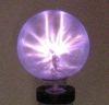
Just to get some arcing action I added a primary side ballast inductor of 40µH, increasing the apparent leakage inductance. The short-circuit current can then be regulated by the swithcing frequency and kept under control. I know it's hard-switched but at least I got to see it arc. I wasn't able to take pictures of the arcs unfortunately, just Lichtenberg figures.
This site is powered by e107, which is released under the GNU GPL License. All work on this site, except where otherwise noted, is licensed under a Creative Commons Attribution-ShareAlike 2.5 License. By submitting any information to this site, you agree that anything submitted will be so licensed. Please read our Disclaimer and Policies page for information on your rights and responsibilities regarding this site.


 Big mo-fo ferrite HV transformer driving (another CCPS/SLR inverter)