 Mosfet and IGBT behaviour difference in resonant inverter design Mosfet and IGBT behaviour difference in resonant inverter design
|
|
|
axizep
|
|
Sat Feb 24 2018, 01:42PM
|

|
|
 Registered Member #61469
Joined: Thu Feb 09 2017, 12:26PM
Location:
Posts: 4
|
Hi dear friends!
I have build a simple half bridge inverter with lc resonant load that would be universal for the tesla coils and induction heater.
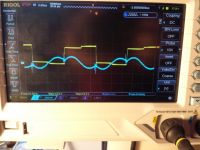
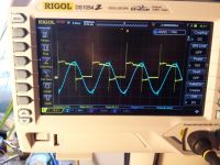
while i was experimenting with construction ive noticed interesting fact: i have observed ringing (which could be a sign of hard switching) of output waveform on my FGH60N60SMD IGBTS when the switching frequency was above resonant frequency of lc tank. when switching freq was under resonant freq there was no observed ringing of wavefor of halfbridge output.
I was very confused with this fact,because i have read many papers about LLC and other resonant inverters that stated: you have to have switching freq above the resonance to have soft switching.
So i have tried to use same driver and same lc tank with mosfet halfbridge.What i have found-that mosfets behave as described in the books: they ring under resonance and have clean waveform above.
i have tried to shun internal intristic diodes of igbts with external shottky's it did reduced ringing by a small amount.
Can someone give me advice on what might be happening here?
I have attached 2 photos IGBT halfbridge output belove and above resonance. Yellow trace is Halbridge output,blue trace is current transformer output.


|
|
Back to top
|
|
|
axizep
|
|
 Registered Member #61469
Joined: Thu Feb 09 2017, 12:26PM
Location:
Posts: 4
|
Please note that all oscillograms where made from 12v 15a power supply on dc bus powering halfbridge.
|
|
Back to top
|
|
Moderator(s): Chris Russell, Noelle, Alex, Tesladownunder, Dave Marshall, Dave Billington, Bjørn, Steve Conner, Wolfram, Kizmo, Mads Barnkob
|
|
Powered by e107 Forum System
|

