If you need assistance, please send an email to forum at 4hv dot org. To ensure your email is not marked as spam, please include the phrase "4hv help" in the subject line. You can also find assistance via IRC, at irc.shadowworld.net, room #hvcomm.
Support 4hv.org!
Donate:
4hv.org is hosted on a dedicated server. Unfortunately, this server costs and we rely on the help of site members to keep 4hv.org running. Please consider donating. We will place your name on the thanks list and you'll be helping to keep 4hv.org alive and free for everyone. Members whose names appear in red bold have donated recently. Green bold denotes those who have recently donated to keep the server carbon neutral.
Special Thanks To:
Aaron Holmes
Aaron Wheeler
Adam Horden
Alan Scrimgeour
Andre
Andrew Haynes
Anonymous000
asabase
Austin Weil
barney
Barry
Bert Hickman
Bill Kukowski
Blitzorn
Brandon Paradelas
Bruce Bowling
BubeeMike
Byong Park
Cesiumsponge
Chris F.
Chris Hooper
Corey Worthington
Derek Woodroffe
Dalus
Dan Strother
Daniel Davis
Daniel Uhrenholt
datasheetarchive
Dave Billington
Dave Marshall
David F.
Dennis Rogers
drelectrix
Dr. John Gudenas
Dr. Spark
E.TexasTesla
eastvoltresearch
Eirik Taylor
Erik Dyakov
Erlend^SE
Finn Hammer
Firebug24k
GalliumMan
Gary Peterson
George Slade
GhostNull
Gordon Mcknight
Graham Armitage
Grant
GreySoul
Henry H
IamSmooth
In memory of Leo Powning
Jacob Cash
James Howells
James Pawson
Jeff Greenfield
Jeff Thomas
Jesse Frost
Jim Mitchell
jlr134
Joe Mastroianni
John Forcina
John Oberg
John Willcutt
Jon Newcomb
klugesmith
Leslie Wright
Lutz Hoffman
Mads Barnkob
Martin King
Mats Karlsson
Matt Gibson
Matthew Guidry
mbd
Michael D'Angelo
Mikkel
mileswaldron
mister_rf
Neil Foster
Nick de Smith
Nick Soroka
nicklenorp
Nik
Norman Stanley
Patrick Coleman
Paul Brodie
Paul Jordan
Paul Montgomery
Ped
Peter Krogen
Peter Terren
PhilGood
Richard Feldman
Robert Bush
Royce Bailey
Scott Fusare
Scott Newman
smiffy
Stella
Steven Busic
Steve Conner
Steve Jones
Steve Ward
Sulaiman
Thomas Coyle
Thomas A. Wallace
Thomas W
Timo
Torch
Ulf Jonsson
vasil
Vaxian
vladi mazzilli
wastehl
Weston
William Kim
William N.
William Stehl
Wesley Venis
The aforementioned have contributed financially to the continuing triumph of 4hv.org. They are deserving of my most heartfelt thanks.
Registered Member #9039
Joined: Wed Dec 26 2012, 03:31PM
Location: Epping, Victoria, Australia
Posts: 117
I am examining the square wave reproduction through various GDTs I am trying.
Square wave straight out of the the 555 through a darlington totem pole - looks like a good square wave to me, apart from a bit of ringing perhaps from the inductor in the LM2756 circuit supplying power to my 555. Frequency is around 10kHz.
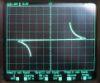
This is what I am seeing on my scope with a square wave going through a GDT made with either an E-core from a small transformer in a PC power unit and also using the core from a tv flyback transformer. I have the square wave going into the primary and my scope GND and probe attached two one of the secondary windings.
Something just aint right here but I don't really understand what is happening here. It does not turn on my FETs at all as far as I can tell.
Can some one explain to me what is happening in the GDT to cause this total distortion of the square wave. It appears that the output pulses are crammed together such that there is only a very brief low time.
I notice that if I increase the frequency to about 30kHz, the wave form coming out of the GDT looks pretty much like this.
When I then decrease the frequency again it appears that those triangular 'cut outs' close up such that you get the wave form in the photo further above.
Registered Member #816
Joined: Sun Jun 03 2007, 07:29PM
Location:
Posts: 156
It looks as if you only got negative going edges, if you only have a single rail supply, did you put an output capacitor in series with the transformer primary? ( largish electrolytic + to the totem pole midpoint if you have the other end of the winding to 0v).
Otherwise verify your totem pole stage is pulling high and low correctly.
Post a sketch of the schematic the way you built it, people may spot something wrong if they can see it.
Registered Member #9039
Joined: Wed Dec 26 2012, 03:31PM
Location: Epping, Victoria, Australia
Posts: 117
Electra wrote ...
It looks as if you only got negative going edges, if you only have a single rail supply, did you put an output capacitor in series with the transformer primary? ( largish electrolytic + to the totem pole midpoint if you have the other end of the winding to 0v).
Otherwise verify your totem pole stage is pulling high and low correctly.
Post a sketch of the schematic the way you built it, people may spot something wrong if they can see it.
I have a 1uF metalised polypropylene cap in series with the GDT primary.
What would you regard as a largish value for an electrolytic capacitor? That can be rather subjective
I will check the wiring on my little totem pole board and get back to you.
Mmmm. It seems that I missed a solder bridge between the base of my NPN to its collector. It is not enough to register with the continuity checker but it must be having an undesirable effect of pulling the NPN high when the 555 output is low.
I'll fix this tomorrow and see how I go.
Edit: After fixing the solder bridge that I missed the waveform coming out of my totem pole circuit is a perfect reproduction of the 555 output.
But the wave form going through the primary of my GDT looks like this:
I have used a N30 toroid as my GDT with 15 primary turns and 30 secondary turns. So what is going wrong here? Too many turns, too few turns?
If I disconnect the GDT then the output of the totem pole is perfect.
[Moderator edit by Mads Barnkob, double posts merged]
Registered Member #9039
Joined: Wed Dec 26 2012, 03:31PM
Location: Epping, Victoria, Australia
Posts: 117
This is quite helpful.
for a single-ended drive circuit (that is, one end is permanently grounded and only the other end is switched, "half-bridge") a turns ratio of 1:2:2 or 1:2.5:2.5 is required. Winding such a transformer properly gets tricky and the output waveform isn't quite convincing, so I wouldn't really recommend the single-ended drive scheme
This is what I have and I guess the lower frequency I am using to energise an ignition coil makes the GDT non-viable in this situation.
So I am going to try making another inverted totem pole, by puting a PNP transistor on the bases, and put the other end of the GDT on the output of this rather than GND.
If that doesn't work then bugger the GDT. I will directly connect the two totem poles to the bases of my FETs and put in some 90V neon bulbs to take the 108V supply down to a level that the darlington transistors can withstand if the FETs ever short out.
Registered Member #33
Joined: Sat Feb 04 2006, 01:31PM
Location: Norway
Posts: 971
You have provided some oscilloscope shots, but not much else. Without a lot of essential information, we can only stumble in the dark and hope to get the right answer. As others have suggested, a schematic of your circuit (not just something similar) is essential. Mark clearly what voltages you have applied, and where the different waveforms are measured. A picture of the circuit is often also very useful for us trying to troubleshoot it. This will take you a bit more time, but it will save you and us a lot of time in trying to solve your problem.
Registered Member #9039
Joined: Wed Dec 26 2012, 03:31PM
Location: Epping, Victoria, Australia
Posts: 117
Wolfram wrote ...
You have provided some oscilloscope shots, but not much else. Without a lot of essential information, we can only stumble in the dark and hope to get the right answer. As others have suggested, a schematic of your circuit (not just something similar) is essential. Mark clearly what voltages you have applied, and where the different waveforms are measured. A picture of the circuit is often also very useful for us trying to troubleshoot it. This will take you a bit more time, but it will save you and us a lot of time in trying to solve your problem.
This is it. The only exception is that I used BDX53C/54C for the totem pole and C was68nF rather than 10nF.The frequency was about 10kHz.
Registered Member #9039
Joined: Wed Dec 26 2012, 03:31PM
Location: Epping, Victoria, Australia
Posts: 117
I am intending to try this variation of the circuit next to see if I can get a better reproduction of the square wave.....based on what I read on the website above.
Registered Member #33460
Joined: Tue Aug 27 2013, 06:23PM
Location: Seattle
Posts: 46
You have your darlingtons configured strangely. I would take the output from both emitters (your PNP is upside down) This will provide the low output impedance needed to quickly charge and discharge C3, which should give you a symmetrical waveform, even under heavy load.
Also, if you haven't already, you really need to put an electrolytic on your supply rail. 500µF might work. 1000µF would be better. Monitor what your supply rail looks like on your oscilloscope when running the circuit under load - it should remain stable.
Registered Member #9039
Joined: Wed Dec 26 2012, 03:31PM
Location: Epping, Victoria, Australia
Posts: 117
Eleccentric wrote ...
You have your darlingtons configured strangely. I would take the output from both emitters (your PNP is upside down) This will provide the low output impedance needed to quickly charge and discharge C3, which should give you a symmetrical waveform, even under heavy load.
Also, if you haven't already, you really need to put an electrolytic on your supply rail. 500µF might work. 1000µF would be better. Monitor what your supply rail looks like on your oscilloscope when running the circuit under load - it should remain stable.
Yeah I forgot to flip them when I inserted them.
This is what I have now:
I am playing around with the resistor values trying to get them right.
I am looking at the Irms and trying get achieve 5mA going through the base of the BC557 and 20mA Irms going through the base of the darlingtons.
Currently I have 2.2k on the base of the BC557 and 150 on the bases of the darlington totem poles.
The larger the value of R1 the large is that small spike is while the BC557 is turned off, although I am trying to make R1 as big as possible so that not to much current flows to GND through it.
Other than compromising on the value of R1 is there any other method to reduce that spike?
Registered Member #9039
Joined: Wed Dec 26 2012, 03:31PM
Location: Epping, Victoria, Australia
Posts: 117
A 555 configured as a not gate work much better in the simulator:
And it avoids the problem where the BC557 is supplied by 15V but the astable 555 output, going into its base, only reaches 14.3V.
The output of the astable 555 is 14.3V and the output of the 555 not gate is 14.3V and you can this as a much more symmetrical waveform coming out of the darlington totem poles.
This site is powered by e107, which is released under the GNU GPL License. All work on this site, except where otherwise noted, is licensed under a Creative Commons Attribution-ShareAlike 2.5 License. By submitting any information to this site, you agree that anything submitted will be so licensed. Please read our Disclaimer and Policies page for information on your rights and responsibilities regarding this site.


 Scope wave form - what does it mean?