If you need assistance, please send an email to forum at 4hv dot org. To ensure your email is not marked as spam, please include the phrase "4hv help" in the subject line. You can also find assistance via IRC, at irc.shadowworld.net, room #hvcomm.
Support 4hv.org!
Donate:
4hv.org is hosted on a dedicated server. Unfortunately, this server costs and we rely on the help of site members to keep 4hv.org running. Please consider donating. We will place your name on the thanks list and you'll be helping to keep 4hv.org alive and free for everyone. Members whose names appear in red bold have donated recently. Green bold denotes those who have recently donated to keep the server carbon neutral.
Special Thanks To:
Aaron Holmes
Aaron Wheeler
Adam Horden
Alan Scrimgeour
Andre
Andrew Haynes
Anonymous000
asabase
Austin Weil
barney
Barry
Bert Hickman
Bill Kukowski
Blitzorn
Brandon Paradelas
Bruce Bowling
BubeeMike
Byong Park
Cesiumsponge
Chris F.
Chris Hooper
Corey Worthington
Derek Woodroffe
Dalus
Dan Strother
Daniel Davis
Daniel Uhrenholt
datasheetarchive
Dave Billington
Dave Marshall
David F.
Dennis Rogers
drelectrix
Dr. John Gudenas
Dr. Spark
E.TexasTesla
eastvoltresearch
Eirik Taylor
Erik Dyakov
Erlend^SE
Finn Hammer
Firebug24k
GalliumMan
Gary Peterson
George Slade
GhostNull
Gordon Mcknight
Graham Armitage
Grant
GreySoul
Henry H
IamSmooth
In memory of Leo Powning
Jacob Cash
James Howells
James Pawson
Jeff Greenfield
Jeff Thomas
Jesse Frost
Jim Mitchell
jlr134
Joe Mastroianni
John Forcina
John Oberg
John Willcutt
Jon Newcomb
klugesmith
Leslie Wright
Lutz Hoffman
Mads Barnkob
Martin King
Mats Karlsson
Matt Gibson
Matthew Guidry
mbd
Michael D'Angelo
Mikkel
mileswaldron
mister_rf
Neil Foster
Nick de Smith
Nick Soroka
nicklenorp
Nik
Norman Stanley
Patrick Coleman
Paul Brodie
Paul Jordan
Paul Montgomery
Ped
Peter Krogen
Peter Terren
PhilGood
Richard Feldman
Robert Bush
Royce Bailey
Scott Fusare
Scott Newman
smiffy
Stella
Steven Busic
Steve Conner
Steve Jones
Steve Ward
Sulaiman
Thomas Coyle
Thomas A. Wallace
Thomas W
Timo
Torch
Ulf Jonsson
vasil
Vaxian
vladi mazzilli
wastehl
Weston
William Kim
William N.
William Stehl
Wesley Venis
The aforementioned have contributed financially to the continuing triumph of 4hv.org. They are deserving of my most heartfelt thanks.
Registered Member #2302
Joined: Sun Aug 16 2009, 04:38PM
Location: Seattle, Washington
Posts: 5
I bought a small "Singing SSTC-Plasma Speaker" kit from Ebay over a year ago, (seller name-Aautomation) and I have finally managed some time to put everything together. I really like everything I have built from this seller and this kit looks great. The coil itself went together quickly and without trouble, however the PSU is giving me some trouble.
The power supply is a 24VAC-4A center-tapped transformer, with (2) bridge rectifiers. One bridge is connected to the whole secondary coil, which should produce about +33V, the other bridge is connected to only the second half of the secondary coil of the transformer, which should produce about half, or +16V. The negative pin of the bridges are connected together to form a "circuit ground". The problem is, when I build this circuit, I actually measure +37VDC on each circuit, after the filter-caps.
I have been contacted by another builder of this same kit, with the same problems. I am not sure if it is something we are reading wrong, or if something was left off the diagram, maybe something more obvious to someone more experienced.
Registered Member #7267
Joined: Tue Oct 16 2012, 12:16AM
Location: Detroit, Michigan
Posts: 407
I have a 24V transformer and necesarry components to make this on a breadboard and compare results to try and find your problem. Is it possible for you to post a pic of your power supply? Specifically the caps and transformer. You might have a bad cap or one in wrong polarity. I will let you know what my findings are after I put this together on breadboard
Registered Member #51
Joined: Thu Feb 09 2006, 04:17AM
Location:
Posts: 263
I am not sure I understand what the problem is. A 24V transformer will produce 40V easily while unloaded. Assuming 25% regulation, 24*sqrt(2)*1.25 = 42.4V. Better use 50V caps!
Edit: I read your post again and it seems that the problem is that you are getting no 16V rail at all. If this is the case then a picture would help.
Registered Member #2302
Joined: Sun Aug 16 2009, 04:38PM
Location: Seattle, Washington
Posts: 5
PJ, Thanks so much for your response. I can take pictures of my circuit in a few hours when I get home, but I really doubt it is a mis-wiring issue. The circuits are very straight forward and not many componets. Also, another builder of the same kit had the exact same problem and was not able to figure it out.
cjk2, You are correct, the 24VAC transformer will put out close to 40V from the entire secondary coil, in this case I measured 37.7V. This is what I need for one power input, so this part of the power supply is working just fine. BTW, I am using 50V rated electrolytic capacitors for the filters. The problem is, the second circuit is wired only through half of the transformer, as it is center-tapped and the intention of this output is to be half of the first circuit, about 18V unloaded. This is the voltage that I need to feed to the 12V regulator on the control board of the SSTC. Unfortuatly, this circuit is also supplying 37.7V, the same as the circuit that is not wired to the center-tap.
I know others have built this kit sucessfully,I have seen pictures of them here on this forum but at least one other builder has had exactly this same problem as I am building this dual voltage power supply.
Registered Member #7267
Joined: Tue Oct 16 2012, 12:16AM
Location: Detroit, Michigan
Posts: 407
Okay so I found one solution to your problem, but I dont know if its the only solution. The problem I found is with the common ground.
Here is with the Negative leads of the bridge rectifier joined together for common ground
As you can see I get roughly 37V from both power outputs, just like you did.
--------
With the Negative leads of the bridge rectifier not joined together
Now I get 37V on one and 18V on the other, which is what it should be, correct?
Sorry, I am not knowledgeable enough to explain why it is this way, but this is just what I found... I would try and contact someone who successfully built this schematic and ask them how they did it, if possible. But in most SSTC's I've seen, the bridge and the logic have their own separate grounds anyways, so I'm kind of confused as to why they are joined here. Somebody else more knowledgeable than I might be able to elaborate on this a bit.
Registered Member #2302
Joined: Sun Aug 16 2009, 04:38PM
Location: Seattle, Washington
Posts: 5
Thanks for all your efforts PJ, I am glad you were able to replicate my results. Of course I still have to figure out how I can power my little coil. I do not have an ground input for each rail on the little PCB.
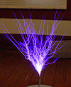
I have taken a couple of pictures, one showing the circuit and a couple more of the coil itself. The circuit is the sloppiest I have ever put together, but I just wanted to test the voltage quickly.
Here is a Youtube video of a working prototype of the kit.[link][/http://www.youtube.com/watch?
v=O3bDFXMx6Ow][]
Registered Member #7267
Joined: Tue Oct 16 2012, 12:16AM
Location: Detroit, Michigan
Posts: 407
Hmm. So I assume then that the circuit board has everything grounded together since the power supply schematic has both rectifiers joined with gnd. I would suggest trying to split the ground as i did (just to see if you can get results) but if your pcb has them joined, it wont make a difference. is that bottom picture where you input your power and gnd?
Registered Member #3414
Joined: Sun Nov 14 2010, 05:05PM
Location: UK
Posts: 4245
You've measured this unloaded, open circuit, right?
Does the same thing happen when both circuits are loaded?
I'm only guessing here. I looked at the circuit until my brain went fuzzy, but I think it might be because the two circuits aren't loaded. Once some current is flowing, you might find things 'sort themselves out'.
Try putting a couple of resistors, or light bulbs, across the outputs, and see what happens
Registered Member #7267
Joined: Tue Oct 16 2012, 12:16AM
Location: Detroit, Michigan
Posts: 407
Ash Small wrote ...
You've measured this unloaded, open circuit, right?
Does the same thing happen when both circuits are loaded?
I'm only guessing here. I looked at the circuit until my brain went fuzzy, but I think it might be because the two circuits aren't loaded. Once some current is flowing, you might find things 'sort themselves out'.
Try putting a couple of resistors, or light bulbs, across the outputs, and see what happens
I was thinking the same thing. When I tested it unloaded with negatives connected together on the rectifier, It output 24V and 12V which is normal, then loaded (but only with the capacitors) it output 37V on both. So I guess your right in that it might be necessary to just feed the 12V regulator with the 37V . That just seems a little much for a little 12v regulator for some reason.
Registered Member #2302
Joined: Sun Aug 16 2009, 04:38PM
Location: Seattle, Washington
Posts: 5
Physics Junkie wrote ...
Hmm. So I assume then that the circuit board has everything grounded together since the power supply schematic has both rectifiers joined with gnd. I would suggest trying to split the ground as i did (just to see if you can get results) but if your pcb has them joined, it wont make a difference. is that bottom picture where you input your power and gnd?
That is correct, there is only a single input for the "ground" on the PCB, which is intended for both circuits.
The bottom picture does show the terminal block where the inputs go. Unfortunately, my kit came with the little pillars glued into the base upside down, which when assembled placed one of the pillars directly in front of the terminal block. I tried to remove one of the pillars from the base, but it broke off the corner of the acrylic base, this made it so I could input the wires, but not so pretty. Once I get everything going properly, I will make a new enclosure which will house the PCB and power supply together.
I am sure someone with more experience could separate the power-supply circuits on the board, but is probably a little over my head right now. I did try separating the grounds on the bridges and just like in your circuit and I had the correct voltages on each circuit, relative to it's own ground, just as you have seen. It would seem the "common-ground" is indeed the issue.
I have attached a copy of the schematic for the coil itself. I hesitate to do this as I do not have the permission of the designer, but I cannot get a hold of him to ask and it is not copyrighted, as far as I can tell. Also, there is not that much to it. If anyone wants me remove the schematic, I will do so immediately.
Ash Small,
I have indeed been checking these circuits open-circuit/without load. I had a lot of hope for this circuit to work properly once it was loaded-down, as you suggested.
I tried to add a load to the outputs. First, I tried a 250 Ohm resistor from each power output to the common ground. This did produce a difference in the resulting voltages, something like +30VDC and +33VDC on the "full-coil" circuit. Next I tried less resistance, a couple of 50 Ohm resistors (10W rated). These increased the difference in the outputs, but only a little more, the "16V circuit" was still producing over 24VDC. I tried a set of 25 Ohm resistors again the differences was bigger, but the 16V supply was still like 25VDC, the 33V supply was reading like 28VDC. Lastly I tried a set of 15 Ohm resistors, but these were only rated for 3W and the resistor across the "33V output" let it's "smoke" out before I could get a reading on them, I guess that much loads needs much more wattage rating.
This may still be the issue, but I would need a better suited load to make absolutely sure, but down to 25 Ohm, the 16V circuit was still putting out over 24VDC. What kind of lightbulbs would be good to use as loads for these circuits?
This site is powered by e107, which is released under the GNU GPL License. All work on this site, except where otherwise noted, is licensed under a Creative Commons Attribution-ShareAlike 2.5 License. By submitting any information to this site, you agree that anything submitted will be so licensed. Please read our Disclaimer and Policies page for information on your rights and responsibilities regarding this site.


 Help needed with "Dual voltage PSU" for Singing Tesla Coil