If you need assistance, please send an email to forum at 4hv dot org. To ensure your email is not marked as spam, please include the phrase "4hv help" in the subject line. You can also find assistance via IRC, at irc.shadowworld.net, room #hvcomm.
Support 4hv.org!
Donate:
4hv.org is hosted on a dedicated server. Unfortunately, this server costs and we rely on the help of site members to keep 4hv.org running. Please consider donating. We will place your name on the thanks list and you'll be helping to keep 4hv.org alive and free for everyone. Members whose names appear in red bold have donated recently. Green bold denotes those who have recently donated to keep the server carbon neutral.
Special Thanks To:
Aaron Holmes
Aaron Wheeler
Adam Horden
Alan Scrimgeour
Andre
Andrew Haynes
Anonymous000
asabase
Austin Weil
barney
Barry
Bert Hickman
Bill Kukowski
Blitzorn
Brandon Paradelas
Bruce Bowling
BubeeMike
Byong Park
Cesiumsponge
Chris F.
Chris Hooper
Corey Worthington
Derek Woodroffe
Dalus
Dan Strother
Daniel Davis
Daniel Uhrenholt
datasheetarchive
Dave Billington
Dave Marshall
David F.
Dennis Rogers
drelectrix
Dr. John Gudenas
Dr. Spark
E.TexasTesla
eastvoltresearch
Eirik Taylor
Erik Dyakov
Erlend^SE
Finn Hammer
Firebug24k
GalliumMan
Gary Peterson
George Slade
GhostNull
Gordon Mcknight
Graham Armitage
Grant
GreySoul
Henry H
IamSmooth
In memory of Leo Powning
Jacob Cash
James Howells
James Pawson
Jeff Greenfield
Jeff Thomas
Jesse Frost
Jim Mitchell
jlr134
Joe Mastroianni
John Forcina
John Oberg
John Willcutt
Jon Newcomb
klugesmith
Leslie Wright
Lutz Hoffman
Mads Barnkob
Martin King
Mats Karlsson
Matt Gibson
Matthew Guidry
mbd
Michael D'Angelo
Mikkel
mileswaldron
mister_rf
Neil Foster
Nick de Smith
Nick Soroka
nicklenorp
Nik
Norman Stanley
Patrick Coleman
Paul Brodie
Paul Jordan
Paul Montgomery
Ped
Peter Krogen
Peter Terren
PhilGood
Richard Feldman
Robert Bush
Royce Bailey
Scott Fusare
Scott Newman
smiffy
Stella
Steven Busic
Steve Conner
Steve Jones
Steve Ward
Sulaiman
Thomas Coyle
Thomas A. Wallace
Thomas W
Timo
Torch
Ulf Jonsson
vasil
Vaxian
vladi mazzilli
wastehl
Weston
William Kim
William N.
William Stehl
Wesley Venis
The aforementioned have contributed financially to the continuing triumph of 4hv.org. They are deserving of my most heartfelt thanks.
Registered Member #4460
Joined: Sat Apr 07 2012, 08:31AM
Location:
Posts: 9
I saw someone on youtube put a capacitor across the primary of their flyback which was powered by a 555 driver. I tried the same thing on my TL494 full bridge flyback driver which I built from the schematic on scopeboy's site and I got excellent results with a .15 uf capacitor. It stopped working after a while though and I hooked it up to the scope to see that my my TC4429 was not outputting a signal any longer and was also getting hot enough to burn me. I was using 12v to power the logic and a separate 24v 16a supply for the mosfets so I was driving the circuit terribly hard. My question is, will that capacitor across the primary ruin my inverter? Or is something else wrong? I don't really want to burn up another TC4429 until I figure out whats going on. I would appreciate anyone's insight!
Registered Member #543
Joined: Tue Feb 20 2007, 04:26PM
Location: UK
Posts: 4992
The addition of the capacitor has turned the primary into a parallel resonant tuned circuit, across which a high potential difference will appear will appear when it is close to resonance.
Registered Member #9252
Joined: Fri Jan 04 2013, 06:27AM
Location: Andromeda
Posts: 253
I have had such a exp but with a cfl.. I just take the the cfl output wires that goes into the tube. put a ceramic cap on the 2 output wires and into the original flyback primary coil. = more than 15 times long arcs than with no cap
Just don't do what i just said. once you take away the hv- wire away from the red wire the cfl goes boom and the house circuit breaker goes off. so be careful tho maybe if you heat sink the transistors on a 110 watt cfl. it would live longer. also it's better to have the fbt under oil and the hv -ve grounded if you plan on doing that. i noticed the cfl lives much longer that way. :)
Registered Member #4460
Joined: Sat Apr 07 2012, 08:31AM
Location:
Posts: 9
Proud Mary wrote ...
The addition of the capacitor has turned the primary into a parallel resonant tuned circuit, across which a high potential difference will appear will appear when it is close to resonance.
Ok that makes sense. What I still cant figure out though is how my TC4429 got toasted, since it only connects to the mosfet gates, its not connected to the primary at all
Registered Member #543
Joined: Tue Feb 20 2007, 04:26PM
Location: UK
Posts: 4992
Circuit diagrams often fool us into thinking that electricity flows from left to right, or that electrons will always flow following the lines on the paper. Voltage spikes in particular can do things like travel back up wires and wreck your power supply, or induce currents in neighbouring wires where they are not wanted, and so on, Of course, we can't be sure that this is what did for your chip, but if you get a high AC voltage appearing in one place, and something fizzles out nearby, the possibility should be checked. Is the supply line adequately decoupled, so that rogue spikes get by-passed to Earth, rather than getting coupled into every circuit hanging from the supply rail?
Registered Member #4460
Joined: Sat Apr 07 2012, 08:31AM
Location:
Posts: 9
Proud Mary wrote ...
Is the supply line adequately decoupled, so that rogue spikes get by-passed to Earth, rather than getting coupled into every circuit hanging from the supply rail?
I'm not sure I fully understand the question, but if your refering to the layout, then yes, it could definitely use some work as far as the logic being close to the traces for the primary winding and the drain/source on the mosfets.
I'm also thinking maybe my primary had too few turns (only 6) I switched to a flyback with 10 turns on the primary and so far I haven't burnt another chip
Registered Member #3414
Joined: Sun Nov 14 2010, 05:05PM
Location: UK
Posts: 4245
cjanik wrote ...
I'm also thinking maybe my primary had too few turns (only 6) I switched to a flyback with 10 turns on the primary and so far I haven't burnt another chip
increasing the number of turns on the primary will do two things, as far as I'm aware. Firstly, it will decrease voltage on the secondary, secondly, if the circuit was at resonance with six turns, it will put the circuit 'out of resonance'.
I imagine it's the second that is causing your IC not to burn. What is the arc like compared to before, when the IC burned?
Registered Member #4460
Joined: Sat Apr 07 2012, 08:31AM
Location:
Posts: 9
Ash Small wrote ...
cjanik wrote ...
I'm also thinking maybe my primary had too few turns (only 6) I switched to a flyback with 10 turns on the primary and so far I haven't burnt another chip
increasing the number of turns on the primary will do two things, as far as I'm aware. Firstly, it will decrease voltage on the secondary, secondly, if the circuit was at resonance with six turns, it will put the circuit 'out of resonance'.
I imagine it's the second that is causing your IC not to burn. What is the arc like compared to before, when the IC burned?
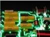
Hot, white, and fat. I know changing the number of primary turns will affect the resonant frequency. I readjusted the frequency for optimal arcs again and they're not as intense as before, which is what I expected. Hopefully the smaller arcs don't stress the IC as much.
Registered Member #543
Joined: Tue Feb 20 2007, 04:26PM
Location: UK
Posts: 4992
cjanik wrote ...
Proud Mary wrote ...
Is the supply line adequately decoupled, so that rogue spikes get by-passed to Earth, rather than getting coupled into every circuit hanging from the supply rail?
I'm not sure I fully understand the question, but if your refering to the layout, then yes, it could definitely use some work as far as the logic being close to the traces for the primary winding and the drain/source on the mosfets.
Read the Wikipedia entry for decoupling capacitor.
Registered Member #834
Joined: Tue Jun 12 2007, 10:57PM
Location: Brazil
Posts: 644
The use of this capacitor is as old as induction coils with mechanical switches, and a totally correct idea. Without it the pulse that appears over the switching element is only limited by breakdown of the device, and will destroy a transistor without protection very easily. But with a capacitor, the voltage over the transistor first rises to a limited level and then falls, as the capacitor resonates with the coil, and tries to go below the ground line. If a bipolar transistor is being used, the base-collector junction will be forward-biased and a large current will flow from the driving circuit, possibly destroying it. The solution is to add a fast high-voltage diode across the transistor. This can be seen in most schematic diagrams of CRT TVs and monitors, and the required elements can be obtained from the same boards from where these flyback transformers can be salvaged (along with all the driving circuit and a complete switching power supply, if you want).
This site is powered by e107, which is released under the GNU GPL License. All work on this site, except where otherwise noted, is licensed under a Creative Commons Attribution-ShareAlike 2.5 License. By submitting any information to this site, you agree that anything submitted will be so licensed. Please read our Disclaimer and Policies page for information on your rights and responsibilities regarding this site.


 Capacitor across flyback primary