If you need assistance, please send an email to forum at 4hv dot org. To ensure your email is not marked as spam, please include the phrase "4hv help" in the subject line. You can also find assistance via IRC, at irc.shadowworld.net, room #hvcomm.
Support 4hv.org!
Donate:
4hv.org is hosted on a dedicated server. Unfortunately, this server costs and we rely on the help of site members to keep 4hv.org running. Please consider donating. We will place your name on the thanks list and you'll be helping to keep 4hv.org alive and free for everyone. Members whose names appear in red bold have donated recently. Green bold denotes those who have recently donated to keep the server carbon neutral.
Special Thanks To:
Aaron Holmes
Aaron Wheeler
Adam Horden
Alan Scrimgeour
Andre
Andrew Haynes
Anonymous000
asabase
Austin Weil
barney
Barry
Bert Hickman
Bill Kukowski
Blitzorn
Brandon Paradelas
Bruce Bowling
BubeeMike
Byong Park
Cesiumsponge
Chris F.
Chris Hooper
Corey Worthington
Derek Woodroffe
Dalus
Dan Strother
Daniel Davis
Daniel Uhrenholt
datasheetarchive
Dave Billington
Dave Marshall
David F.
Dennis Rogers
drelectrix
Dr. John Gudenas
Dr. Spark
E.TexasTesla
eastvoltresearch
Eirik Taylor
Erik Dyakov
Erlend^SE
Finn Hammer
Firebug24k
GalliumMan
Gary Peterson
George Slade
GhostNull
Gordon Mcknight
Graham Armitage
Grant
GreySoul
Henry H
IamSmooth
In memory of Leo Powning
Jacob Cash
James Howells
James Pawson
Jeff Greenfield
Jeff Thomas
Jesse Frost
Jim Mitchell
jlr134
Joe Mastroianni
John Forcina
John Oberg
John Willcutt
Jon Newcomb
klugesmith
Leslie Wright
Lutz Hoffman
Mads Barnkob
Martin King
Mats Karlsson
Matt Gibson
Matthew Guidry
mbd
Michael D'Angelo
Mikkel
mileswaldron
mister_rf
Neil Foster
Nick de Smith
Nick Soroka
nicklenorp
Nik
Norman Stanley
Patrick Coleman
Paul Brodie
Paul Jordan
Paul Montgomery
Ped
Peter Krogen
Peter Terren
PhilGood
Richard Feldman
Robert Bush
Royce Bailey
Scott Fusare
Scott Newman
smiffy
Stella
Steven Busic
Steve Conner
Steve Jones
Steve Ward
Sulaiman
Thomas Coyle
Thomas A. Wallace
Thomas W
Timo
Torch
Ulf Jonsson
vasil
Vaxian
vladi mazzilli
wastehl
Weston
William Kim
William N.
William Stehl
Wesley Venis
The aforementioned have contributed financially to the continuing triumph of 4hv.org. They are deserving of my most heartfelt thanks.
Registered Member #1451
Joined: Wed Apr 23 2008, 03:48AM
Location: Boulder, Co
Posts: 661
This thread will follow the build of my new coilgun. It's going to have the following specs: 4 Stage, coils are around 36 uH 14awg. Four layers, 32 mm long 4 x 320 uF 1200V polypropylene caps 4 x 1200V 3.5kA pulse stud SCRs CCPS to charge everything up quite fast hopefully. Brass projectile with wall thickness equal to skin depth Capacitive sensing of the projectile PVC coil form
The gun will be an inductance type. Each coil is designed as to have around 3kA peak staying within the SCRs' limits. When the projectile reaches a certain point past the coil, the coil will fire inducing eddy currents and pushing the projectile forwards. I'm using a capacative system to sense where the projectile is. I'll use this to alter the position of the projectile when the coil fires to figure out best efficiency. The four coils will be wound on a pvc coil form. The form itself is actually two pieces bolted together as the bore length was too long to have a single piece.
As far as the capacitive sensing, this is my setup. I have aluminum foil wrapped under the coil to be the first plate. There is a second section of foil immediately following the coil. The projectile will bridge the gap between them and increase the capacitance of the circuit. I'm thinking that I'll have an oscillator circuit that will change frequency as the capacitance changes. I'll read the frequency with a micro and use that to switch the coils. Does this sound feasible? We'll see what happens.
Below are the pictures of the first section of coil form, the capacitor plates, and the first coil wound on.
Machined the other part of the barrel today. It bolts together with four M3 machine screws and everything lines up great! The projectile falls through the barrel fine but it you plug one end it slows way down due to the good fit.
I also found that if I run a 12V 7kHz signal through the capacitive sensor, the signal that gets through goes from 1.8V to 3.6V! That should be plenty to trigger on and also allow some room to detect position.
I think I'll have a small daughterboard above each of the coils that will have the signal generator and amplifier. I think I'll have a dual op amp setup so that the output of another sensor is subtracted from the output of the current sensor. In other words, since all sensors are identical and the projectile can only be in one sensor at a time, there will always be two waveforms being compared, one with the projectile and one without. If this makes no sense I can answer any questions.
Below is a quick paint diagram showing the schematic and physical layout of the capacitive sensor.
And then the new barrel section attached and also with a closeup.
Here is the schematic I worked up for the capacitive sensors. It uses a differential amp for each section fed into the ADC of a PIC16F690. The connector going into the amps will have one feed from the section being triggered and one feed from a different section for use as a baseline measurement. I'll generate the frequency train with the PIC. The PIC 16F690 will then monitor the charge on the capacitors and all other functions. I think I'll have a slave micro running the cap charger and possible magazine power supply. Would there be any benefit in using a dedicated charger for each capacitor? The total power input would be the same but would the charging time increase? Below is the schematic.
EDIT** I have now changed the schematics, see below for the updated design.
I wound the rest of the coils tonight. I'm home now for a bit and have access to a good camera so the pics should be better quality .
SCHEMATICS AND BOARD
Here is the updated circuitry. I am now using a PIC16F887 just because I have it on hand. I'm using a module system similar to that of the Arduino/Shield deal. Each board will plug into the main control board with exception of the charging board witch will be mounted on the heat sink. I have also added connections on the control board for an 16X2 line LCD display.
The connectors provide a 5V, 12V, and gnd power connection. They also have all of the unused in/outs of the micro. This will allow any other daughter boards to be connected if the need arises, which most likely will!
Registered Member #1451
Joined: Wed Apr 23 2008, 03:48AM
Location: Boulder, Co
Posts: 661
You do, but you also get a stronger magnetic field with more current, That wire will have close to 3,000 amps flowing through it so it needs to be thick.
Registered Member #1451
Joined: Wed Apr 23 2008, 03:48AM
Location: Boulder, Co
Posts: 661
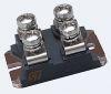
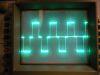
I have now gone from design of the boards to experimentation. I have etched the CCPS board and partially populated it. I'm using a PIC12F617 to generate the pulse chain and monitor the cap's voltage. As I etched the board before changing the part I'm not making use of the PWM module of the chip. Instead, I've just written a program that bit bangs a serial input from the main control micro and then runs a loop of fixed number of pulses. After the loop, the cap voltage is checked and another loop of pulses is run if needed. The serial interface lets the micros know what voltage the capacitors are to be charged to and when they are full. Below are some pics of the heat sink that will be used and the CCPS board with everything but the high side passive components. Also, a couple waveforms in there too.
The Inductor to insure proper oscillations of the tank circuit.
Registered Member #1451
Joined: Wed Apr 23 2008, 03:48AM
Location: Boulder, Co
Posts: 661
Thanks!
It would seem so but the foil tape actually has an insulating layer; the adhesive. This means that when the edges overlap they are not actually electrically connected. I don't know if it shorted on the edges but I suppose I'll find out when I start testing!
Registered Member #1451
Joined: Wed Apr 23 2008, 03:48AM
Location: Boulder, Co
Posts: 661
I've started working on the brains of the operation. This is my first time working with an LCD and also programming in C. I've found a great enclosure for the electronics! It was an old computer controlled CD changer. It has a separate SMPS board in the back with line filtering and 5V and 12V lines. It will house the digital electronics and the inverter. The caps will be mounted on top with the coilgun and scr's on top of those. I've found a lot of 1/2" and 3/8" plexi so most of the mechanical structure will be of that.
The coilgun will be controlled through an 8 button switch panel. The LCD will allow the cap charge, rate of fire, and number of shots to be altered through a menu setup. The main control board will handle all of this apart from actual charging which is handled by the SLR micro. The control micro sends out a set of commands and the SLR one charges the caps to the set voltage and returns a done command to the control. I've already taken care of the serial transmit functions in the programs. Next I'm going to breadboard the capacitive sensors to make sure they work.
And of course the pictures:
The Full case
LCD in the dark. You can kinda see the board under it.
An over all of the control bread board. The input board can be seen on the right. Each input has an individual 47K pull-up resistor.
Registered Member #1451
Joined: Wed Apr 23 2008, 03:48AM
Location: Boulder, Co
Posts: 661
I haven't been working on this project in a while, but decided that I need to get back to it. So first thing I do is hook up a quick scr + trigger+ all-that-other-stuff to test it out. Charge up to a measly 160V and fire. I hear a click but nothing else. So I hook up a doubler and charge up to 350V and try again. This time a click and the projectile moves only a tiny fraction of an inch. Apparently it doesn't work how I thought it would. After playing around in FEMM and doing some thinking, I realized that no matter what, due to Lorentz Law, the force will always be pushing in on the projectile and not from the back like I thought. This is because for the most part, the flux lines will be traveling radially down the projectile. For the gun to work, the flux lines would have to be traveling from the center of the projectile out to the coil so that the force vector is correct. After a lot of thought, I cam up with an idea. I would run an iron rod down the middle of the barrel with the projectile slid over the top. This would mean that the field lines would hopefully be in the correct position at the ends of the coils. When simulating this, it seems like it will work wonderfully! The projectile has a 45N force acting on it at the highest current, the same that an iron projectile would experience! Below are a couple screen shots with this new set up. The first one is with the first coil energized and the second one is with the next coil. I found the highest force to be achieved with the center of the projectile about at the end of the coil. With this set up, the projectile actually has a large force on it anywhere past the center position of the coil.
EDIT: It seems like the number I provided for force should only be used as a qualitative estimate. That number was with a planar calculation with a depth of 1mm. With a depth of 10mm (1/2 the diameter of my coils) the force is multiplied by ten. When I changed the simulation to axisymetric, the total force was 139N which seems much more realistic to me!
The first stage:
The second stage:
I have got the communication working between the main micro and the CCPS control micro. It was a pain figuring out how to do it with the very limited feature set that the 12f pic has. None the less, it receives and interprets commands and can respond to them.
I have also decided to do away with the capacitive sensor and go with traditional optical sensors as they are very reliable. I have drilled all the holes and have the parts already in my bin, do now I can devote most of the work to get the thing actually firing!
This site is powered by e107, which is released under the GNU GPL License. All work on this site, except where otherwise noted, is licensed under a Creative Commons Attribution-ShareAlike 2.5 License. By submitting any information to this site, you agree that anything submitted will be so licensed. Please read our Disclaimer and Policies page for information on your rights and responsibilities regarding this site.


 Four Stage Inductance Coilgun


 .
.