If you need assistance, please send an email to forum at 4hv dot org. To ensure your email is not marked as spam, please include the phrase "4hv help" in the subject line. You can also find assistance via IRC, at irc.shadowworld.net, room #hvcomm.
Support 4hv.org!
Donate:
4hv.org is hosted on a dedicated server. Unfortunately, this server costs and we rely on the help of site members to keep 4hv.org running. Please consider donating. We will place your name on the thanks list and you'll be helping to keep 4hv.org alive and free for everyone. Members whose names appear in red bold have donated recently. Green bold denotes those who have recently donated to keep the server carbon neutral.
Special Thanks To:
Aaron Holmes
Aaron Wheeler
Adam Horden
Alan Scrimgeour
Andre
Andrew Haynes
Anonymous000
asabase
Austin Weil
barney
Barry
Bert Hickman
Bill Kukowski
Blitzorn
Brandon Paradelas
Bruce Bowling
BubeeMike
Byong Park
Cesiumsponge
Chris F.
Chris Hooper
Corey Worthington
Derek Woodroffe
Dalus
Dan Strother
Daniel Davis
Daniel Uhrenholt
datasheetarchive
Dave Billington
Dave Marshall
David F.
Dennis Rogers
drelectrix
Dr. John Gudenas
Dr. Spark
E.TexasTesla
eastvoltresearch
Eirik Taylor
Erik Dyakov
Erlend^SE
Finn Hammer
Firebug24k
GalliumMan
Gary Peterson
George Slade
GhostNull
Gordon Mcknight
Graham Armitage
Grant
GreySoul
Henry H
IamSmooth
In memory of Leo Powning
Jacob Cash
James Howells
James Pawson
Jeff Greenfield
Jeff Thomas
Jesse Frost
Jim Mitchell
jlr134
Joe Mastroianni
John Forcina
John Oberg
John Willcutt
Jon Newcomb
klugesmith
Leslie Wright
Lutz Hoffman
Mads Barnkob
Martin King
Mats Karlsson
Matt Gibson
Matthew Guidry
mbd
Michael D'Angelo
Mikkel
mileswaldron
mister_rf
Neil Foster
Nick de Smith
Nick Soroka
nicklenorp
Nik
Norman Stanley
Patrick Coleman
Paul Brodie
Paul Jordan
Paul Montgomery
Ped
Peter Krogen
Peter Terren
PhilGood
Richard Feldman
Robert Bush
Royce Bailey
Scott Fusare
Scott Newman
smiffy
Stella
Steven Busic
Steve Conner
Steve Jones
Steve Ward
Sulaiman
Thomas Coyle
Thomas A. Wallace
Thomas W
Timo
Torch
Ulf Jonsson
vasil
Vaxian
vladi mazzilli
wastehl
Weston
William Kim
William N.
William Stehl
Wesley Venis
The aforementioned have contributed financially to the continuing triumph of 4hv.org. They are deserving of my most heartfelt thanks.
Registered Member #95
Joined: Thu Feb 09 2006, 04:57PM
Location: Norway
Posts: 1308
While visiting my grandparents I found some old tubes in a box which used to belong to my grandfather. Apparently they were part of an old "Radionette" radio, which is now long gone. I thought it would be pretty cool to recycle the tubes by using them in an audio amplifier. The tubes I found are 5Y3GT, 7C5, 7R7, ECH21 and what I assume is "EH2", but the name is almost worn off. The tubes seem ok, except the ECH21 which has a bent pin with cracked glass at the pin. The "EH22" has the same serial number on it from Radionette, so I'm assuming it was meant as a replacement. After some research I see the 5Y3GT is a fullwave rectifier and the 7C5 is a decent beam amplifier. I can't find much info on the other tubes, other than that they seem to contain a combo of either diode/pentode/triode based on various web searches. I think I can use the 5Y3GT and 7C5 without much difficulty, but I would like to use one of the other tubes as a preamp for the 7C5. This will be an amplifier for mp3 players or laptops. Now the question is which tube, and how do I set it up as a triode? The choice is between using the 7R7 or the "EH2" (ECH21 equiv I think).
Also, the tubes might be 60 years old for all I know. Is there anything I can/should do prior to using them besides washing?
Registered Member #543
Joined: Tue Feb 20 2007, 04:26PM
Location: UK
Posts: 4992
I think you are right to guess that some of the part number is missing from the valve EH2**.
ECH81 is a triode-heptode frequency changer, and the valve actually called "EH2" is also a heptode frequency changer (usually run as a self-oscillating mixer)
It seems to me very unlikely that a simple domestic receiver like your grandfather's would have had two frequency changers of anytype (even if the receiver had VHF/UKW, a heptode would not be the valve to choose as self-oscillating mixer at this frequency)
So look inside your mystery "EH2??" valve with a strong light and see if you can see how many grids it has. I will guess that it is the RF pentode that preceeded the frequency changer, which would be the normal arrangement in a simple consumer radio like this.
I would guess the original line up had been something like this:
mystery valve (RF amplifier - almost certainly a pentode)
ECH81 (triode section: local oscillator, heptode section: mixer)
7R7 (D1: detector D2: AGC diode; pentode section: First AF)
7C5 audio output (equivalent to 6V6)
5Y3-GT as full-wave HT rectifier (originally working from a centre-tapped transformer)
Registered Member #95
Joined: Thu Feb 09 2006, 04:57PM
Location: Norway
Posts: 1308
The mystery valve is the 164884 one with the screen on the inside in the picture above. I'm not sure what to look for, but I'm sure your guess is correct. I've made a preliminary schematic, mind you this is the first time I've worked with tubes so there may be some grave mistakes. (Which I hope will be pointed out!) I based the design on the suggested schematics found along with tube info. I'm using the 7R7 as the preamp. I had to guess on some capacitor/resistor values, as I'm unsure of the function of many.
As for the output transformer. I need a 5W, 5k:8R transformer. I read a bit about making my own here, and given the low power demand I'm thinking of modifying a wall wart transformer. The power, voltage and lower frequency requirements are already met, and removing the secondary and winding my own won't be a problem. The primary inductance will be measured to ensure it is in range. Two things concern me however. 1) I'm running the output transformer in single ended mode, will it saturate? Do single ended output transformers need an air gap? 2) How does the DC resistance of the windings factor in? I see impedance for the xfrmrs is always given, but at what frequency is it measured? Is there a standard?
Registered Member #543
Joined: Tue Feb 20 2007, 04:26PM
Location: UK
Posts: 4992
Output Transformer:
If we divide the secondary load of a standard 8ohm speaker into the 5,000 ohm load resistance required by your 7C5 with 250V on the anode in Class A (see data sheet) we get an impedance ratio of 625:1. Now, if the impedance ratio is the square of the turns ratio, then the turns ratio is the square root of the impedance ratio. The square root of 625 gives you a 25:1 ratio to match your 7C5 into an 8 ohm speaker.
That was the easy part! Much less simple, and usually requiring practical experiment, is trying to design and build a transformer having the flatest frequency response across the AF range.
Remember that a two valve amplifier is an oscillator just waiting to happen! Don't forget to bypass the heaters to earth with, say, 1000pF, connected immedtately from the valve base to the chassis. Assume that there will be undesirable feedback (possibly up to the MHz range) and take measures against it. Decouple the HT line to earth with 1000pFs at regular intervals.
I will look at the data sheets for you, and check that you have set the screen voltage and grid bias correctly.
Registered Member #95
Joined: Thu Feb 09 2006, 04:57PM
Location: Norway
Posts: 1308
Thanks for the help, Harry. I've worked a little more at this over the weekend. Acquiring a center-tapped 450V transformer with a 5 and 6.3V filaments was going to be tricky, so I rewound a broken MOT I had. Putting a new ~200 turn winding on wasn't too troublesome. I just used a different MOT secondary as a 0.3mm wire source, and wound little 5 meter lengths of bifilar wire on pencils. These later joined after being wound on the core, giving a perfectly center-tapped winding.
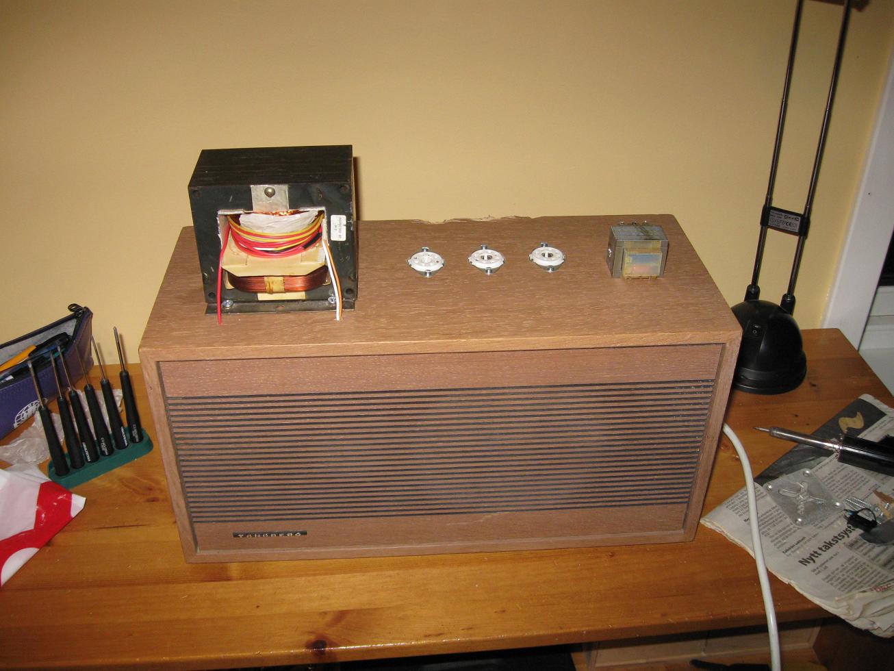
I had two old Tandberg 4 ohm speakers kicking about, and I've decided to use the one as the chassis/box. It's slightly beat-up, smells moldy, and may not function anymore, but it looks retro. I've fitted the three tube sockets on, and the modified MOT. The little mains transformer is the proposed output transformer. The ratio is about right, and the 7C5 is only good for 5W so it should be large enough. As for linearity, we'll soon see.
One hitch so far. The 7R7 has a filament resistance of 80 ohms, is it done for?
Registered Member #543
Joined: Tue Feb 20 2007, 04:26PM
Location: UK
Posts: 4992
Heater resistance:
The hot* resistance of the heater should be near to 6.3/0.3 = 21R, so the cold resistance of a healthy heater should be much less than this.
By the way, in technical English, the word filament means the filament of a directly heated valve, while the word heater is used for the heating element inside the cathode of an indirectly heated valve such as yours.
*In the data sheets, some valve parameters are considered as being in either hot condition or cold condition
Registered Member #95
Joined: Thu Feb 09 2006, 04:57PM
Location: Norway
Posts: 1308
I purchased a new tube on ebay, which arrived earlier this week. It's a 7B6 triode which I bought due to availability, and the resemblance to the 7R7 in socketing and size. A while ago I was given a bunch of old fashioned resistors and capacitors from my aunt, which belonged to her father who was, or might still be a ham. Since they're so outdated I thought they would work well to complete the vintage feel. So after some work today the amp is done, and even better it actually works! Although not perfectly yet, I'm surprised just how well. Especially since the output transformer is just an old 5V cell phone charger transformer!
The problem is the speaker sputters and pops when the volume is set beyond a certain range. At low volume, and with the sound on my ipod turned right up it sounds fine. There's some background hum, but I assume some more filtering capacitors would take care of it. If the volume is turned up any more squealing and then popping noises come from the speaker. That's really the only problem so far. I would like a good amount of gain, since I want to use it as a guitar amplifier as well, though I'm not sure if that's feasible. Do you think the impedance and/or the gain is high enough? The 40 ohm resistors on the audio output are to load it down, since I've experienced some input sources like PC audio don't work without.
Here's how I've wired it up.
Aesthetics note: the volume potentiometer e will be fixed later. The blue switch has a small lamp in it, not a blue LED so it's still retro.
Registered Member #543
Joined: Tue Feb 20 2007, 04:26PM
Location: UK
Posts: 4992
Firstly, I see that you don't have any grid bias on V1, which is specified as -2V in the data sheet. At Ia = 0.9mA, you'll need 222R (220R 5% will do fine) in the cathode line to get your 2V voltage drop on the grid. To stop negative feedback reducing the gain, you'll need to by-pass the 220R with an electrolytic of 25uf or 50uF.
And then you need to put a grid leak resistance from the grid pin to Earth. (best, the same Earth point on the chassis as the cathode line.) Best results for the grid leak resistance will be somewhere between 100K and 500K, so I'd try 270K to start with, and see how that sounds.
Hum:
Your pi ripple filter capacitor sizes look as though you have just substituted the 680R resistor for the filter choke of a valve era design. If you reckon that V2 anode plus screen are drawing 54mA and V1 anode 1mA, then you are looking at a voltage drop of nearly 40V with those values of R and C.
I suggest replacing the rectifier valve with a solid state bridge rectifier (which will load your transformer less, because you won't need the rectifier valve heater winding) and then fitting an RC filter with values, of, say 100R and 1000uF, which will give you -35dB ripple attentuation but a voltage drop of only 5 volts.
Secondly, do you have the heater wires neatly and closely twisted as you should?
Have you routed the heater line well away from the grids of V1 and V2 as you should?
Is the high impedance input to the grid of V1 well screened?
Instability: The squealing you describe is oscillation, and the popping-type noises may be either the start up of oscillation, or could be due to poor supply line regulation, or both.
Are all leads short? Are outputs routed as far away from inputs as possible?
I suggest you also decouple the heaters to Earth with 0.047uF or so at the valve socket, which is always a good precaution against unwanted signals using the heater line as a highway around the chassis.
It wouldn't harm to put some extra filtration on the HT+ line - for example, 0.01uF and 1000pF in parallel with your electrolytics which can have significant impedance at higher frequencies. Also add some capacitors to Earth whereever the HT+ supply line looks a bit long.
I also suggest you connect the unused diode anodes of V1 directly to HT+ with 4M7 or so to keep them out of mischief - don't leave them 'floating.'
Try this out, Erik, starting with the HT+ supply filter and the biasing of V1 grid so that it is operating properly, as I've suggested, and you'll quickly start to see improvements!
PS: it's very normal in testing valve circuits to have to unsolder wires so you can insert your milliammeter and check that the current is what it says it should be in the data sheet. Choose only low impedance test points, so your meter leads and their capacitance don't become an active part of the circuit. You can also deduce the cathode current, for example, (which is the anode current plus the screen grid current) by measuring the voltage drop across the cathode resistor.
There can be considerable variation of parameters between even new valves - let alone those which are half a century old - so you must expect to have to do active voltage and current measurements when setting up a circuit to make sure that the valve is working under the optimum conditions defined in the data sheet. Don't expect any very exact correlation between the data sheet and what you actually measure in real life (except for valves designated as "Special Quality" ("SQ")and such) Everyday consumer valve circuits would use 20% resistors unless real accuracy was truly needed, which gives you some idea of the wide variation in operating conditions you can expect in real life. Good luck, lad!
This site is powered by e107, which is released under the GNU GPL License. All work on this site, except where otherwise noted, is licensed under a Creative Commons Attribution-ShareAlike 2.5 License. By submitting any information to this site, you agree that anything submitted will be so licensed. Please read our Disclaimer and Policies page for information on your rights and responsibilities regarding this site.


 Grandpa's Tube Amplifier


