Steve Wards new DRSSTC driver debugging
Mads Barnkob, Thu Nov 05 2009, 08:09PMHi all
EDIT: this is without interrupter connected. Just tried with it, still excessive regulator heating.
Today I got the time to sit down and test the driver (
 ) I built after Steve's schematics (
  ) , with a few changes that might have had some impact.
Instead of the Infineon SPB18P06P MOSFET, I used ST IRF9540 MOSFET and viceversa for the N channel part, they are about even in characteristics except that the IRF9/540 MOSFET have about 3 times as high gate charge.
The driver is connected to a GDT that is connected to a half bridge of IGBTs
I left out the LM311 IC as I have no CT to connect at the moment, plugged a LED to the OCD indicator to see if it kicked in during runs, it did not.
There is no heating to be noticed on any MOSFET, IC or regulators... except that the 24V regulator supplying the MOSFET stage is about to catch fire in seconds.
I have thought about the following causes of this excessive heating on the regulator:
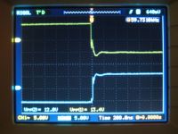
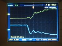
MOSFETs cross conducting and thus shorting the supply, waveforms shows there is dead time and little ringing
24V regulators capacitor is fine, 330uF, measures 348uF. No shorts over the 24V rails.
voltage on the 24V regulator is measured to 0,7V HINT! something is wrong, but somehow I doubt that the 12V supply to the MOSFET driver ic is coupling 5Vp-p through the MOSFETs to the GDT.
The feedback signal is a function generator running a square wave at 60kHz, 10Vp-p
Here are my waveforms, request more if needed
Gate waveforms

Gate waveforms zoomed on the rise/fall

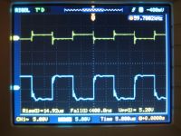
GDT secondary vs feedback input signal

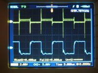
GDT primary vs feedback input signal, those peaks looks nasty

Re: Steve Wards new DRSSTC driver debugging
Z28Fistergod, Fri Nov 06 2009, 03:07AM
You should test it without any drive signal to narrow the problem down.
I'm wondering if you have enough turns on your GDT, or if you have the right core? You can try increasing the drive frequency to see if that reduces current draw.
On the last picture you have: "GDT primary vs feedback input signal," which one is which?
Completely unrelated, I noticed that you have a rigol scope. I just got their 100MHz model and it seems decent so far. How do you like yours?
Re: Steve Wards new DRSSTC driver debugging
Mads Barnkob, Fri Nov 06 2009, 05:01AM
I have tried with the GDT made for my medium DRSSTC, its 10T on a 50 mm diameter 5MHz core, i calculated a minimum of 5 turns for that core to avoid saturation, and another GDT with 15T on a smaller 25 mm diameter core that drspark sent me a while back.
First mentioned signal is on channel 1 and so forth
I have had the 50MHz Rigol DS1052E for a month or two now, I have just been too busy to sit down with the manual and get through all the stuff it can, but what I really like is the fast updating lcd display, compared to older expensive DSO, this is really fast!
The measurements menu is also a good friend, get everything in an instant. Auto button is also nice if you just have to check something fast, the scope seems sturdy and the construction / finish is just as good as what i would expect from a more expensive scope.
The PC software seems a little shady, not sure exactly where the benefit of it is now as a screencapture goes the wrong way in my mind, I want to click on my scope to save a waveform and then be able to download it to the pc, but its done from the pc which makes it a hazzle when doing some measurements.
In other words, I like it so far :)
Mads Barnkob, Fri Nov 06 2009, 05:01AM
Z28Fistergod wrote ...
You should test it without any drive signal to narrow the problem down.
I'm wondering if you have enough turns on your GDT, or if you have the right core? You can try increasing the drive frequency to see if that reduces current draw.
On the last picture you have: "GDT primary vs feedback input signal," which one is which?
Completely unrelated, I noticed that you have a rigol scope. I just got their 100MHz model and it seems decent so far. How do you like yours?
I have tried with the GDT made for my medium DRSSTC, its 10T on a 50 mm diameter 5MHz core, i calculated a minimum of 5 turns for that core to avoid saturation, and another GDT with 15T on a smaller 25 mm diameter core that drspark sent me a while back.
First mentioned signal is on channel 1 and so forth
I have had the 50MHz Rigol DS1052E for a month or two now, I have just been too busy to sit down with the manual and get through all the stuff it can, but what I really like is the fast updating lcd display, compared to older expensive DSO, this is really fast!
The measurements menu is also a good friend, get everything in an instant. Auto button is also nice if you just have to check something fast, the scope seems sturdy and the construction / finish is just as good as what i would expect from a more expensive scope.
The PC software seems a little shady, not sure exactly where the benefit of it is now as a screencapture goes the wrong way in my mind, I want to click on my scope to save a waveform and then be able to download it to the pc, but its done from the pc which makes it a hazzle when doing some measurements.
In other words, I like it so far :)
Re: Steve Wards new DRSSTC driver debugging
Z28Fistergod, Fri Nov 06 2009, 05:28AM
I see what you mean about the voltage across the GDT primary:
"voltage on the 24V regulator is measured to 0,7V"
Just to be sure, I noticed on the scope that the range does not automatically adjust for the probe attenuation factor. So is it possible that you had the scope set up for a 1X probe while the probe was actually set to 10X? Meaning that you really had 7V across the primary?
What is the current rating on the regulator? Is it possible that you are drawing too much? I see that these waveforms are without the interruptor, have you rechecked the waveforms with the interruptor?
You have one picture showing "gate waveforms" at ~12V p-p, and another showing "GDT secondary" at 1.5 p-p. I'm guessing that the "gate waveforms" are for the GDT drive circuit and not the actual IGBT halfbridge?
That's good to hear that the rigols don't explode after a few days; makes me feel better about spending so much The only thing I want to complain about is that it wont work with my USB drive. I'm not sure why yet, but hopefully it won't be too much hassle to figure out.
Z28Fistergod, Fri Nov 06 2009, 05:28AM
I see what you mean about the voltage across the GDT primary:
"voltage on the 24V regulator is measured to 0,7V"
Just to be sure, I noticed on the scope that the range does not automatically adjust for the probe attenuation factor. So is it possible that you had the scope set up for a 1X probe while the probe was actually set to 10X? Meaning that you really had 7V across the primary?
What is the current rating on the regulator? Is it possible that you are drawing too much? I see that these waveforms are without the interruptor, have you rechecked the waveforms with the interruptor?
You have one picture showing "gate waveforms" at ~12V p-p, and another showing "GDT secondary" at 1.5 p-p. I'm guessing that the "gate waveforms" are for the GDT drive circuit and not the actual IGBT halfbridge?
That's good to hear that the rigols don't explode after a few days; makes me feel better about spending so much
 The only thing I want to complain about is that it wont work with my USB drive. I'm not sure why yet, but hopefully it won't be too much hassle to figure out.
Re: Steve Wards new DRSSTC driver debugging
Mads Barnkob, Sun Nov 08 2009, 02:44PM
They are set for 10x both on the probe and scope
They are bought as 24V 1.5A ST L7824CV regulators from china
I have measured the current through it to peak at 1.3A and then it shuts down, so I am drawing too much current, I will have to find a alternative 24VDC source.
I still fail to see the course of this huge power consumption, the only difference from steves design are other MOSFETs and lower value decoupling caps in series with the GDT, the GDT is pretty much standard 10T with cat5e cable on a 5MHz core.
I have tried with interupter on and at 300 kHz, makes no difference
Gate waveforms are as you say the gates of the MOSFETs driving the GDT, GDT secondary would be the gates of the IGBTs
Mads Barnkob, Sun Nov 08 2009, 02:44PM
Z28Fistergod wrote ...
I see what you mean about the voltage across the GDT primary:
"voltage on the 24V regulator is measured to 0,7V"
Just to be sure, I noticed on the scope that the range does not automatically adjust for the probe attenuation factor. So is it possible that you had the scope set up for a 1X probe while the probe was actually set to 10X? Meaning that you really had 7V across the primary?
They are set for 10x both on the probe and scope
Z28Fistergod wrote ...
What is the current rating on the regulator? Is it possible that you are drawing too much? I see that these waveforms are without the interruptor, have you rechecked the waveforms with the interruptor?
What is the current rating on the regulator? Is it possible that you are drawing too much? I see that these waveforms are without the interruptor, have you rechecked the waveforms with the interruptor?
They are bought as 24V 1.5A ST L7824CV regulators from china
I have measured the current through it to peak at 1.3A and then it shuts down, so I am drawing too much current, I will have to find a alternative 24VDC source.
I still fail to see the course of this huge power consumption, the only difference from steves design are other MOSFETs and lower value decoupling caps in series with the GDT, the GDT is pretty much standard 10T with cat5e cable on a 5MHz core.
I have tried with interupter on and at 300 kHz, makes no difference
Z28Fistergod wrote ...
You have one picture showing "gate waveforms" at ~12V p-p, and another showing "GDT secondary" at 1.5 p-p. I'm guessing that the "gate waveforms" are for the GDT drive circuit and not the actual IGBT halfbridge?
You have one picture showing "gate waveforms" at ~12V p-p, and another showing "GDT secondary" at 1.5 p-p. I'm guessing that the "gate waveforms" are for the GDT drive circuit and not the actual IGBT halfbridge?
Gate waveforms are as you say the gates of the MOSFETs driving the GDT, GDT secondary would be the gates of the IGBTs
Re: Steve Wards new DRSSTC driver debugging
Z28Fistergod, Sun Nov 08 2009, 05:09PM
The IGBTs aren't blown are they?
That amount of current is a clear indicator that something else is wrong. I used bricks in my DRSSTC and although I didn't measue the current, the 1A regulator never gets more than luke warm. If I had to throw out a conservative guess I'd say it should be well below 0.5A.
Re: Steve Wards new DRSSTC driver debugging
Mads Barnkob, Sun Nov 08 2009, 05:23PM
The bridge is made from brand new IGBTs originial ST 30N60s
GDT driver MOSFETs are IRF(9)540 and I have measured no shorts on them.
I just checked the gate at one of the IGBTs, signal is fine at 300 kHz, but only 4.8Vp-p, could be some of the MOSFETs in the GDT driver stage is not tip top, I will look into this when I get time.
Re: Steve Wards new DRSSTC driver debugging
Mads Barnkob, Tue Nov 10 2009, 08:13PM
As I said on IRC this was properly something simple that I had totally overlooked.
I had drain and source switched around in my pcb design for the P channel MOSFETs
Mads Barnkob, Tue Nov 10 2009, 08:13PM
As I said on IRC this was properly something simple that I had totally overlooked.
I had drain and source switched around in my pcb design for the P channel MOSFETs
Re: Steve Wards new DRSSTC driver debugging
Z28Fistergod, Tue Nov 10 2009, 08:49PM
That will do it I guess. [That] Explains the 0.6~0.7 V at the supply rails.
Z28Fistergod, Tue Nov 10 2009, 08:49PM
Mads Barnkob wrote ...
...drain and source switched...
...drain and source switched...
That will do it I guess. [That] Explains the 0.6~0.7 V at the supply rails.
Re: Steve Wards new DRSSTC driver debugging
Mads Barnkob, Tue Nov 10 2009, 09:05PM
The voltage across the internal diode :)
Mads Barnkob, Tue Nov 10 2009, 09:05PM
Z28Fistergod wrote ...
That will do it I guess. Explains the 0.6~0.7 V at the supply rails.
Mads Barnkob wrote ...
...drain and source switched...
...drain and source switched...
That will do it I guess. Explains the 0.6~0.7 V at the supply rails.
The voltage across the internal diode :)
Re: Steve Wards new DRSSTC driver debugging
brtaman, Tue Nov 10 2009, 10:59PM
Glad to hear, you sorted it out.
brtaman, Tue Nov 10 2009, 10:59PM
Glad to hear, you sorted it out.

Print this page