
60KV 3.5 nF home made caps - complete protocol
Mates, Mon Sept 24 2007, 09:17PMHi guys,
Here is my complete protocol for making HV caps. It took me a while to reach this final design, so I hope you all appreciate it in your HV experiments. The caps are based on PP copolymer foils used in laser copiers and printers. Each sheet should stand 14KV and depending on how many sheets you use you can get different capacitance (two sheets 9nF - six sheets 3.5 nF). Picture is more than 100 words so have a look...Used alu-foil is the fat one (for grilling). Have fun... Mates
Total number of sheets 15 per cap (2 for covering each alu-sheet, 5 between the covered alu- sheets, 5 on top of the second covered alu-sheet and one more for final rolling)
Size of alu sheet 22x15.5 cm
BTW: I hope you all already have the hot-glue pistol!
According to the longevity:
The PP copolymer should be very resistant against ozone. I'm using these caps in my MARX generator and I have no fails after more than 100 shots. Also in my small TC these caps works without breakdown for quite a long time. But of course this is not professional product so I can not promise 1000h of continual work...
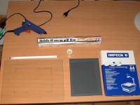
The required tools and supplies.
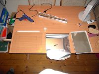
Cut the foil to size using a sharp knife
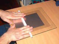
Use a smooth rolling pin (made of small fluorescent tube) on a smooth surface to get rid of as much air as possible. Air bubbles will cause corona and ozone to form above a certain voltage/frequency
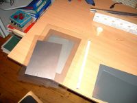
Interleave the plastic sheets (5pc) between and above the already made doublets with aluminium foils between.
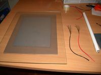
Use the rolling pin again and prepare the cables by removing 5-6cm of the isolation
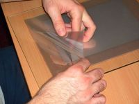
Find the upper aluminium foil and place the firts cable on it. Let only the unisolated part of the cable in the contact with the aluminium foil.
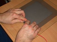
Tricky part one: Roll the sheets slowly...
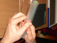
Find the most upper sheet (the lowest one before rolling)
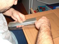
Tricky part two: Unroll the most upper sheet until the second aluminium foil is exposed. Place the cable and roll it back. Hold the cap properly during this process otherwise it can unroll very quickly in your hand and you have to start again!
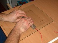
Use one or two more sheets to roll over to protect unrolling and it also makes the upper aluminium foil more than one sheet isolated.
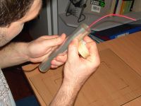
Use the glue tape to protect unrolling.
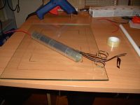
Use the scissors and follow the upper cable with the tip and cut a track for it.
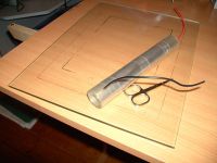
Put the cable through the track you have cut with the scissors. This is important for gluing the sides of the capacitor.
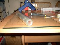
Cut the same track for the inner cable...
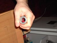
Place the inner cable inside the capacitor. You remove it back after the ends are glued.
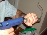
Use the glue pistol to put some more easy-to-melt plastic at the ends and fix and isolate the cables with the glue properly!
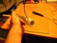
Do the same on the other end.
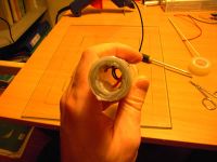
Final appearance before gluing
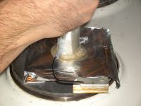
Tricky part three: Push the end of the capacitor against preheated metal plate (use an electric cooker) to melt the PP foils and the hot-glue into a compact structure. This is very improtant part which needs a lot of focus. It will protect the cap before the side spark-overs. (Side spark-overs are the biigest risk for the final capacitor).
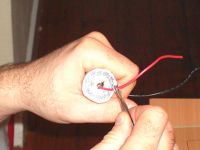
Remember to remove the inner cable. In case the whole is blinded after the previous step make a whole with a pencil while the plastic is still hot and soft.
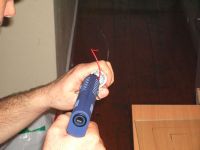
Use more hot-glue to fix and isolate the cables. It is good idea to put additional PVC or silicon tubing around the cables and glue it to the main body of the capacitor.
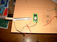
Check the capacitance
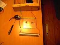
Test setting for the capacitor. Use the spark gap distance to set the final volatage to approx. 50-60KV DC (5-6cm distance)
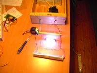
Put some earplugs and sunglasses and let the capacitor run for while. Remember discharge properly the capacitor after the test (and any other) run. It can store the charge for a long time and touching both ends of 3.5nF cap loaded to 50KV is shocking experience!
Re: 60KV 3.5 nF home made caps - complete protocol
Sulaiman, Tue Sept 25 2007, 04:32AM
Nice work but I have to ask;
how long have you run your capacitors with hv applied?
In the 80's I made various home-rolled capacitors and to cut a long story short -
if there was any air in the foil/dielectric they eventually failed
due to ozone created by internal corona 'eating' the dielectric.
Unless you can roll and seal them in a vacuum
or fill the capacitor with oil
I think yours will also fail.
Apply hv to your capacitor(s) and observe them in the dark (needs caution!)
ANY sign of bluish light means they WILL fail.
If you don't see any corona then WELL DONE !!
Re: 60KV 3.5 nF home made caps - complete protocol
Simon, Tue Sept 25 2007, 11:20PM
Do you have a wiki account? This is just the kind of thing we'd love to have there.
Simon, Tue Sept 25 2007, 11:20PM
Do you have a wiki account? This is just the kind of thing we'd love to have there.
Re: 60KV 3.5 nF home made caps - complete protocol
Tesladownunder, Mon Dec 24 2007, 01:04AM
The prime example of a failure prone cap is in a TEA laser where you can have only a thin layer of dielectric and need a moderate voltage across it. Failure is common as 10kV plus is aplied continuously. However if you use a Marx to charge it in a few microseconds, a higher voltage can be applied and longevity is improved, presumably as the voltage is only applied momentarily. Less time for corona to do damage.
Of course at 60kV, everything will light up with corona.
TDU
Tesladownunder, Mon Dec 24 2007, 01:04AM
Sulaiman wrote ...
Unless you can roll and seal them in a vacuum
or fill the capacitor with oil
I think yours will also fail.
Apply hv to your capacitor(s) and observe them in the dark (needs caution!)
ANY sign of bluish light means they WILL fail.
Not sure if I agree 100%. Caps you made in the 80's may have failed in TC use. This is 100% reversal stuff, not just intermittent DC charging.Unless you can roll and seal them in a vacuum
or fill the capacitor with oil
I think yours will also fail.
Apply hv to your capacitor(s) and observe them in the dark (needs caution!)
ANY sign of bluish light means they WILL fail.
The prime example of a failure prone cap is in a TEA laser where you can have only a thin layer of dielectric and need a moderate voltage across it. Failure is common as 10kV plus is aplied continuously. However if you use a Marx to charge it in a few microseconds, a higher voltage can be applied and longevity is improved, presumably as the voltage is only applied momentarily. Less time for corona to do damage.
Of course at 60kV, everything will light up with corona.
TDU
Re: 60KV 3.5 nF home made caps - complete protocol
Logan Kennedy, Mon Dec 24 2007, 05:10AM
I've made a few of these before, but I could never remove all the air from the conductor/dielectric layers. I never ran them for too long, so they still haven't failed. However I'm sure they would fail quite quickly if ran under extended duty.
I will have to use your method and see if I can produce a halfway decent DIY HV capacitor.
The best thing: they're cheap and fairly easy to make, and losing one or two during operation isn't too much of a loss.
Re: 60KV 3.5 nF home made caps - complete protocol
cbfull, Sat Dec 29 2007, 02:05AM
When I made my first HV cap I used glass sheets and Al foil. I left it dry and the whole thing would light up blue with corona. I decided to fill it with oil and not only did the corona stop, the performance of it improved drastically.
Not a suggestion, just an individual observationa
Re: 60KV 3.5 nF home made caps - complete protocol
Dr. Dark Current, Sat Dec 29 2007, 09:52AM
Just a stupid suggestion, maybe you can "paint" the caps with oil before rolling them?
Dr. Dark Current, Sat Dec 29 2007, 09:52AM
Just a stupid suggestion, maybe you can "paint" the caps with oil before rolling them?
Re: 60KV 3.5 nF home made caps - complete protocol
cbfull, Sat Dec 29 2007, 08:45PM
That's not a stupid idea by any means! Ideally, just about any device handling high voltages would be pre-wetted or "painted" as you say with whatever insulating material is desired (oil, epoxy, etc.). Unfortunately in this hobby the equipment is not already built with our interests in mind.
What is typically done to extend the life of a HV device is to submerge the device (transformer, capacitor, rectifier) in the liquid insulating media and then pull as strong a vacuum as possible to remove as much air as possible from every nook and crannie. Pre-wetting during assembly could cut vacuum treatment times to a mere fraction.
Not sure if you are already aware of this but as an engineer I had to point out how practical and sensible that idea is.
cbfull, Sat Dec 29 2007, 08:45PM
jmartis wrote ...
Just a stupid suggestion, maybe you can "paint" the caps with oil before rolling them?
Just a stupid suggestion, maybe you can "paint" the caps with oil before rolling them?
That's not a stupid idea by any means! Ideally, just about any device handling high voltages would be pre-wetted or "painted" as you say with whatever insulating material is desired (oil, epoxy, etc.). Unfortunately in this hobby the equipment is not already built with our interests in mind.
What is typically done to extend the life of a HV device is to submerge the device (transformer, capacitor, rectifier) in the liquid insulating media and then pull as strong a vacuum as possible to remove as much air as possible from every nook and crannie. Pre-wetting during assembly could cut vacuum treatment times to a mere fraction.
Not sure if you are already aware of this but as an engineer I had to point out how practical and sensible that idea is.
Re: 60KV 3.5 nF home made caps - complete protocol
Mates, Sun Dec 30 2007, 05:00PM
According to the oil suggestion...
My first rolled capacitors were combined with a silicon oil. Honestly, I had to leave the concept when I started to play with voltages over 40KV. Problem was, that the oil made impossible to glue the sheets on the sides and the caps started to spark on the sides... Moreover, once the spark started it made carbonized path and decreased the breaktrough voltage very rapidly and the cap was more or less destroyed...
I think, the corona problem is not so big like most of you suggest. The latest version of my caps are very robust and I have not destroyed a single one even by playing with voltages close to 60KV reaching hundreds of hard (no load) discharges. (Of course I mean DC...)
Cheers Mates
Re: 60KV 3.5 nF home made caps - complete protocol
MOT_man, Tue Jan 01 2008, 09:27AM
I just built a capacitor using your technique and poly sheeting from overhead enlargers. I tried 7 kV (AC) pulsed a couple of times through the capacitor. I saw some weak corona - but it wasn't bad. I also tried to vacuum seal the capacitor in a 2" PVC housing with end caps - poured in mineral oil and then vacuumed the whole lot. Seems to work fine... I'm sure 10 kV might be a bit much.... but I'll try it an see.
Just slide the hand rolled capacitor down the PVC tube and presto - I think my capacitors comes out to 8 nF due the number of layers I used. - It's a great idea! Thanks for the inspiration!
--- just tried 10kV ... no problems. 10 second burst...
--- just tried 12 kV NST.... no problems.... 10 second burst
Re: 60KV 3.5 nF home made caps - complete protocol
Arcstarter, Mon May 05 2008, 07:23PM
This s quite an old topic, but i would like to bring it up again.
Has anyone used this in tesla coil duty? I am going to head to office depot and pick some up, because everything i have tried failed miserably, either by arc-overs or not enough capacitance even though it is very large. The only caps i could afford are pieces of (Ill let you fill in the blank).
I am going to use 2 sheet and make a few of those because i need a 20nf capacitor and a 40nf capacitor. The capacitors will be used at 6kv for the 20nf and 16kv for the 40nf. Do you think 2 sheets will be sufficient for short runs at 16kv max?
Re: 60KV 3.5 nF home made caps - complete protocol
Mates, Mon May 05 2008, 07:43PM
I used these caps for my MOT + voltage quadrupler driven SG coil and I had no failure (and it was single sheet design - it means three sheets per cap in total). But it was only short time tested - I had to give up with this coil because it was too noisy for a "block of flats" use.
Since you are going to use two sheets design (it means 4sheets per cap in total) you don't need to glue the sides of the caps and for 16KV two sheets should be far enough (each sheet can stand 14KV). And there is no point of using oil unless you own vacuum pump. It’s messy and makes the cap even more vulnerable (ozon + oil = nasty acids eating the PP-CP). Good luck and let us know how it works…
BTW: in Hv-Wiki in how to section is a bit better version of the protocol...
One more thing: I find out that its better to use more caps in series rather then adding more sheets in case you want higher voltage raitng. You will never need to perform the side-gluing part of the protocol. So ideal design is two sheetsbased caps (4sheets in total = 25KV rated) used it in a MMC setup like I used in this project , however it has higher space demands...
Mates, Mon May 05 2008, 07:43PM
I used these caps for my MOT + voltage quadrupler driven SG coil and I had no failure (and it was single sheet design - it means three sheets per cap in total). But it was only short time tested - I had to give up with this coil because it was too noisy for a "block of flats" use.

Since you are going to use two sheets design (it means 4sheets per cap in total) you don't need to glue the sides of the caps and for 16KV two sheets should be far enough (each sheet can stand 14KV). And there is no point of using oil unless you own vacuum pump. It’s messy and makes the cap even more vulnerable (ozon + oil = nasty acids eating the PP-CP). Good luck and let us know how it works…
BTW: in Hv-Wiki in how to section is a bit better version of the protocol...
One more thing: I find out that its better to use more caps in series rather then adding more sheets in case you want higher voltage raitng. You will never need to perform the side-gluing part of the protocol. So ideal design is two sheetsbased caps (4sheets in total = 25KV rated) used it in a MMC setup like I used in this project
 , however it has higher space demands...
Re: 60KV 3.5 nF home made caps - complete protocol
dingo27, Mon May 05 2008, 09:35PM
and what about design with no rolling, just more plates??? i think it will be easier to build, less space needed, and you can add it in plexiglass so the plexi will do a pressure on it...
dingo27, Mon May 05 2008, 09:35PM
and what about design with no rolling, just more plates??? i think it will be easier to build, less space needed, and you can add it in plexiglass so the plexi will do a pressure on it...
Re: 60KV 3.5 nF home made caps - complete protocol
Mates, Mon May 05 2008, 10:07PM
1) Rolled cap has bigger capacitance
2) Unrolled cap will be flat but otherwise the full A4 size !
3) Plexiglass is another extra material, which means extra costs and extra processing work
In general the flat design is doable but seems unpractical to me... but feel free to try your own design and let us know
Mates, Mon May 05 2008, 10:07PM
dingo27 wrote ...
and what about design with no rolling, just more plates??? i think it will be easier to build, less space needed, and you can add it in plexiglass so the plexi will do a pressure on it...
and what about design with no rolling, just more plates??? i think it will be easier to build, less space needed, and you can add it in plexiglass so the plexi will do a pressure on it...
1) Rolled cap has bigger capacitance
2) Unrolled cap will be flat but otherwise the full A4 size !
3) Plexiglass is another extra material, which means extra costs and extra processing work
In general the flat design is doable but seems unpractical to me... but feel free to try your own design and let us know

Re: 60KV 3.5 nF home made caps - complete protocol
Tesladownunder, Tue May 06 2008, 07:08AM
I have plans for a Tesla suitable rolled cap which might just be good enough to be used without oil and be easy to make. Hopefully a significant improvement on the old rolled caps which were prone to failure even with oil.
There have been a few insights into rolled cap making now that I have experience and a better understanding of the spiral line impulse generator.
I really need to make it up and do the testing first though and I have a few other things on the go at present. I should also do a detailed contruction sequence like the comprehensive one Mates has done.
TDU
Re: 60KV 3.5 nF home made caps - complete protocol
Arcstarter, Fri May 09 2008, 04:38AM
 .
.
Arcstarter, Fri May 09 2008, 04:38AM
Tesladownunder wrote ...
I have plans for a Tesla suitable rolled cap which might just be good enough to be used without oil and be easy to make. Hopefully a significant improvement on the old rolled caps which were prone to failure even with oil.
There have been a few insights into rolled cap making now that I have experience and a better understanding of the spiral line impulse generator.
I really need to make it up and do the testing first though and I have a few other things on the go at present. I should also do a detailed contruction sequence like the comprehensive one Mates has done.
TDU
Well whenever you get those caps made, give us the instructions, I am sure alot of us would use it and really appreciate it. Now all i have to do is make a transformer (not) and every part on my tesla coil is home made I have plans for a Tesla suitable rolled cap which might just be good enough to be used without oil and be easy to make. Hopefully a significant improvement on the old rolled caps which were prone to failure even with oil.
There have been a few insights into rolled cap making now that I have experience and a better understanding of the spiral line impulse generator.
I really need to make it up and do the testing first though and I have a few other things on the go at present. I should also do a detailed contruction sequence like the comprehensive one Mates has done.
TDU
 .
.Re: 60KV 3.5 nF home made caps - complete protocol
lpfthings, Fri May 09 2008, 09:29AM
wow, so simple yet effective. A tesla coil is beginning to become more of a reality. Just gotta find some wire......
lpfthings, Fri May 09 2008, 09:29AM
wow, so simple yet effective. A tesla coil is beginning to become more of a reality. Just gotta find some wire......
Re: 60KV 3.5 nF home made caps - complete protocol
Arcstarter, Mon May 12 2008, 06:41PM
Ok, so my birthday was yesterday and i got some transparencies. They work good and have quite high capacitance. But no matter how many i use, i still get much poorer performance that the cje caps i used. Maybe i just haven't found the ideal capacitance? Or is it because of inductance and other stuff i know nothing about?

Re: 60KV 3.5 nF home made caps - complete protocol
Mates, Mon May 12 2008, 07:25PM
I do not understand your point. The capacitance is defined by the size of the alu foil (how bigger so bigger) and by the distance between these foils (how smaller so bigger). Special factor is the rolling...
So if you use only one sheet of transparency isolating the two alu foils (three transparencies in total) than you should see like 12-13nf and the cap should stand 14KV... I do not know what is it cje but i think that is quite a powerful and cheap cap.
BTW: I tested these caps with my flyback based SGTC recently and they work fine... No problems after really long run - the caps get only litle bit warm (corrona losses) but the dielectricum looks uneaten...
Mates, Mon May 12 2008, 07:25PM
Arcstarter wrote ...
Ok, so my birthday was yesterday and i got some transparencies. They work good and have quite high capacitance. But no matter how many i use, i still get much poorer performance that the cje caps i used. Maybe i just haven't found the ideal capacitance? Or is it because of inductance and other stuff i know nothing about?
Ok, so my birthday was yesterday and i got some transparencies. They work good and have quite high capacitance. But no matter how many i use, i still get much poorer performance that the cje caps i used. Maybe i just haven't found the ideal capacitance? Or is it because of inductance and other stuff i know nothing about?

I do not understand your point. The capacitance is defined by the size of the alu foil (how bigger so bigger) and by the distance between these foils (how smaller so bigger). Special factor is the rolling...
So if you use only one sheet of transparency isolating the two alu foils (three transparencies in total) than you should see like 12-13nf and the cap should stand 14KV... I do not know what is it cje but i think that is quite a powerful and cheap cap.
BTW: I tested these caps with my flyback based SGTC recently and they work fine... No problems after really long run - the caps get only litle bit warm (corrona losses) but the dielectricum looks uneaten...
Re: 60KV 3.5 nF home made caps - complete protocol
Arcstarter, Mon May 12 2008, 07:35PM
Oops. I forgot what i was saying while i was typing. Don't ask. I meant on my tesla coil. I used them on my tesla coil and i got less performance than with a capacitor bought on ebay. And now i have one of them arcing over. But i can see the corona which looks like the sparks off the tesla coil but alot more sparks but alot shorter.
Re: 60KV 3.5 nF home made caps - complete protocol
dingo27, Mon May 12 2008, 09:44PM
yeah, i tried this with cover from my physics school notebook (at least notebooks have some use :) ) but i did not see that i need more plates... i used only 3 layers (foil, aluminium, foil, al, foil )... first run in TC BANG... one was good second not, but as i was not sure i disassembled both...
next day i assembled one and it is ready to test in less powerful TC i am building tomorrow...
Re: 60KV 3.5 nF home made caps - complete protocol
Mates, Wed May 14 2008, 09:43PM
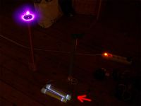
OK guys, I decided to test these caps in the TC use properlly. I built this simple fly-back driven SGTC and let it run for long minutes... (min 30min total time). You can see on the picture the huge corona losses inside the caps, but the caps are still alive. The dielectric layer shows some kind of track-like pattern in the corona most exposed parts, but nothing critical. I will let them run as long as possible and then I will make detailed inspection of the PP-CP dielectricum...
cheers...

Re: 60KV 3.5 nF home made caps - complete protocol
flannelhead, Thu May 15 2008, 12:39PM
Pretty long exposure... Was it the whole 30min?
flannelhead, Thu May 15 2008, 12:39PM
Pretty long exposure... Was it the whole 30min?

Re: 60KV 3.5 nF home made caps - complete protocol
lpfthings, Thu May 15 2008, 09:54PM
LOL the whole caps are glowing white!!
So if i got a peice of plexiglass, stuf a peice of foil on one side, then another peice on the other side, i'd have a HV cap?!?!?
Do you only need one layer is what i'm asking lol
lpfthings, Thu May 15 2008, 09:54PM
LOL the whole caps are glowing white!!
So if i got a peice of plexiglass, stuf a peice of foil on one side, then another peice on the other side, i'd have a HV cap?!?!?
Do you only need one layer is what i'm asking lol
Re: 60KV 3.5 nF home made caps - complete protocol
Bjørn, Thu May 15 2008, 10:23PM
Yes and read this:
Bjørn, Thu May 15 2008, 10:23PM
Yes and read this:

Re: 60KV 3.5 nF home made caps - complete protocol
aonomus, Thu May 22 2008, 08:30PM
This might seem counterintuitive, but would it not be possible to roll the caps, seal them on the hotplate, and then use a hypodermic needle to inject mineral oil in one cavity while pulling vacuum on the other end? Sure you put two holes into your dielectric, but since the cap is a big jelly roll injecting oil from the outer layer at one end, and pulling vacuum from the inner layer might work to pull a fair amount of oil in.
And something tells me those caps that were glowing white might have the foil melted to the plastic.
Re: 60KV 3.5 nF home made caps - complete protocol
Sulaiman, Thu May 22 2008, 09:00PM
All of this is well covered in the pupman archives - if they're still available.
..just checked - they're still available.
Sulaiman, Thu May 22 2008, 09:00PM
All of this is well covered in the pupman archives - if they're still available.
..just checked - they're still available.
Re: 60KV 3.5 nF home made caps - complete protocol
Dr. SSTC, Sat Jun 21 2008, 02:17AM
lol how about making the whole capacitor in a oil bath
na just joking
Dr. SSTC, Sat Jun 21 2008, 02:17AM
lol how about making the whole capacitor in a oil bath
na just joking
Re: 60KV 3.5 nF home made caps - complete protocol
quicksilver, Sat Jun 21 2008, 02:50PM
There are several "paper covers" available. How does one tell the mylar material from others? How do you know if you have the correct material???
quicksilver, Sat Jun 21 2008, 02:50PM
There are several "paper covers" available. How does one tell the mylar material from others? How do you know if you have the correct material???
Re: 60KV 3.5 nF home made caps - complete protocol
Firefox, Sat Jun 21 2008, 07:51PM
I just made it simple and asked my science teacher for some overhead slides before I graduated. I've tested them to around 7-10kV and they work great.
Firefox, Sat Jun 21 2008, 07:51PM
I just made it simple and asked my science teacher for some overhead slides before I graduated. I've tested them to around 7-10kV and they work great.
Re: 60KV 3.5 nF home made caps - complete protocol
Hon1nbo, Sat Jun 21 2008, 08:18PM
does anyone know the dielectric constant for NaCl (uniform solid crystal)... assuming no moisture? I may not use it, but I have been thinking of doing some experimentation with electricity induced fractures in crystals...
and oil is always a good idea, anything that I want to last long that I do not plan to adjust (above 5kV) I put in oil... same for long runs of wire that are too long for HV wire, the wire goes in a tube filled with oil with something to hold it in place...
also, this might be a good idea for the wiki: real world uses and ratings for dielectrics
Re: 60KV 3.5 nF home made caps - complete protocol
Dr. Dark Current, Sat Jun 21 2008, 08:22PM
Dr. Dark Current, Sat Jun 21 2008, 08:22PM
DaJJHman wrote ...
and oil is always a good idea, anything that I want to last long that I do not plan to adjust (above 5kV) I put in oil... same for long runs of wire that are too long for HV wire, the wire goes in a tube filled with oil with something to hold it in place...
What oil do you use?and oil is always a good idea, anything that I want to last long that I do not plan to adjust (above 5kV) I put in oil... same for long runs of wire that are too long for HV wire, the wire goes in a tube filled with oil with something to hold it in place...
Re: 60KV 3.5 nF home made caps - complete protocol
Aziz Efendi, Sat Jul 23 2011, 12:36PM
Hi mates ....
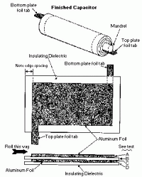
Whether in making the capacitor does not require a mandrel in the middle so that there is no possibility of air entering into the capacitor ....?
as shown below :
Aziz Efendi, Sat Jul 23 2011, 12:36PM
Hi mates ....
Whether in making the capacitor does not require a mandrel in the middle so that there is no possibility of air entering into the capacitor ....?
as shown below :

Re: 60KV 3.5 nF home made caps - complete protocol
Tony Matt, Sun Jul 24 2011, 04:34PM
Hi !
I have been involved in this matter for years...
a- it is really hard to eliminate any air portion in the cap assembly. Even with vacuun and oil impregnation the hv cap may have some air portion that will glow and produce ozone... damaging the solid dielectric...
The solution for that appears not be new. What about:
1- Design a capacitor that have a dielectric media compound of air dielectric and solid dielectrc. ?
2- The relation between the air dielectric thickness to the solid dielectric thickness is such that the voltage gradient is lower than the corona voltage level.
Thanks
Tony
Re: 60KV 3.5 nF home made caps - complete protocol
Patrick, Sun Jul 24 2011, 11:06PM
Does the field intensity play a role in oil break down? i have field sims showing 12MegaVolts/m on 0.5mm distances with 14kV applied, to plates 0.004 radius thick, 1.4mm apart in oil, but an average of 310V per mil?(or 12KV per mm) Any advice?
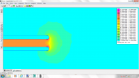
Density plot, Rounded edges, without equipotential lines.
Im getting a calulated intensity of 14kV/0.055" = 254V/mil
But the program shows 45,000V/mil !? how is this possible?
(The orange in the middle gap is 1.711e9 V per m.)
UPDATE: my thread here explains what ive found->
Patrick, Sun Jul 24 2011, 11:06PM
Does the field intensity play a role in oil break down? i have field sims showing 12MegaVolts/m on 0.5mm distances with 14kV applied, to plates 0.004 radius thick, 1.4mm apart in oil, but an average of 310V per mil?(or 12KV per mm) Any advice?

Density plot, Rounded edges, without equipotential lines.
Im getting a calulated intensity of 14kV/0.055" = 254V/mil
But the program shows 45,000V/mil !? how is this possible?
(The orange in the middle gap is 1.711e9 V per m.)
UPDATE: my thread here explains what ive found->

Patrick wrote ...
UPDATE:[/size]
pics

Voltage plot. (right side has rounded edges) Upper magenta is 14kV, lower cyan is 0 volts, midpoint of gap is yellow 7 kV as would be expected.
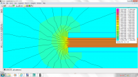
Field density plot, V/m. Left side, right angled edges W/ equipotential lines.

Density plot, Rounded edges, without equipotential lines.
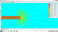
Density plot, Rounded edges, with equipotential lines.
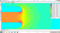
Round edges, Density plot, zoomed in.
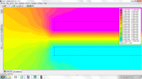
Square left end, voltage plot.
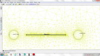
Horizontal top plate should be 14kV, lower plate 0V, two circles at right and left should be 7kV, DXF is in inches. I cant figure out how to work this dam software!
( DXF file for FEMM4.2)(newest)
UPDATE:[/size]
pics

Voltage plot. (right side has rounded edges) Upper magenta is 14kV, lower cyan is 0 volts, midpoint of gap is yellow 7 kV as would be expected.

Field density plot, V/m. Left side, right angled edges W/ equipotential lines.

Density plot, Rounded edges, without equipotential lines.

Density plot, Rounded edges, with equipotential lines.

Round edges, Density plot, zoomed in.

Square left end, voltage plot.

Horizontal top plate should be 14kV, lower plate 0V, two circles at right and left should be 7kV, DXF is in inches. I cant figure out how to work this dam software!
( DXF file for FEMM4.2)(newest)
Print this page