
RGB LASER
..., Sun Mar 25 2007, 10:57PMEDIT- scroll down to find revision 3 built and working!
For my 1000th post...
I was looking at my available laser parts, and decided to to make a red+green laser, and hopefully add in a 405nm blue diode from a blu-ray/hd-dvd player sometime to make it a full color red+green+blue laser.
In any case, the first step was to package the red diode, since it was just a bare diode.
A little more looking turned up a little heatsink, and some thermally conductive epoxy, which led to this
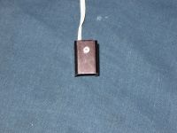
Then, I dug up a collimator that was given to me in a different laser order and found that it needed to be held about .2" away from the heatsink, and held there to within ~+/-.002". A little more head scratching turned up some nylon washers, so I glued one to each side of the assembly. Then I took some 300grit sand paper, and slowly ground down one of the washers until the beam was colminated. I forgot to take a pic of the finished laser, but you can see it pretty clearly in the latter pics.
The second step was to get some green, and after a few quick decisions it was determined that I needed about 3mw of 532nm. The huge difference in power (80mw red vs 3mw green) is because the 650nm diode I used is actually almost IR rather than red. This is good because it gives a very deep/rich red, but bad because you need a ton of power to get a decent perceived brightness. Then, I though about using a Nd:YVO4/KTP crystal and a 1w 808nm laser diode (a piece of one of my 25w laser diode bars) to DIY the green laser, but I decided that since I needed soo little power I would just use the guts of a green pointer that I had handy, which really simplified things. To had diy'ed it I would have had to do the alignment for the diode, the crystal, and a 5x or preferably 10x beam expander to get a mildly collimated beam, and it would have ended up costing way more than the $30 for a complete module with an integrated sense photodiode and even a driver board (but I scraped that since I need analog modulation for later)
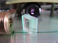
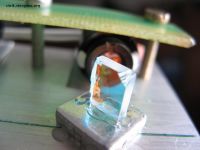
Then I needed to dicrotic mirror that would reflect as much of the red beam, and as little of the green beam as possible, and I found a turning mirror out of a dvd-rom to do the job quite well. (it passes about 5% of the red, and 80% of the green at 45degrees IIRC).
The final step (well, until I cough up the $$ for a blue diode) was to mount the optics in a stable package. Now, this would be impossibly hard for many people, as to get the beams to look collinear at and distance you need to keep the beams within +/-.2mRAD (.01degrees), and aligned to within +/-.01" in x/y. Luckily I happened to have a ton of nice optical stages around, so I just made up a little 5 axis aligner, and did the alignment.
To make sure the beams were perfectly collinear I put a little bounce mirror at the far side of the lab (aka, bedroom) and send the beam back toads me. Then, I used a squirtbottle of water set for a fine mist to create a dense fog to see the beams. From there, I could easily get them aligned to within .01" at 20'.
But then I ran into trouble, keeping the stuff in place. The 1.0 revision was done with a ton of CA glue, but the combiner mirror was up on a big block of plastic and likewise was really loose (gently pushing on it would send the beams out of alignment like .5")
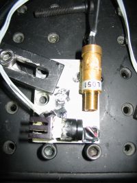
So I decided that if I was going to pull it all apart I would make room for the blue laser, and neaten up the beams a little, so I cut a piece of aluminum heatsink and used that for a base. To attach the optics I used some UV cure epoxy, and all was going well until I tried the alignment. First, I tried with the UV epoxy, I got everything aligned, hit it with 10 seconds of UV and then noticed that the beam had walked a solid .5" from where it started, because as the epoxy cured it expanded slightly. So I decided to try some normal 5 minute epoxy. I mixed up a batch, dribbled some on the 2 parts I was aligning (since I was using a 90degree turning mirror for the green I had to align both the mirror and the laser at the same time) and dialed in the alignment. But, then as I waited for the epoxy to cure I noticed the beam slowly walking away (over an hour it would drift about .1"). So I tried touching the parts I had already mounted, and of course even the slightest pressure sent the beams out of alignment, and they were slowly drifting around.
So now I am on the hunt for some decent UV cure epoxy that doesn't expand/shrink much, and most importantly, cures 100% solid...
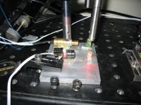
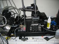
In any case, it did stay aligned long enough to try to take a few pics of the beam, although laser beams ae hard beasts to photograph.
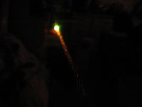
edit:
Blue laser diode acquired. Well, technically it is way closer to UV at 405nm, which is roughly as bright as far as lumens/watt as 730nm near IR light, at about 1/2,000 as visible as 555nm in bright light. However, when your eyes are dark adjusted they are more sensitive to UV, and it becomes about as bright as 620nm light, which is quite visible at about 1/150 as bright as 500nm. Also, keep in mind that eyes have a nonlinear response curve to brightness, so in reality it takes about 5x as much 405nm to be as bright as a 532nm yag laser.
However, the fact that it is UV works out great, as so long as you use a fluorescing target (white paper, or dust) it fluoresces at that electric blue that bleached paper does under a blacklight

In any case, I hooked him up with a culminating lens, and now I have a beautiful beam running around. Admittedly, there is a TON of scatter (I am not sure exactly why, I think it could be related to using a very short focal length lens for collimation (like .2"), or the fact that I used a plastic lense coated for who knows what with a UV laser diode, but in any case there is more power going into the scatter than the beam

Bit of trivia, 405nm laser diodes (at least the one I have) are actually glass clear! Unlike the 'normal' GaAs laser diodes which are pitch black, you can see right through this guy. I am not sure if the laser is actually grown in the clear substrate, more likely it was grown on top, however it was quite a surprise when I took a look at him under the microscope and was met with a water clear laser diode. I just wish I could see a full wafer of those!
peter
Re: RGB LASER
..., Sat Apr 14 2007, 09:27AM
wehe! now I can say that I have built a white light laser
In any case, turns out the problem with the 405nm diode was that there was a tiny spot of glue right centered on the window of the package which was screwing with my beam, so after removing that I had a decent culminated UV laser.
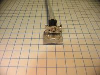
That is the laser I carefully removed (see the pr0n ), I just glued a Fl 0.2" lens on iit, much like I did for the red one.
Then it was a 'simple' matter of gluing everything down to a plate of aluminum. I will spare you the details, and leave it at that I still need to rip out the blue diode and redo the alignment for their red before I can call this finished...
That got me here:
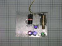
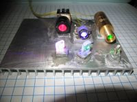
the optics assembly
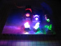
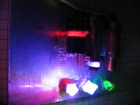
without a flash


all lasers running (powers adjusted to look white, but the camera didn't pick the green as it should, and with just the blue/green lasers
just blue and red/blue
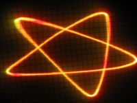
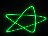
red/green as just green
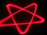
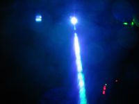
just red, and the blue/green lasers powered up with a little water vapor
..., Sat Apr 14 2007, 09:27AM
wehe! now I can say that I have built a white light laser

In any case, turns out the problem with the 405nm diode was that there was a tiny spot of glue right centered on the window of the package which was screwing with my beam, so after removing that I had a decent culminated UV laser.

That is the laser I carefully removed (see the pr0n
 ), I just glued a Fl 0.2" lens on iit, much like I did for the red one.
Then it was a 'simple' matter of gluing everything down to a plate of aluminum. I will spare you the details, and leave it at that I still need to rip out the blue diode and redo the alignment for their red before I can call this finished...
That got me here:


the optics assembly


without a flash


all lasers running (powers adjusted to look white, but the camera didn't pick the green as it should, and with just the blue/green lasers


just blue and red/blue


red/green as just green


just red, and the blue/green lasers powered up with a little water vapor
Re: RGB LASER
ragnar, Sat Apr 14 2007, 10:34AM
UNbelievable, Peter! This is outstanding.
They look quite well aligned -- collimation is quite good?
ragnar, Sat Apr 14 2007, 10:34AM
UNbelievable, Peter! This is outstanding.
They look quite well aligned -- collimation is quite good?
Re: RGB LASER
Electroholic, Sat Apr 14 2007, 10:56AM
holy shit thats quite a setup you got there.
so what kind of glue did you use at last?
Electroholic, Sat Apr 14 2007, 10:56AM
holy shit thats quite a setup you got there.
so what kind of glue did you use at last?
Re: RGB LASER
..., Sat Apr 14 2007, 05:21PM
I ended up using a bottle of 'gap filling' (really thick) CA (superglue) and some accelerator (some really nasty stuff that you spray on it that makes it cure at like 100x). That stuff is the most brittle that I could find, but it still is too flexible. I am aiming to keep the beams collinear, so I have to keep them aligned better than the divergence of the beams (about .8mrad or so), which I don't think is possible the way I have the mirrors mounted.... As it is, gently pushing on them can walk the beam about 5mrad
My plan now is to pile a ton of glue on the lasers (you see, the lasers are round, and I don't have the means to machine a matching piece of aluminum to mount them to, so I am using a big glob of glue, which sorta works but I can still walk the beam about 3mrad with mild pressure on them) and then add some aluminum plates on the sides of the mirror to help stabilize them.
I am also worried about my uv laser, as it has way more divergence than the other ones, so at long distances there is a yellow spot surrounded by a purple glow more than there is a white spot. But even more worrisome is that the beam is most definitely not a Gaussian profile, more of an eye shape with a big vertical plume. I am thinking of ditching my homebrew collimator and putting it in a small commercial one that had a red diode in it, and seeing if that helps.
Oh well, it works and the proof of concept is there. Now I just need to get it boxed up and with a decent beam
..., Sat Apr 14 2007, 05:21PM
I ended up using a bottle of 'gap filling' (really thick) CA (superglue) and some accelerator (some really nasty stuff that you spray on it that makes it cure at like 100x). That stuff is the most brittle that I could find, but it still is too flexible.
 I am aiming to keep the beams collinear, so I have to keep them aligned better than the divergence of the beams (about .8mrad or so), which I don't think is possible the way I have the mirrors mounted.... As it is, gently pushing on them can walk the beam about 5mrad
My plan now is to pile a ton of glue on the lasers (you see, the lasers are round, and I don't have the means to machine a matching piece of aluminum to mount them to, so I am using a big glob of glue, which sorta works but I can still walk the beam about 3mrad with mild pressure on them) and then add some aluminum plates on the sides of the mirror to help stabilize them.
I am also worried about my uv laser, as it has way more divergence than the other ones, so at long distances there is a yellow spot surrounded by a purple glow more than there is a white spot. But even more worrisome is that the beam is most definitely not a Gaussian profile, more of an eye shape with a big vertical plume. I am thinking of ditching my homebrew collimator and putting it in a small commercial one that had a red diode in it, and seeing if that helps.
Oh well, it works and the proof of concept is there. Now I just need to get it boxed up and with a decent beam

Re: RGB LASER
Sam, Sat Apr 14 2007, 06:24PM
machine a 1/2" hole or what ever the size of the laser body is into a large piece of maybe 1" by 1" Al. the use set screws though the block to hold/line up the lasers.
my $0.02 CND
Sam, Sat Apr 14 2007, 06:24PM
machine a 1/2" hole or what ever the size of the laser body is into a large piece of maybe 1" by 1" Al. the use set screws though the block to hold/line up the lasers.
my $0.02 CND
Re: RGB LASER
Conundrum, Sat Apr 14 2007, 08:22PM
Low melting point (59C) alloy works well. If you have some indium you can DIY the formula.
Low 136:- 49% bismuth, 18% lead, 12% tin, 21% indium
(or the appropriate quantity of 60/40 with added tin to achieve correct ratios)
Doesen't change shape much as it cools, in fact this is the main selling point of that particular alloy mixture.
Hope this helps.
-A
Who bought $100 worth of indium for making chip removing alloy and still hasn't got around to actually making some more!
Re: RGB LASER
..., Sat Apr 14 2007, 11:57PM
hmm, never thought to solder the lasers down...
I have a ton (ok, like 10g ) of indium, some of the low melting point alloy you were selling on the old 4hv, and a few different types of indium solder, (from my laser diode mounting projects) and all sorts of flux, I bet I can make something work.
Although the red diode is made of aluminum (as opposed to brass for the other 2 atm) so I might run into trouble there...
I put the uv diode in a 'real' colminator, and the beam is a LOT better. So that solves one of my problems. Now to get that mirror alignment problem done....
..., Sat Apr 14 2007, 11:57PM
hmm, never thought to solder the lasers down...
I have a ton (ok, like 10g
 ) of indium, some of the low melting point alloy you were selling on the old 4hv, and a few different types of indium solder, (from my laser diode mounting projects) and all sorts of flux, I bet I can make something work.
 Although the red diode is made of aluminum (as opposed to brass for the other 2 atm) so I might run into trouble there...
I put the uv diode in a 'real' colminator, and the beam is a LOT better. So that solves one of my problems. Now to get that mirror alignment problem done....
Re: RGB LASER
..., Tue Apr 17 2007, 06:07AM
Ok, the soldering the lasers down looks like it is going to work well
The first problem I had was that the red laser was solid aluminum, so I had to find a way to attach that without soldering to it. I started by grinding a flat onto it with a dremel tool, which sorta worked, but then I was thinking that it would just be way easier to find a collimator made out of brass. So I started looking, found an old 5mw red laser diode module that had a nice small brass collimator. So I stuck the red diode in, and I was pretty happy.
But then I started thinking about how crappy the blue beam was (let me tell you, it was pretty bad) and figured that just about any collimator would be better than the lens I was using. So I kept searching, and found an old laser pointer, but after dremeling it apart I found out that it was sooo old that is 1mw 650mn diode was in a 9mm can, instead of the 5.6mm one I had. So then I kept looking, and found an old laser level that was soo dim that it was useless (well, when you are only allowed 5mw of power, even with a 630mn diode you aren't going to make very much of a line regardless of how lossy the optics are) so I cracked it open. And to my surprise, there was not 1 laser in there, but 2 identical brass collminators
So in an attempt to try to make the laser look like it wasn't built by a 16 y/o, I decided to use the matching collminatos. So I pulled them apart so that I just had the brass outer part, broke out Andre's solder that has been sitting in a pile for the last 2 years and tinned up a nice big blob on them. If you are insane enough to try this at home, make sure you use flux, lots and lots of flux, and that there are no plastic optics in there...
Then, I needed something to solder them to, so I took a hint from the The first lasers I soldered down and smashed up some burned out to-247 fets (no shortage of those here ) and dremeld them square.
Then it was a simple matter of applying some heat, and I ended up not even using a hotplate and just using a 50w solder iron (temp controlled weller) to do the dirty work.
So now I have a well collimated beam, and it has a nice fat plate to glue down (but needs some spacers made up to get them all the same height).
Then there was the problem of the optics, and how I don't have a decent way to attach them to anything. So thinking back to the lightwave 142 laser I got 2nd hand (some moron ripped the highly customised yag and ktp crystals out of it ) I remembered that they were glued to a glass post, instead of how I had them attached. Figuring that I have a bunch of glass blocks on hand, I decided to go that route.
So here is the new proposed beam path:
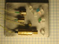
I also added in a power sense diode for the red beam, as the one I am using doesn't have one for some odd reason...
Couple of updates (but I hate to make a triple post...)
1. The glass blocks work great! I glued up the red/uv diodes and even with mild pressure the beams stayed aligned A quick back of the napkin calculation says that I have locked the mirrors down to about 2microns
2. I pulled the plate off the mounting setup and the beam moved about about a mrad (I am trying to keep them aligned to 1/4mrad). Pissed off, I decided to apply a little pressure to the plate, and found that even with a few ounces of prssure I could walk the beam .5mrad.
So, now I am going to have a plate made out of 1/4" thick Al (compared to the .064" pate with 1/4" fins on it) and hope that solves it.
In the mean time, it is time to make some drawings...
..., Tue Apr 17 2007, 06:07AM
Ok, the soldering the lasers down looks like it is going to work well

The first problem I had was that the red laser was solid aluminum, so I had to find a way to attach that without soldering to it. I started by grinding a flat onto it with a dremel tool, which sorta worked, but then I was thinking that it would just be way easier to find a collimator made out of brass. So I started looking, found an old 5mw red laser diode module that had a nice small brass collimator. So I stuck the red diode in, and I was pretty happy.
But then I started thinking about how crappy the blue beam was (let me tell you, it was pretty bad) and figured that just about any collimator would be better than the lens I was using. So I kept searching, and found an old laser pointer, but after dremeling it apart I found out that it was sooo old that is 1mw 650mn diode was in a 9mm can, instead of the 5.6mm one I had. So then I kept looking, and found an old laser level that was soo dim that it was useless (well, when you are only allowed 5mw of power, even with a 630mn diode you aren't going to make very much of a line regardless of how lossy the optics are) so I cracked it open. And to my surprise, there was not 1 laser in there, but 2 identical brass collminators

So in an attempt to try to make the laser look like it wasn't built by a 16 y/o, I decided to use the matching collminatos. So I pulled them apart so that I just had the brass outer part, broke out Andre's solder that has been sitting in a pile for the last 2 years and tinned up a nice big blob on them. If you are insane enough to try this at home, make sure you use flux, lots and lots of flux, and that there are no plastic optics in there...
Then, I needed something to solder them to, so I took a hint from the The first lasers I soldered down and smashed up some burned out to-247 fets (no shortage of those here
 ) and dremeld them square.
Then it was a simple matter of applying some heat, and I ended up not even using a hotplate and just using a 50w solder iron (temp controlled weller) to do the dirty work.
So now I have a well collimated beam, and it has a nice fat plate to glue down (but needs some spacers made up to get them all the same height).
Then there was the problem of the optics, and how I don't have a decent way to attach them to anything. So thinking back to the lightwave 142 laser I got 2nd hand (some moron ripped the highly customised yag and ktp crystals out of it
 ) I remembered that they were glued to a glass post, instead of how I had them attached. Figuring that I have a bunch of glass blocks on hand, I decided to go that route.
So here is the new proposed beam path:

I also added in a power sense diode for the red beam, as the one I am using doesn't have one for some odd reason...
Couple of updates (but I hate to make a triple post...)
1. The glass blocks work great! I glued up the red/uv diodes and even with mild pressure the beams stayed aligned
 A quick back of the napkin calculation says that I have locked the mirrors down to about 2microns
2. I pulled the plate off the mounting setup and the beam moved about about a mrad (I am trying to keep them aligned to 1/4mrad). Pissed off, I decided to apply a little pressure to the plate, and found that even with a few ounces of prssure I could walk the beam .5mrad.
So, now I am going to have a plate made out of 1/4" thick Al (compared to the .064" pate with 1/4" fins on it) and hope that solves it.
In the mean time, it is time to make some drawings...
Re: RGB LASER
Dalus, Wed Apr 25 2007, 08:21PM
Looks quite good. What kind of galvo's are you using to steer the beam around. Just two motors with a mirror mounted at a angle?
Dalus, Wed Apr 25 2007, 08:21PM
Looks quite good. What kind of galvo's are you using to steer the beam around. Just two motors with a mirror mounted at a angle?
Re: RGB LASER
ConKbot of Doom, Thu Apr 26 2007, 11:43AM
Dont think of that as a bad thing nessicarily, you could possibly mount the current plate on the 1/4" plate with heavy stand-offs. Drill and tap threaded holes in the 1/4" plate and use some fine thread(4-40 or maybe even 2-56)set screws to try and precisely adjust the thin plate and the beam alignment.
ConKbot of Doom, Thu Apr 26 2007, 11:43AM
... wrote ...
<snip>
Couple of updates (but I hate to make a triple post...)
1. The glass blocks work great! I glued up the red/uv diodes and even with mild pressure the beams stayed aligned A quick back of the napkin calculation says that I have locked the mirrors down to about 2microns
2. I pulled the plate off the mounting setup and the beam moved about about a mrad (I am trying to keep them aligned to 1/4mrad). Pissed off, I decided to apply a little pressure to the plate, and found that even with a few ounces of prssure I could walk the beam .5mrad.
So, now I am going to have a plate made out of 1/4" thick Al (compared to the .064" pate with 1/4" fins on it) and hope that solves it.
In the mean time, it is time to make some drawings...
<snip>
Couple of updates (but I hate to make a triple post...)
1. The glass blocks work great! I glued up the red/uv diodes and even with mild pressure the beams stayed aligned
 A quick back of the napkin calculation says that I have locked the mirrors down to about 2microns
2. I pulled the plate off the mounting setup and the beam moved about about a mrad (I am trying to keep them aligned to 1/4mrad). Pissed off, I decided to apply a little pressure to the plate, and found that even with a few ounces of prssure I could walk the beam .5mrad.
So, now I am going to have a plate made out of 1/4" thick Al (compared to the .064" pate with 1/4" fins on it) and hope that solves it.
In the mean time, it is time to make some drawings...
Dont think of that as a bad thing nessicarily, you could possibly mount the current plate on the 1/4" plate with heavy stand-offs. Drill and tap threaded holes in the 1/4" plate and use some fine thread(4-40 or maybe even 2-56)set screws to try and precisely adjust the thin plate and the beam alignment.
Re: RGB LASER
..., Fri Apr 27 2007, 06:04AM
To steer the beam I am using the assembly out of some cheep laser projector (you know those ones that have a 5mw red diode that do like circles and stars) I ripped out the old diode and shined the beam from the RGB into it.
As to using set screws to adjust the aluminum, there are just too many axis to keep aligned. There are the 6 translation (x/y for each beam) which 'only' need to be kept to about +/-.02", and then the 6 angular (pitch/yaw for each beam) axis which need to be kept to a simply insane .2mrad.
My solution...
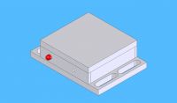
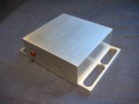
A nice aluminum box ;)
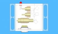
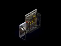
Using the magic of SoldWorks, lets turn that aluminum into glass...
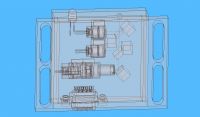
heck, while we are at it lets turn everything clear (yes, I did draw everything in there --save for the LED and DB9 connector that I found online)
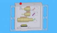
A better angle
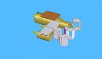
Without all of the extra stuff
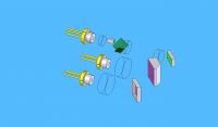
If only this would work in real life...
I still need to add in some screws holding the box together, and find someone that will machine it for me. I have had McFluffin do some work for me, but I thinking I might need to have this sent out, right now ACS is looking pretty good, I can't imagine it taking more than an hour to machine the pieces...
..., Fri Apr 27 2007, 06:04AM
To steer the beam I am using the assembly out of some cheep laser projector (you know those ones that have a 5mw red diode that do like circles and stars) I ripped out the old diode and shined the beam from the RGB into it.
As to using set screws to adjust the aluminum, there are just too many axis to keep aligned. There are the 6 translation (x/y for each beam) which 'only' need to be kept to about +/-.02", and then the 6 angular (pitch/yaw for each beam) axis which need to be kept to a simply insane .2mrad.
My solution...

A nice aluminum box ;)

Using the magic of SoldWorks, lets turn that aluminum into glass...

heck, while we are at it lets turn everything clear (yes, I did draw everything in there --save for the LED and DB9 connector that I found online)

A better angle

Without all of the extra stuff

If only this would work in real life...
I still need to add in some screws holding the box together, and find someone that will machine it for me. I have had McFluffin do some work for me, but I thinking I might need to have this sent out, right now ACS is looking pretty good, I can't imagine it taking more than an hour to machine the pieces...
Re: RGB LASER
Steve Conner, Fri Apr 27 2007, 01:11PM
Too bad SolidWorks can't build the thing for you! :P Anyway, this looks like a great project, I told the guys at my old workplace about it and they were pretty impressed. From the pictures, it looks like you got the beam alignment pretty good, for a few seconds at least
If it were me, I'd align it as best I could and then mess with the collimators to make the laser spots bigger and hide the remaining error.
Steve Conner, Fri Apr 27 2007, 01:11PM
Too bad SolidWorks can't build the thing for you! :P Anyway, this looks like a great project, I told the guys at my old workplace about it and they were pretty impressed. From the pictures, it looks like you got the beam alignment pretty good, for a few seconds at least

If it were me, I'd align it as best I could and then mess with the collimators to make the laser spots bigger and hide the remaining error.

Re: RGB LASER
..., Tue Apr 21 2009, 01:12AM
Well it took a while (almost 2 years to the day) I finally found a way into a machine shop (yay for living at UCSB), and got around to actually manufacturing this beast!
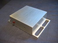
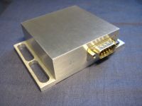
The hand crafted case
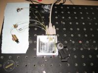
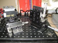
Back on the table ready for some alignment.
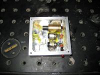
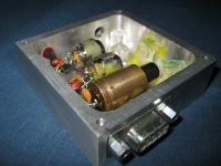
Some nudy shots...
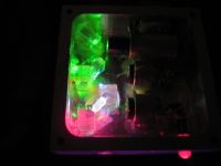
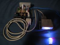
A shot of the lasers running, and the overall system.
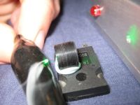
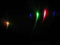
It does burn surprisingly well if focused (between the 3 colors you have a pretty good chance something will absorb considerably, and after it starts to char you get all 3 beams contributing to the power, which right now is only about 150mw due to crappy optics) And a final shot of the beam being refracted off a dvd-rom (my camera doesn't pick up the 405nm hardly at all, so the spot looks yellow)
I am already working on rev3.b, I had issues with the glue on this one, both with the optics drifting around and low power. The optics problem was because I ended up having to use my 3-years-after-the-expiration-date-cure-to-the- consistency-of-chewing-gum uv cure glue due to an incomparability between my curing system and the glue I bought. They seemed pretty solid, but after a week or so the beams drifted to the point where they aren't even touching after more than a few feet, which gives some odd effects which are further compounded by the fact that human eyeballs can't focus on 405nm light so the spot looks pretty funky. The low power was because the final dicro I was using (that was supposed to reflect 650nm red , but transmit 405 violet and 532nm green) was very ill suited to the job and I am loosing about 2/3 of my green and a fair amount of red. Additionally, the super cheep green module I am using (ledshoppe 50mw that costs $25) isn't very happy when at room temperature (it likes to be a bit above room temp) and doesn't perform optimally when heatsinked to the case. None the less it does project a white spot that is on the threshold of painful to look at, and fits in the palm of your hand I am working on making a clone of it that has a more carefully selected green module (possibly on a small tec to keep it happy) and better dicros (I bought a set of ~1" square by 1mm thick filters I plan to dice up off ebay) which should greatly increase the power, and with better glue I should be able to get the alignment a lot better.
I am also build a controller based on an ardiuno microprocessor (for a class at school) that will let me modulate the lasers at a pretty decent speed, and if I get time I will hack in some mirrors to get the projector up and running again.
..., Tue Apr 21 2009, 01:12AM
Well it took a while (almost 2 years to the day) I finally found a way into a machine shop (yay for living at UCSB), and got around to actually manufacturing this beast!


The hand crafted case


Back on the table ready for some alignment.


Some nudy shots...


A shot of the lasers running, and the overall system.


It does burn surprisingly well if focused (between the 3 colors you have a pretty good chance something will absorb considerably, and after it starts to char you get all 3 beams contributing to the power, which right now is only about 150mw due to crappy optics) And a final shot of the beam being refracted off a dvd-rom (my camera doesn't pick up the 405nm hardly at all, so the spot looks yellow)
I am already working on rev3.b, I had issues with the glue on this one, both with the optics drifting around and low power. The optics problem was because I ended up having to use my 3-years-after-the-expiration-date-cure-to-the- consistency-of-chewing-gum uv cure glue due to an incomparability between my curing system and the glue I bought. They seemed pretty solid, but after a week or so the beams drifted to the point where they aren't even touching after more than a few feet, which gives some odd effects which are further compounded by the fact that human eyeballs can't focus on 405nm light so the spot looks pretty funky. The low power was because the final dicro I was using (that was supposed to reflect 650nm red , but transmit 405 violet and 532nm green) was very ill suited to the job and I am loosing about 2/3 of my green and a fair amount of red. Additionally, the super cheep green module I am using (ledshoppe 50mw that costs $25) isn't very happy when at room temperature (it likes to be a bit above room temp) and doesn't perform optimally when heatsinked to the case. None the less it does project a white spot that is on the threshold of painful to look at, and fits in the palm of your hand
 I am working on making a clone of it that has a more carefully selected green module (possibly on a small tec to keep it happy) and better dicros (I bought a set of ~1" square by 1mm thick filters I plan to dice up off ebay) which should greatly increase the power, and with better glue I should be able to get the alignment a lot better.
I am also build a controller based on an ardiuno microprocessor (for a class at school) that will let me modulate the lasers at a pretty decent speed, and if I get time I will hack in some mirrors to get the projector up and running again.
Re: RGB LASER
Conundrum, Tue Apr 21 2009, 06:40PM
cool! btw i have a dead green module here (fried pump diode) but KTP and lens is ok. as i can't get a pump diode is it any use to you?
i also have a LOT of red DVD writer diodes..
A
Conundrum, Tue Apr 21 2009, 06:40PM
cool! btw i have a dead green module here (fried pump diode) but KTP and lens is ok. as i can't get a pump diode is it any use to you?
i also have a LOT of red DVD writer diodes..
A
Re: RGB LASER
..., Tue Apr 21 2009, 08:33PM
I have a pile of dead green pointers too now (the crystals are more or less indestructible, its the diodes that are failure prone) I have been considering rebuilding the, but honestly I can get a brand new one good for 50+mw (the last 2 I ordered were 65mw and 55mw) for $25 why even bother. I might be interested in the dvd-r diodes. Do you know what speed drive they came from? The diodes only start to get powerful when you get to the drives in the 16x-24x zone, a 1x dvdr drive only has a diode good for about 20mw, which at 650nm looks about as bright as .5mw of green...
Cheers
Re: RGB LASER
Conundrum, Tue Apr 21 2009, 09:45PM
they were from older drives. i have one here from a 16x burner (suffered a dose of terminal overload but the diode(s) survived) and a more recent one. also have a sony 20x drive to gut.
-A
Conundrum, Tue Apr 21 2009, 09:45PM
they were from older drives. i have one here from a 16x burner (suffered a dose of terminal overload but the diode(s) survived) and a more recent one. also have a sony 20x drive to gut.
-A
Re: RGB LASER
uzzors2k, Wed Apr 22 2009, 05:57PM
Very nice, your craftsmanship is amazing!
uzzors2k, Wed Apr 22 2009, 05:57PM
Very nice, your craftsmanship is amazing!
Re: RGB LASER
Conundrum, Sun Apr 26 2009, 07:44AM
now build one that fits into a spare lighter RGB using PS3 beam splitters glued together edge on *might* fit, just.
-A
Conundrum, Sun Apr 26 2009, 07:44AM
now build one that fits into a spare lighter
 RGB using PS3 beam splitters glued together edge on *might* fit, just.
-A
Re: RGB LASER
kilovolt, Mon Apr 27 2009, 05:29PM
Wow! great project!! Very nice
kilovolt, Mon Apr 27 2009, 05:29PM
Wow! great project!! Very nice

Re: RGB LASER
..., Mon Apr 27 2009, 06:16PM
Thanks for the kind words guys, and I have more good news!
1. As a part of a class I am taking at UCSB, I am designing a microprocessor based control system that will have a set of galvos (or possible orthogonal spinning mirrors like I used last time) and color control to allow easily projecting multicolor geometric shapes (will be done in early june)
2. I have ordered parts and hope to machine a new case for the second revision that will have proper dichroic mirrors to combine the beams, and some fresh, high quality uv curing adhesive to hold the optics in place which will hopefully keep the beams co-aligned a bit better (hope to get it built in late june)
Re: RGB LASER
..., Wed May 27 2009, 05:45AM
I figure its been long enough I should give you an update:
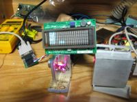
*The controller hardware wise is now just about done, and I am working on an enclosure to finish it off. I have simple code written to control everything, but am planning to let a user upload custom programs (ie, lists of coordinates/color values) that can be selected on the vfd.
*The laser head and galvos are now working in unison (abut somewhat haphazardly since the enclosure is still being built)
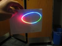
*It projected its first full color image! (well at least the only one that had more than one color at a time)


Re: RGB LASER
kilovolt, Fri May 29 2009, 05:00PM
Very nice work! Especially the full color range of the second picture looks awesome indeed! Well done
Regards kilovolt
kilovolt, Fri May 29 2009, 05:00PM
Very nice work! Especially the full color range of the second picture looks awesome indeed! Well done

Regards kilovolt
Re: RGB LASER
..., Tue Jun 02 2009, 05:06AM
I am just about ready to call this project done, although if I have time tomorrow I am going to build up the rest of the case (although the wires-everywhere-held-together-with-double-sided- tape look seems to be in these days around campus...).
That said, I made a poster with an overview of the system:
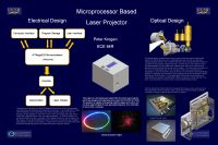
But since the poster is not all that informative...
Overview
This project started out as a curiosity, and quest to build a whitelight laser for a reasonable budget (estimated cost for the laser source is $100). I then chose to use it for a project class (ECE 94R at UCSB) and added set of galvanometers and a controller for the system based on an Arduino microprocessor. The project has probably 200hrs of work in it (150 for the various revisions of the rgb source and 50 for the electrical design and programming), and about $300 in parts that went into it (about $150 in laser diodes--only $60 worth of which are in the final system, $100 for the microprocessor and lcd, $30 for the galvanometers, and $20 in odds and ends).
Design
The design of the projector is highly modularized, and can be easily broken down into the RGB source, Galvanometers, Controller, and Software.
RGB Source:
The RGB source was the hardest of this project to create, and I spent about 2 years working on it on and off. The concept is simple--take red, green, and blue laser diodes, and use dichroic mirrors to combine them into a single beam, which would be sent to the galvanometers.
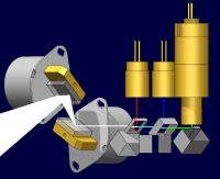
In practice, as the rest of this thread shows, this was not so easy. In order to keep the beams coincident, which is absolutely necessary for proper color mixing, they must be all kept aligned in the x/y/z axis to within about .05" or so, and 0.03mRad in pitch/yaw. This second figure is much harder (that is .1" over 30ft), and is a result of the fact that the divergence of the laser beam is on the order of .2mRad so to keep the beams at least somewhat coincident .03mRad is the max error you can use. To put that in perspective, if one of the edges of the 1/4" square mirrors moves 1/15,000th of an inch, the beam will not be aligned anymore.
That said, to get around this problem I machined a pocket in a 2" square by 1" thick aluminum, and use uv curing epoxy to hold the optics in place:
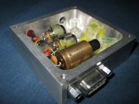
(for more photos of the system, see the post made on 4-20)
The lasers themselves would be to costly to buy from a laser manufacture, so alternate sources of the lasers were found. For the red laser, I used the 650nm laser diode found in a high speed DVD-burner, for the blue laser I decided that the violet laser found in a blu-ray or hd-dvd burner would suffice, and for the green I used a dpss module extracted from a 50mw hand held laser pointer.
Galvanometers:
The purpose of the galvanometers is to position the beam, which allows arbitrary shapes to be 'drawn' using the laser source. Due to cost restrictions, I used a set of stepper motors for the galvanometers. One of the windings was fed with a dc bias which acts as a 'spring' holding the mirror at 45 degrees, and the other winding is fed a signal from the Arduino which will rotate the shaft some angle proportional to the input current. Mounted on the shaft is a mirror, which deflects the beam at some angle, proportional to the rotation of the shaft. Two of these are placed orthogonally, which allows the beam to be positioned at any x,y coordinate on the surface the projector is pointing at, with a scan angle of about 30 degrees (60degrees total scan). However, due to the large momentum of the motors, and lack of feedback, the scan speed is limited to about 1000points/second, and only simple shapes which can easily be represented by a combination of sine and cosine--circles, stars, etc.
Controller:
The controller for the project is electrically quite simple, and most of the grunt work is done in a microprocessor. The hardware timer modules in the Arduino microprocessor are used to generate 5 PWM modulated signals, 3 of which are used to control the laser intensities and 2 are used for the galvanometers. To actually drive the laser diodes a constant current source based on a LM317 voltage regulator is used, and a small mosfet is put in parallel with the laser diode--such that with the mosfet is it will divert current from the laser and blank the laser. The mosfets are driven directly from the PWM outputs of the Arduino, and as a result the lasers are actually being pulse width modulated. However due to the fast PWM outputs of the Arduino (32KHz) and slow scan speeds, this effect is not noticeable in the scanned images. Similarly, to drive the galvanometers, the PWM output from the Arduino is fed through a small amplifier (actually designed for driving mosfets), which is then fed to the galvanometer. Through careful biasing of the galvanometers, it is possible to get both a positive and negative scan angle using this technique, and due to the high momentum of the galvanometers they effectively filter the PWM signal and respond quite linearly.
The microprocessor is an Atmel ATMega328, which has the Arduino bootloader and code written using the Arduino IDE, which controls all of the components of the projector. Due to the limited storage available on the Arduino, an Atmel DataFlash chip was added, which allows about 50 programs that have 4000 points in them (about 4s of continuous scanning) to be stored. Finally, a 4x20 character LCD and simple up/down/select user interface was added to allow programs to be easily selected. Finally, there is a manual mode where the Arduino simply accepts coordinates from an external computer over a RS-232 compliant serial port, which allows for longer and more complex programs to be displayed.
Firmware:
The firmware for the projector is written in a Wiring based program language (the Arduino language), which while not my first choice is what the class was based on. The main loop in the code reads coordinates from the DataFlash and updates the galvanometers and lasers accordingly, then waits a period of time defined by a 5th coordinate saved in DataFlash. Additionally, there a program selector logic, which displays each program's name on the LCD display, and allows the user to scroll through them using an up/down pushbutton. Additionally, there is a random mode which uses a simple random generator, based on a multiply-with-carry random number generator, which displays pseudo-random abstract shapes, a manual mode which projects coordinates received from an external computer via a serial port, or a test mode which displays a simple circle made up of several colors.
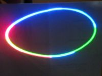

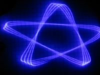
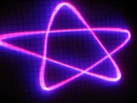
The test pattern (projected on a piece of paper because my camera cannot see the 405nm on a non-florescing surface) and the random data.
Conclusions:
All considered, I learned a lot in making this project, and definitely have plans for a rev 4 (although probably not any time soon). I encourage you to try a project like this, however it is not something that you can throw together in a weekend and have a really decent working project. I really enjoyed the construction process, and the projected images are amazing. The pictures really do not do it justice, the color gamut obtained using 405nm and 650nm is incredible, and computer monitors simply cannot display the range of colors this thing produces. Especially the random mode is very mesmerizing, and it can fill half a room with ever changing patterns of brightly colored lines. I hope you enjoyed reading about it!
..., Tue Jun 02 2009, 05:06AM
I am just about ready to call this project done, although if I have time tomorrow I am going to build up the rest of the case (although the wires-everywhere-held-together-with-double-sided- tape look seems to be in these days around campus...).
That said, I made a poster with an overview of the system:

But since the poster is not all that informative...
Overview
This project started out as a curiosity, and quest to build a whitelight laser for a reasonable budget (estimated cost for the laser source is $100). I then chose to use it for a project class (ECE 94R at UCSB) and added set of galvanometers and a controller for the system based on an Arduino microprocessor. The project has probably 200hrs of work in it (150 for the various revisions of the rgb source and 50 for the electrical design and programming), and about $300 in parts that went into it (about $150 in laser diodes--only $60 worth of which are in the final system, $100 for the microprocessor and lcd, $30 for the galvanometers, and $20 in odds and ends).
Design
The design of the projector is highly modularized, and can be easily broken down into the RGB source, Galvanometers, Controller, and Software.
RGB Source:
The RGB source was the hardest of this project to create, and I spent about 2 years working on it on and off. The concept is simple--take red, green, and blue laser diodes, and use dichroic mirrors to combine them into a single beam, which would be sent to the galvanometers.


In practice, as the rest of this thread shows, this was not so easy. In order to keep the beams coincident, which is absolutely necessary for proper color mixing, they must be all kept aligned in the x/y/z axis to within about .05" or so, and 0.03mRad in pitch/yaw. This second figure is much harder (that is .1" over 30ft), and is a result of the fact that the divergence of the laser beam is on the order of .2mRad so to keep the beams at least somewhat coincident .03mRad is the max error you can use. To put that in perspective, if one of the edges of the 1/4" square mirrors moves 1/15,000th of an inch, the beam will not be aligned anymore.
That said, to get around this problem I machined a pocket in a 2" square by 1" thick aluminum, and use uv curing epoxy to hold the optics in place:


(for more photos of the system, see the post made on 4-20)
The lasers themselves would be to costly to buy from a laser manufacture, so alternate sources of the lasers were found. For the red laser, I used the 650nm laser diode found in a high speed DVD-burner, for the blue laser I decided that the violet laser found in a blu-ray or hd-dvd burner would suffice, and for the green I used a dpss module extracted from a 50mw hand held laser pointer.
Galvanometers:
The purpose of the galvanometers is to position the beam, which allows arbitrary shapes to be 'drawn' using the laser source. Due to cost restrictions, I used a set of stepper motors for the galvanometers. One of the windings was fed with a dc bias which acts as a 'spring' holding the mirror at 45 degrees, and the other winding is fed a signal from the Arduino which will rotate the shaft some angle proportional to the input current. Mounted on the shaft is a mirror, which deflects the beam at some angle, proportional to the rotation of the shaft. Two of these are placed orthogonally, which allows the beam to be positioned at any x,y coordinate on the surface the projector is pointing at, with a scan angle of about 30 degrees (60degrees total scan). However, due to the large momentum of the motors, and lack of feedback, the scan speed is limited to about 1000points/second, and only simple shapes which can easily be represented by a combination of sine and cosine--circles, stars, etc.
Controller:
The controller for the project is electrically quite simple, and most of the grunt work is done in a microprocessor. The hardware timer modules in the Arduino microprocessor are used to generate 5 PWM modulated signals, 3 of which are used to control the laser intensities and 2 are used for the galvanometers. To actually drive the laser diodes a constant current source based on a LM317 voltage regulator is used, and a small mosfet is put in parallel with the laser diode--such that with the mosfet is it will divert current from the laser and blank the laser. The mosfets are driven directly from the PWM outputs of the Arduino, and as a result the lasers are actually being pulse width modulated. However due to the fast PWM outputs of the Arduino (32KHz) and slow scan speeds, this effect is not noticeable in the scanned images. Similarly, to drive the galvanometers, the PWM output from the Arduino is fed through a small amplifier (actually designed for driving mosfets), which is then fed to the galvanometer. Through careful biasing of the galvanometers, it is possible to get both a positive and negative scan angle using this technique, and due to the high momentum of the galvanometers they effectively filter the PWM signal and respond quite linearly.
The microprocessor is an Atmel ATMega328, which has the Arduino bootloader and code written using the Arduino IDE, which controls all of the components of the projector. Due to the limited storage available on the Arduino, an Atmel DataFlash chip was added, which allows about 50 programs that have 4000 points in them (about 4s of continuous scanning) to be stored. Finally, a 4x20 character LCD and simple up/down/select user interface was added to allow programs to be easily selected. Finally, there is a manual mode where the Arduino simply accepts coordinates from an external computer over a RS-232 compliant serial port, which allows for longer and more complex programs to be displayed.
Firmware:
The firmware for the projector is written in a Wiring based program language (the Arduino language), which while not my first choice is what the class was based on. The main loop in the code reads coordinates from the DataFlash and updates the galvanometers and lasers accordingly, then waits a period of time defined by a 5th coordinate saved in DataFlash. Additionally, there a program selector logic, which displays each program's name on the LCD display, and allows the user to scroll through them using an up/down pushbutton. Additionally, there is a random mode which uses a simple random generator, based on a multiply-with-carry random number generator, which displays pseudo-random abstract shapes, a manual mode which projects coordinates received from an external computer via a serial port, or a test mode which displays a simple circle made up of several colors.


The test pattern (projected on a piece of paper because my camera cannot see the 405nm on a non-florescing surface) and the random data.
Conclusions:
All considered, I learned a lot in making this project, and definitely have plans for a rev 4 (although probably not any time soon). I encourage you to try a project like this, however it is not something that you can throw together in a weekend and have a really decent working project. I really enjoyed the construction process, and the projected images are amazing. The pictures really do not do it justice, the color gamut obtained using 405nm and 650nm is incredible, and computer monitors simply cannot display the range of colors this thing produces. Especially the random mode is very mesmerizing, and it can fill half a room with ever changing patterns of brightly colored lines. I hope you enjoyed reading about it!
Re: RGB LASER
c4r0, Tue Jun 02 2009, 08:48AM
That's simply awsome! Where did you get the dichros from? Looks like they are from some optical drives, although on the other hand if you have such lab you certainly have also great dichros :P I have a lot of different dichros harvested from DVD writers but found only one that works quite good for combining 532nm and 650nm. And how do you think is it possible to align all the optics without such sophisticated mechanics like yours or adjustable holders? I set up a quick and dirty RGY laser projector on Saturday. It's so cool that I want to try RGB with 405nm laser now
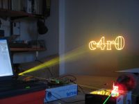
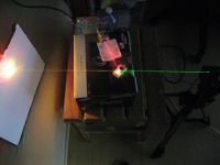
Youtube:
c4r0, Tue Jun 02 2009, 08:48AM
That's simply awsome! Where did you get the dichros from? Looks like they are from some optical drives, although on the other hand if you have such lab you certainly have also great dichros :P I have a lot of different dichros harvested from DVD writers but found only one that works quite good for combining 532nm and 650nm. And how do you think is it possible to align all the optics without such sophisticated mechanics like yours or adjustable holders? I set up a quick and dirty RGY laser projector on Saturday. It's so cool that I want to try RGB with 405nm laser now


Youtube:

Re: RGB LASER
c4r0, Sun Jun 21 2009, 01:47PM
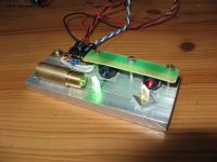
Hello Inspired by your project Peter I also built an RGB laser this weekend and it works quite well. I used dichros from HD DVD and DVD drives, not perfect (especially for green) but works. And BTW do you study at UCSB (I just noticed a logo on the poster)? I'm going to SB on Friday

c4r0, Sun Jun 21 2009, 01:47PM
Hello
 Inspired by your project Peter I also built an RGB laser this weekend and it works quite well. I used dichros from HD DVD and DVD drives, not perfect (especially for green) but works. And BTW do you study at UCSB (I just noticed a logo on the poster)? I'm going to SB on Friday


Re: RGB LASER
..., Sun Jun 21 2009, 10:27PM
That looks great! I am glad the project inspired at least one person
Also, I bought some proper dichroic mirrors that I am going to dice up to the proper size, if you are interested I could probably sell a set of r/g/b dichros for about $10 a piece or $20 for the set.
Can't wait to see it working with the projector!
And yes, i do go to UCSB, but i am not there over the summer. If you look hard enough you should be able to find my poster in harold frank or engineering 2 somewhere, but I am not sure where they put them up or if they are still up.
..., Sun Jun 21 2009, 10:27PM
That looks great! I am glad the project inspired at least one person

Also, I bought some proper dichroic mirrors that I am going to dice up to the proper size, if you are interested I could probably sell a set of r/g/b dichros for about $10 a piece or $20 for the set.
Can't wait to see it working with the projector!
And yes, i do go to UCSB, but i am not there over the summer. If you look hard enough you should be able to find my poster in harold frank or engineering 2 somewhere, but I am not sure where they put them up or if they are still up.
Re: RGB LASER
Conundrum, Sat Aug 08 2009, 03:49PM
hell yeah :) i'll buy a few if they work as described.
btw if its any help I just purchased a load more indium and bismuth metal, so if anyone or ... wants some more low melting point alloy PM me. I am happy to accept swaps as am currently short of several parts including piezoelectric transformers and large area (phone type?) piezo sounders.
Re: RGB LASER
c4r0, Fri Oct 02 2009, 09:41PM
Hi again!
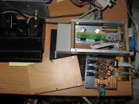
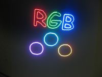
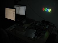
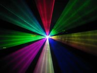
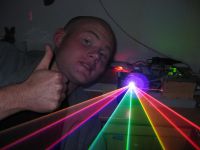
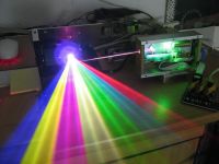
I just have to show it to you guys! I have a flu for a few days so I'm sitting home and trying to not be bored - I finished my RGB laser today. I made a 3-channel LD driver and a wooden casing for the optics and hooked it up to my galvos. It works really well, much better than I thought it would! The only bad thing is that there are different LDs currents setting for white color for eye and camera, so I have to tune it every time I want to take some nice pics or enjoy the effects with naked eye
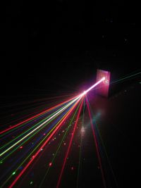
..., does your dichros sell offer still stand? And BTW I spent July in Santa Barbara, haven't seen your poster but I've been on a few parties on del playa! Oh yeah
c4r0, Fri Oct 02 2009, 09:41PM
Hi again!

I just have to show it to you guys! I have a flu for a few days so I'm sitting home and trying to not be bored - I finished my RGB laser today. I made a 3-channel LD driver and a wooden casing for the optics and hooked it up to my galvos. It works really well, much better than I thought it would!
 The only bad thing is that there are different LDs currents setting for white color for eye and camera, so I have to tune it every time I want to take some nice pics or enjoy the effects with naked eye


..., does your dichros sell offer still stand?
 And BTW I spent July in Santa Barbara, haven't seen your poster but I've been on a few parties on del playa! Oh yeah
Re: RGB LASER
MRacerxdl, Fri Oct 02 2009, 10:23PM
WoW thats impressive, I little curious:
The photo shows the laser at air, as like was some smoke or something so, but it doesnt seens to be smoke there. Is there effect visible with naked eye?
MRacerxdl, Fri Oct 02 2009, 10:23PM
WoW thats impressive, I little curious:
The photo shows the laser at air, as like was some smoke or something so, but it doesnt seens to be smoke there. Is there effect visible with naked eye?
Re: RGB LASER
c4r0, Sat Oct 03 2009, 08:14AM
The beams are not wisible at all without smoke. There's a lot of smoke from burning rosin with soldering iron This is the only kind of smoke I have but seems to do it's job pretty well. In closed room, about 3x4 meters, this smoke remains quite long and beams are perfectly visible. The power of this laser is about 50mW total so it's really weak.
c4r0, Sat Oct 03 2009, 08:14AM
The beams are not wisible at all without smoke. There's a lot of smoke from burning rosin with soldering iron
 This is the only kind of smoke I have but seems to do it's job pretty well. In closed room, about 3x4 meters, this smoke remains quite long and beams are perfectly visible. The power of this laser is about 50mW total so it's really weak.
Re: RGB LASER
..., Sat Oct 03 2009, 08:52AM
It depends on the power, over about 100mw is quite visible in air without smoke, with a nice layer of fog even 5mw will show up nicely in a dark room.
@Cr40 - Sorry you missed my poster, I actually haven't seen any proof that the poster ever got put up (and the professor who graded it doesn't recognize me ) but the system is working pretty well. I put my new dicro material in it and the power is up to a solid 100mw or so of white light, unfortunately my camera is completely blind to 405nm so its hard to get good pictures of the system, so here is one taken with my cell phone, and one of the whole projector
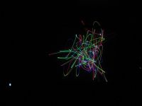
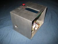
The offer on the dicros still stands, I cut some pieces ~5mm square of the reflect 532 and reflect 405, unfortunately the reflect red dicro had terrible performance (didn't reflect much red), so I am using a mirror salvaged from a DVD drive currently, and using the red diode as the first in the series (so the poor transmission characteristics of the DVD-rom dichro don't' have much of an effect). But if that is ok with you, I can send you the set of 3, although getting it shipped to Poland might end up costing an arm and a leg
..., Sat Oct 03 2009, 08:52AM
It depends on the power, over about 100mw is quite visible in air without smoke, with a nice layer of fog even 5mw will show up nicely in a dark room.
@Cr40 - Sorry you missed my poster, I actually haven't seen any proof that the poster ever got put up (and the professor who graded it doesn't recognize me
 ) but the system is working pretty well. I put my new dicro material in it and the power is up to a solid 100mw or so of white light, unfortunately my camera is completely blind to 405nm so its hard to get good pictures of the system, so here is one taken with my cell phone, and one of the whole projector

The offer on the dicros still stands, I cut some pieces ~5mm square of the reflect 532 and reflect 405, unfortunately the reflect red dicro had terrible performance (didn't reflect much red), so I am using a mirror salvaged from a DVD drive currently, and using the red diode as the first in the series (so the poor transmission characteristics of the DVD-rom dichro don't' have much of an effect). But if that is ok with you, I can send you the set of 3, although getting it shipped to Poland might end up costing an arm and a leg

Re: RGB LASER
..., Sun Oct 04 2009, 06:20PM
Quite nice! I was considering submitting mine, although in my sites current state I am not sure how well it would handle a hackaday-ing (lots of big images on a 2mbit up pipe)
One tip to help reduce the issue that some cameras are not sensitive to 405nm is to project on fluorescing target (like a blank poster board) so that your camera can detect the much more ccd friendly ~460nm light.
Re: RGB LASER
wylie, Tue Oct 06 2009, 07:04PM
... and c4r0:
Too Cool. Just Amazing. Both setups are absolutely beautiful.
I got the idea for my laser-plotting project from hackaday, but it was your two projects that got me to actually make it happen. Kudos, Grats, and Highfives for the both of you.

So, either of you thinking about a next step? How about a new deflection system which would allow you to scan fast enough for raster display. I'm not sure what could provide enough deflection at the speeds required though.
wylie, Tue Oct 06 2009, 07:04PM
... and c4r0:
Too Cool. Just Amazing. Both setups are absolutely beautiful.
I got the idea for my laser-plotting project from hackaday, but it was your two projects that got me to actually make it happen. Kudos, Grats, and Highfives for the both of you.
and the professor who graded it doesn't recognize meThat's sad. Did he even look at the project, or do they just rubber stamp their grades? Seriously, was there a cooler project anywhere on campus that year? Unless you had classmates working on breakeven-capable fusion reactors, or maybe commercially viable spacecraft....

So, either of you thinking about a next step? How about a new deflection system which would allow you to scan fast enough for raster display. I'm not sure what could provide enough deflection at the speeds required though.
Re: RGB LASER
lpfthings, Wed Oct 07 2009, 08:58AM
I have also been thinking about this, the best way I see would be to use 2 small hexagonal mirrors mounted on fast-ish motors, they would give you a XY field, then you just have to modulate the lasers fast enough. THe problem is, you would have to modulate the lasers a lot faster than the little green module can handle. It is DPSS, and the conversion process isn't as fast as diodes, so you would have to use a green laser with TEC cooling on both crystals to get fast enough modulation without jellybeaning (Term used when the laser doesn't have time to turn on and stabilize before it's switched off again).
lpfthings, Wed Oct 07 2009, 08:58AM
wylie wrote ...
How about a new deflection system which would allow you to scan fast enough for raster display. I'm not sure what could provide enough deflection at the speeds required though.
How about a new deflection system which would allow you to scan fast enough for raster display. I'm not sure what could provide enough deflection at the speeds required though.
I have also been thinking about this, the best way I see would be to use 2 small hexagonal mirrors mounted on fast-ish motors, they would give you a XY field, then you just have to modulate the lasers fast enough. THe problem is, you would have to modulate the lasers a lot faster than the little green module can handle. It is DPSS, and the conversion process isn't as fast as diodes, so you would have to use a green laser with TEC cooling on both crystals to get fast enough modulation without jellybeaning (Term used when the laser doesn't have time to turn on and stabilize before it's switched off again).
Re: RGB LASER
..., Wed Oct 07 2009, 06:29PM
I did think about it for a little while, I would probably use an external modulator for the green, a polygonal mirror for the fast axis and a scanner of some sort for the slow axis (to avoid needing to sync up two polygonal mirrors). The issue with raster scanning is that you really do not have a lot of power to play with, a 'real' projector will have 10-1000w of light power to start with, so with a laser that has perhaps .1w you really have a lot going against you. The real benefit to using a vector scanner system is that you can make the best use of the limited power you have available, so you can get nice bright outlines with a small amount of power.
As to my project, there were TAs that watched our presentations, the professor was supposed to come but noted that he has a family who is more important to him than us My project was probably one of the more interesting of the bunch, mainly because I knew what I was doing, had already finished the laser head before starting, and was willing to spend time working on it. The next runner up was probably the person who took a clock face and replaced the times with the dining commons on campus, then used a ton of processing to scrape the menus provided by the dining commons and a list of his favorite foods to point to the dining commons that he should go to
In the mean time, I am working on a higher power laser, it all goes well I should be able to get 100w of IR laser power
..., Wed Oct 07 2009, 06:29PM
I did think about it for a little while, I would probably use an external modulator for the green, a polygonal mirror for the fast axis and a scanner of some sort for the slow axis (to avoid needing to sync up two polygonal mirrors). The issue with raster scanning is that you really do not have a lot of power to play with, a 'real' projector will have 10-1000w of light power to start with, so with a laser that has perhaps .1w you really have a lot going against you. The real benefit to using a vector scanner system is that you can make the best use of the limited power you have available, so you can get nice bright outlines with a small amount of power.
As to my project, there were TAs that watched our presentations, the professor was supposed to come but noted that he has a family who is more important to him than us
 My project was probably one of the more interesting of the bunch, mainly because I knew what I was doing, had already finished the laser head before starting, and was willing to spend time working on it. The next runner up was probably the person who took a clock face and replaced the times with the dining commons on campus, then used a ton of processing to scrape the menus provided by the dining commons and a list of his favorite foods to point to the dining commons that he should go to
In the mean time, I am working on a higher power laser, it all goes well I should be able to get 100w of IR laser power

Print this page