
Induction heater: hybrid drivers strange behaviour
Ramonn, Sun Nov 29 2015, 08:43PMHello IH family: Trying to follow the Campbell project, I built the hybrid drivers for the IGBT’s, (M57962L driver and VLA106-15242 DC-DC converter) but I’ve found a strange behaviour in them: the output signals they delivery to the gates is wider than the input ones. It seems those drivers delivery the signals referenced to the negative cycle of the input pulse… which is always under the theory 50%, so both channels of igbts are shorted for a time, see pictures. I’m scared to feed the bricks under that short-circuit… I’ve tried with different oscillators: the mindchallenger PLL, another one based on a IC3525, other on the pwm494, also a 555 timer, all with and without gate transformers, etc. Problem persists… Even using the 494 as pwm, I’ve seen the narrower is the input, the wider the output. Datasheets don’t clarify anything… I’ve tried to contact to Mr. Campbell, but, unfortunately it seems he is no longer active in IH world… and what is worse, will never finish his wonderful ReactorForge project. So, I come here hopping someone else has worked or somehow involved to those hybrid drivers, for any help if ever found the same problem. Thank you in advance..

Re: Induction heater: hybrid drivers strange behaviour
Ramonn, Sun Nov 29 2015, 08:47PM


Frequency is about 70Khz
Ramonn, Sun Nov 29 2015, 08:47PM


Frequency is about 70Khz
Re: Induction heater: hybrid drivers strange behaviour
parasole, Fri Dec 04 2015, 05:59PM
Hi Ramon,
did you follow Powerex AN?

I am going to use similar product (VLA567-01R), already in my hands but did not come yet to any testing...
parasole, Fri Dec 04 2015, 05:59PM
Hi Ramon,
did you follow Powerex AN?
I am going to use similar product (VLA567-01R), already in my hands but did not come yet to any testing...
Re: Induction heater: hybrid drivers strange behaviour
Ramonn, Sun Dec 06 2015, 11:04PM
Hello Parasole;
Yes I read that datasheet, and above all I stuffed that hybrid drivers following strictly Campbell's BOM and pcb layout... What I find hard to believe is, as I said, the out pulses provided by this drivers are WIDER than the input ones, the signal from an oscillator. So it always will be a shortcircuit time. Maybe it works as a kind of "oposite", taking the negative cicle of the wave to drive the gate signals. In this case, I dont't know how to generate a wave with wider negative pulses... Yours is some different to mine; test it in a breadboard and tell me the result... Thank you.
Re: Induction heater: hybrid drivers strange behaviour
parasole, Mon Dec 07 2015, 08:35PM
hm, looked once again to your signals, did you try to change the duty cycle for your signal? Try for example 30/70 instead of 50%... Then you may adjust your input signal duty cycle to the desired dead time interval, I believe this is the way...
From data sheet it looks like the rise time and propagation time could be different within their limits, then no surprise that there might be differences in output signal:
“L-H†Propagation Time tPLH VI = 0 to 4V, Tj ± 85°C — 1.0 1.5 µs
“L-H†Rise Time tr VI = 0 to 4V, Tj ± 85°C — 0.6 1.0 µs
“H-L†Propagation Time tPHL VI = 0 to 4V, Tj ± 85°C — 1.0 1.5 µs
“H-L†Rise Time tr VI = 0 to 4V, Tj ± 85°C — 0.4 1.0 µs
parasole, Mon Dec 07 2015, 08:35PM
Ramonn wrote ...
What I find hard to believe is, as I said, the out pulses provided by this drivers are WIDER than the input ones
What I find hard to believe is, as I said, the out pulses provided by this drivers are WIDER than the input ones
hm, looked once again to your signals, did you try to change the duty cycle for your signal? Try for example 30/70 instead of 50%... Then you may adjust your input signal duty cycle to the desired dead time interval, I believe this is the way...
From data sheet it looks like the rise time and propagation time could be different within their limits, then no surprise that there might be differences in output signal:
“L-H†Propagation Time tPLH VI = 0 to 4V, Tj ± 85°C — 1.0 1.5 µs
“L-H†Rise Time tr VI = 0 to 4V, Tj ± 85°C — 0.6 1.0 µs
“H-L†Propagation Time tPHL VI = 0 to 4V, Tj ± 85°C — 1.0 1.5 µs
“H-L†Rise Time tr VI = 0 to 4V, Tj ± 85°C — 0.4 1.0 µs
Re: Induction heater: hybrid drivers strange behaviour
Ramonn, Tue Dec 08 2015, 11:05AM
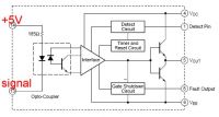
Hello; having another look to the paper, I've noticed that the built-in optocoupler seems really working referenced to negative cycle, see picture... pin 14 is constant 5V supply, and pin 13 is driver signal, so the opto only will be 'on' during negative cycle. I've tried a pwm pulse, it confirms that: decreasing the duty increases the output!! I'm thinking to change polarity; 5V to pin 13 and signal to pin 14. Let's see what happens...
Ramonn, Tue Dec 08 2015, 11:05AM
Hello; having another look to the paper, I've noticed that the built-in optocoupler seems really working referenced to negative cycle, see picture... pin 14 is constant 5V supply, and pin 13 is driver signal, so the opto only will be 'on' during negative cycle. I've tried a pwm pulse, it confirms that: decreasing the duty increases the output!! I'm thinking to change polarity; 5V to pin 13 and signal to pin 14. Let's see what happens...

Re: Induction heater: hybrid drivers strange behaviour
parasole, Tue Dec 08 2015, 05:36PM
 Actually it is not negative, at the input it is logical level and there is high (Vcc) and low level (ground). Than yes, while having feeding positive voltage supply, signal side active level is low, and this is all you need to know, just provide low active with requited duration. Obviously, you may ground pin 13 than feeding high active level to pin 14 will do the job, just make sure you will provide enough current, usually active high is having lower load capability than active low, just due of the way output stage is done on ICs...
parasole, Tue Dec 08 2015, 05:36PM
Ramonn wrote ...
Hello; having another look to the paper, I've noticed that the built-in optocoupler seems really working referenced to negative cycle, see picture... pin 14 is constant 5V supply, and pin 13 is driver signal, so the opto only will be 'on' during negative cycle.
Now I got what do you mean by negative cycle Hello; having another look to the paper, I've noticed that the built-in optocoupler seems really working referenced to negative cycle, see picture... pin 14 is constant 5V supply, and pin 13 is driver signal, so the opto only will be 'on' during negative cycle.
Actually it is not negative, at the input it is logical level and there is high (Vcc) and low level (ground). Than yes, while having feeding positive voltage supply, signal side active level is low, and this is all you need to know, just provide low active with requited duration. Obviously, you may ground pin 13 than feeding high active level to pin 14 will do the job, just make sure you will provide enough current, usually active high is having lower load capability than active low, just due of the way output stage is done on ICs...Re: Induction heater: hybrid drivers strange behaviour
Ramonn, Fri Dec 11 2015, 07:12PM
Yes, I said it wrongly!, both my english and electronics knowledge are small, :( meant "low level".... I changed pins as I said, but as I start from the simple oscillator output from the PLL 4046 chip, I have to "duplicate" it, with a transformer, obtaining two signals to feed the two pairs of IGBT gates (180 degrees de-phased), what leads me to the original problem: overlapping open-times for the igbt's. But I've discovered that decreasing de voltage of the pcb, decreases the overlapping, or putting a resistor in one input of the transformer. But doing this the signal is weak and jitters... I'm going to get mad!!.
-Have you tested yours?
Re: Induction heater: hybrid drivers strange behaviour
parasole, Sun Dec 13 2015, 07:02PM
Since you use 4046, I would add an comparator for duty cycle adjustment, then one more invertor for having 180 degree bridge signals...
Another option would be wiring few logic elements and introduce dead time... Do some google search, there are plenty of examples how to do this...
I don't know when I will test my drivers, still to busy... From other side I would not have this issue since I am intending to use controller and will have full control over my driving signals...
Re: Induction heater: hybrid drivers strange behaviour
Ramonn, Wed Dec 16 2015, 12:40PM
Ok, thanks for advises, and good luck in your project. If you get succes in that controller, will share it? As I understand, the 4046 PLL never has a good or total apliance for our DIY induction heaters, just getting bigger our boxes of blown transistors
Ramonn, Wed Dec 16 2015, 12:40PM
Ok, thanks for advises, and good luck in your project. If you get succes in that controller, will share it? As I understand, the 4046 PLL never has a good or total apliance for our DIY induction heaters, just getting bigger our boxes of blown transistors
Re: Induction heater: hybrid drivers strange behaviour
parasole, Sun Dec 20 2015, 09:38AM
well, every thing is possible, it just require some more engineering...
Did you check Wolfram thread? He use as the basis same PLL however different phase detector which is found to be much more stable for resonant circuits...
With regard to Campbell project, in one of his intermediate project he used an micro controller inserted in the PLL analog control loop, that variant in my opinion is quite interesting for its simplicity and more possibilities added by MC use. You may try to combine new phase detector with Campbel MC variant, the code he provided is very easy to understand and apply some tuning if required.
Re: Induction heater: hybrid drivers strange behaviour
Wolfram, Sun Dec 20 2015, 10:41PM
The new phase detector makes it possible to make a universally stable PLL, but also some other points are important to get a working system. This turned out to be really tricky, and I understand why so many people have trouble with PLLs. Working with a PLL induction heater has been my main hobby project for one year now, and I'm finally feeling like I have everything under control. The main important points are:
The VCO range needs to be limited to a range where the bridge and gate drivers work correcly and without being damaged. The VCO does not need to be completely linear, but there should be no abrupt frequency steps when the VCO control input is changed (this is a problem with some types of 74HC4046 if the VCO control voltage goes outside the acceptable range, which is typically 1 to 4 volts when the supply is 5 volts)
The current (or voltage) feedback signal needs to be stable for the whole range of expected VCO frequencies and bridge voltages, and the phase shift between the actual current and the measured current needs to be minimal and independent of primary current. It is easy to get a good phase feedback signal when the tank is at resonance, but it is more difficult to get a feedback signal with minimal additional phase shift when the VCO is running far from the resonant frequency. Limiting the VCO range makes this simpler.
As already discussed, the phase detector needs to work correctly for the whole range of phase shifts in normal operation. It is not possible to make a totally stable solution with any of the normal phase detectors, and I have made a separate thread about this:
It is a bit simpler with a microcontroller, because you can use clever algorithms to limit the VCO range to around the resonant frequency. I prefer to do it with pure logic to get a complete understanding of the system, then I can simplify it later.
Re: Induction heater: hybrid drivers strange behaviour
Ramonn, Mon Dec 28 2015, 05:00PM
Hi friends; Thanks for posts; but as I said before, regretably my knowledge of electronics is so small to get your level :( I've read nearly everything about it in the net, and also tried to build some of them, but as I need a high power unit for my work, finally found that Campbell one and decieded to follow it, seeing it has few components, and awaiting the day he released his total project, so I could buy him the "difficult-to-build-parts". No day so far. So I'm trying to be back to previous tries, as that board in my first picture, belonging to mindchallenger.com project, used in PLL and manual mode because I have not the code for the uP, and waiting till I make it work in that way, and then asking for someone to write a code for it. So complicated, yeah, depending on other's work... But sure you can understand how induction heating rises fascination in diyers!, and when the beast bites you, difficult getting rid of...
About my first problem, I will use a gate transformer to duplicate and invert the signals, and connect it to M57962L drivers as if they were usual optocouplers; not feeding the input pins with constant 5V. Hope it works, will keep informed.
Happy new year!!
Re: Induction heater: hybrid drivers strange behaviour
parasole, Thu Dec 31 2015, 09:44PM
Ramonn, I don't think you need transformers to drive M57962L, they are intended to exclude transformers and to provide easy way for bridge control. I would suggest to use ether or transformer or M57962L, latest being a better choice. However, in this case you need to do some more preparation for driving signal, and for better understanding I would suggest once again to investigate Wolfram schematic...
Happy New Year!
Re: Induction heater: hybrid drivers strange behaviour
parasole, Mon Jan 04 2016, 03:09PM
Hi again Ramon,
I am working now on the hybrid IH solution, and thought the very same chip for bridge control may help you to solve your issues, just switch to use TI UC3875/3879, it is a ready full bridge phase shift controller which easily could be included in PLL loop. In my case I want to use ADPLL, however I don't see any problems in using classical phase detector with filtered output to tune up internal oscillator of uc3875, in this case you will have full solution for bridge control with PLL frequency tracking. In my opinion this combo is much better than 4046 with all additional logic for bridge control, with lots of additional functions which would be complex to implement around 4046...
Another way is to use bridge current as control input for frequency adjustment to the resonant point (as on picture), I have an academic paper on this, let me know if you want it.

Re: Induction heater: hybrid drivers strange behaviour
Ramonn, Tue Jan 05 2016, 03:40PM
Thanks Parasole! -Later days I've solved my first problem about the overlapped signals; faling using transformer, I discarded it and tried an IC 4013 flip flop to duplicate and oposite the signals; firstly same problem appeared, but I discovered that putting a resistor in the outputs, and another one in the 4013 voltage supply, the signals decreased in period time, or duty cycle, even getting some "deadtime" between signals... so playing a little with resistor values I found the appropiate ones. Now I have to test it all connected to the tank and workcoil.
-Yes I read the very interesting Wolfram threads and posts, but as I said, that level is still difficult to reach to me; first I want to explore the limits in the project I have built and followed, and if failing (most probably!! ;) considere migrating to Wolfram schema, or to anyone's proved ok...
-Also the UC3875 you point seems nice, I'll let it in consideration for those future tries.
-About that paper you say, ok if you share it to me, but I'm affraid its complexity will be again out of my knowledge reach...
Re: Induction heater: hybrid drivers strange behaviour
Josh Campbell, Sat Dec 16 2017, 07:50PM
Hello Ramonn. First off my apologies for not getting back to you. Over the past few years whenever I would receive an email about Induction Heaters (which was very often) I would flag it so I could respond in a timely manner. However, I missed yours. I just searched your name and boom there it was, it never got flagged! :( Thank goodness for the awesome minds on this forum!
Are you still doing work on your IH?
I should mention that the adjustments possible when using the power stage controller (AT90PWMXXX) are very important when used with a driver of this type. Coming from the world of gate transformers and delay logic no longer applies, it must all be in code now. Reading your OP the first thought that came to mind was, I wonder if he was just had his logic reversed, active high vs low. Which would mean the duty cycle adjustments were on the wrong side of the signal. I doubt that was the case because that seems too obvious especially if you are scoping it.
Anyway hope all is well and I am continuing work on the ReactorForge!
Print this page