
Building my first SSTC. Need some pointers
SK1701, Tue Aug 11 2015, 12:17PMHello everyone. I am a high school student in India and I've been really interested in Tesla coils ever since I got to sit in the Faraday cage during the Tesla Coil demo at the Science Center Singapore. I never was able to build one due to the lack of availability of parts like NSTs and high voltage caps for the MMC. I recently discovered solid state Tesla coils and realised they fit my requirements very well. The parts are relatively cheap as well as easily available here. To get started, I built a simple slayer exciter with one transistor. Now I want to build a full blown SSTC based on the Kaizer SSTC 1 or 2.
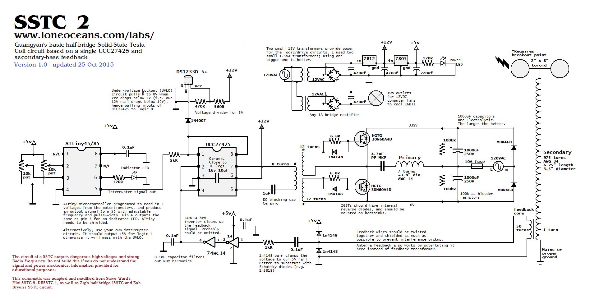
I want to thank Mr. Mads Barnkob for the excellent writeup as well as the schematic. I also want to thank Loneoceans. His website made it so much easier for me to understand the working of an SSTC.
So far I have built the logic circuit for this coil. I'm waiting for access to an oscilloscope so I can test it (shouldn't be long). I got the UCC3732x ICs as free samples from Texas Instruments (thanks!) and now I need to build the bridge as well as the actual coil.
Now that my long winded introduction is done. These are my questions for now:
1. Safety. I wanted to ask about some of the safety concerns around this coil (apart from more common stuff like ozone production, high voltages around the bridge rectifier etc.)
2. I've managed to lay my hands on some 3mm dia plastic conduit. Can I cover it with aluminium tape and use it as a top load (with an appropriate breakout point)?
3. I've ordered these for the gate drive transformer. Will they work? I haven't been able to find a local source for large ferrite toroids.
4. How do I avoid blowing the fuses at home? The secondary goes to mains ground right?
Thank you.
Re: Building my first SSTC. Need some pointers
dexter, Tue Aug 11 2015, 12:36PM
3.you need a high permeability core 3C90 or higher
you should avoid powder iron or similar cores (the listing does not give much details only "green iron")
you don't rly need such a big core
dexter, Tue Aug 11 2015, 12:36PM
SK1701 wrote ...
3. I've ordered these for the gate drive transformer. Will they work? I haven't been able to find a local source for large ferrite toroids.
3. I've ordered these for the gate drive transformer. Will they work? I haven't been able to find a local source for large ferrite toroids.
3.you need a high permeability core 3C90 or higher
you should avoid powder iron or similar cores (the listing does not give much details only "green iron")
you don't rly need such a big core
Re: Building my first SSTC. Need some pointers
loneoceans, Tue Aug 11 2015, 05:48PM
Hello and welcome to the forum!
First off just wanted to say that I'm glad that you were inspired by the big coil in Singapore (I'm from Singapore!). Also glad that you found my page useful. Anyway, answering your questions:
1. What were the safety concerns you had? One of the most dangerous aspects with a small coil like this and for a beginning coiler is that you'll be using the mains as the power source for the coil. This can be extremely dangerous, so I urge you to do a proper job with the wiring and ask someone who has more experience if you're not sure about anything. The capacitors in the main DC bus are also extremely dangerous when charged up, so be sure to add some sort of bleeder resistor across. Also, adding a fuse usually helps as well in case you have some transistor failure.
2. Are you talking about the toroid? Yes you can use flexible PVC ducting as a toroid when covered with aluminium tape. See my other earlier pages (e.g. Tesla Coil 1 and 2) on how I made my aluminium tape toroids.
3. The toroid you linked are powered iron toroids and not ferrite toroids, and they will not work. You'll need ferrite cores for the GDT, and my SSTC 2 page describes an easy way to find out if the core is suitable. Do you have access to say Digikey, Mouser, Element14, RS electronics or Farnell online? If so I can recommend a few cores which would work.
4. Ideally the bottom of the secondary should go to a dedicated ground (e.g. copper rod literally hammered into the ground). However, if the grounding in your house is good and you have a small coil, it's usually ok to ground it to mains ground. This hasn't got anything to do with the fuses in your home, but if your wall socket is one of the newer GFI sockets which sense ground current, then you cannot use those since the return current will cause the GFI to turn off power.
Feel free to ask more questions and good luck with your coil. :)
loneoceans, Tue Aug 11 2015, 05:48PM
SK1701 wrote ...
Hello everyone. I am a high school student in India and I've been really interested in Tesla coils ever since I got to sit in the Faraday cage during the Tesla Coil demo at the Science Center Singapore. I never was able to build one due to the lack of availability of parts like NSTs and high voltage caps for the MMC. I recently discovered solid state Tesla coils and realised they fit my requirements very well. The parts are relatively cheap as well as easily available here. To get started, I built a simple slayer exciter with one transistor. Now I want to build a full blown SSTC based on the Kaizer SSTC 1 or 2.
I want to thank Mr. Mads Barnkob for the excellent writeup as well as the schematic. I also want to thank Loneoceans. His website made it so much easier for me to understand the working of an SSTC.
So far I have built the logic circuit for this coil. I'm waiting for access to an oscilloscope so I can test it (shouldn't be long). I got the UCC3732x ICs as free samples from Texas Instruments (thanks!) and now I need to build the bridge as well as the actual coil.
Now that my long winded introduction is done. These are my questions for now:
1. Safety. I wanted to ask about some of the safety concerns around this coil (apart from more common stuff like ozone production, high voltages around the bridge rectifier etc.)
2. I've managed to lay my hands on some 3mm dia plastic conduit. Can I cover it with aluminium tape and use it as a top load (with an appropriate breakout point)?
3. I've ordered these for the gate drive transformer. Will they work? I haven't been able to find a local source for large ferrite toroids.
4. How do I avoid blowing the fuses at home? The secondary goes to mains ground right?
Thank you.
Hello and welcome to the forum!
First off just wanted to say that I'm glad that you were inspired by the big coil in Singapore (I'm from Singapore!). Also glad that you found my page useful. Anyway, answering your questions:
1. What were the safety concerns you had? One of the most dangerous aspects with a small coil like this and for a beginning coiler is that you'll be using the mains as the power source for the coil. This can be extremely dangerous, so I urge you to do a proper job with the wiring and ask someone who has more experience if you're not sure about anything. The capacitors in the main DC bus are also extremely dangerous when charged up, so be sure to add some sort of bleeder resistor across. Also, adding a fuse usually helps as well in case you have some transistor failure.
2. Are you talking about the toroid? Yes you can use flexible PVC ducting as a toroid when covered with aluminium tape. See my other earlier pages (e.g. Tesla Coil 1 and 2) on how I made my aluminium tape toroids.
3. The toroid you linked are powered iron toroids and not ferrite toroids, and they will not work. You'll need ferrite cores for the GDT, and my SSTC 2 page describes an easy way to find out if the core is suitable. Do you have access to say Digikey, Mouser, Element14, RS electronics or Farnell online? If so I can recommend a few cores which would work.
4. Ideally the bottom of the secondary should go to a dedicated ground (e.g. copper rod literally hammered into the ground). However, if the grounding in your house is good and you have a small coil, it's usually ok to ground it to mains ground. This hasn't got anything to do with the fuses in your home, but if your wall socket is one of the newer GFI sockets which sense ground current, then you cannot use those since the return current will cause the GFI to turn off power.
Feel free to ask more questions and good luck with your coil. :)
Re: Building my first SSTC. Need some pointers
SK1701, Wed Aug 12 2015, 01:09AM
Thank you for the replies. I really appreciate the help.
@loneoceans your website is a great inspiration. It has some great content. Did you by any chance build the smaller coil in the Science Center? The musical one? Is that your DRSSTC 2
1. What would be an appropriate value for the fuse? I will be using a 10A bridge rectifier so can I go for a 12-15A fuse? I need to calculate the value of the bleeder resistor but I am not sure of the value of the capacitor I have. I got it from a local electronics store and it is pretty big. It is in a white case with no markings. I also know that it can take mains voltages (I tested it and it creates a nice big spark). I have to ask them what the capacity is and decide whether or not to risk using such a spurious part. What sort of discharge time should I factor in to the calculation for the bleeder resistor?
2. Thanks. That is really helpful. I will build my toroid like that then. Is there any particular advantage of using 2 toroids? My toroid seems smaller than the one used in the Kaizer so is there anything I need to be aware of?
3. If you can recommend an element14 or Digikey part number I may be able to get it from here or a local digikey dealer (ince shipping from the US is too expensive otherwise). The core should be able to accommodate up to 5 coils on it since I may go with a full bridge configuration.
4. I don't know if will be able to ground it outside, but I can definitely wire it to mains ground. My wall sockets definitely do not have GFI, so that shouldn't be a problem.
Thank you.
Re: Building my first SSTC. Need some pointers
loneoceans, Wed Aug 12 2015, 05:24PM
I'm not sure which coil you saw but I've made two musical coils and they're currently in the Science Centre.
1. I don't know what sort of power socket you are using, but if you're using a 13A socket you can use a 13A or 10A fuse. What I'm more concerned about is your capacitor - what sort of capacitor do you have? Do you have a picture of it? I would strongly advice you NOT to connect your cap to the mains because it can explode! What capacitor are you referring to - the bus capacitor?
2. There's no need to use 2 toroids. I used two for some of my coils because the capacitance of the first toroid wasn't enough, or I had some spare toroids lying around. Or if you want a different look to your coil. 3 toroids would be fine as well. Otherwise I'll just use one :)
3. Here are two cores which will should work great. You can buy a few and use them for future coils too.

4. Mains ground should be ok for small coils.
loneoceans, Wed Aug 12 2015, 05:24PM
SK1701 wrote ...
Thank you for the replies. I really appreciate the help.
@loneoceans your website is a great inspiration. It has some great content. Did you by any chance build the smaller coil in the Science Center? The musical one? Is that your DRSSTC 2
1. What would be an appropriate value for the fuse? I will be using a 10A bridge rectifier so can I go for a 12-15A fuse? I need to calculate the value of the bleeder resistor but I am not sure of the value of the capacitor I have. I got it from a local electronics store and it is pretty big. It is in a white case with no markings. I also know that it can take mains voltages (I tested it and it creates a nice big spark). I have to ask them what the capacity is and decide whether or not to risk using such a spurious part. What sort of discharge time should I factor in to the calculation for the bleeder resistor?
2. Thanks. That is really helpful. I will build my toroid like that then. Is there any particular advantage of using 2 toroids? My toroid seems smaller than the one used in the Kaizer so is there anything I need to be aware of?
3. If you can recommend an element14 or Digikey part number I may be able to get it from here or a local digikey dealer (ince shipping from the US is too expensive otherwise). The core should be able to accommodate up to 5 coils on it since I may go with a full bridge configuration.
4. I don't know if will be able to ground it outside, but I can definitely wire it to mains ground. My wall sockets definitely do not have GFI, so that shouldn't be a problem.
Thank you.
I'm not sure which coil you saw but I've made two musical coils and they're currently in the Science Centre.
1. I don't know what sort of power socket you are using, but if you're using a 13A socket you can use a 13A or 10A fuse. What I'm more concerned about is your capacitor - what sort of capacitor do you have? Do you have a picture of it? I would strongly advice you NOT to connect your cap to the mains because it can explode! What capacitor are you referring to - the bus capacitor?
2. There's no need to use 2 toroids. I used two for some of my coils because the capacitance of the first toroid wasn't enough, or I had some spare toroids lying around. Or if you want a different look to your coil. 3 toroids would be fine as well. Otherwise I'll just use one :)
3. Here are two cores which will should work great. You can buy a few and use them for future coils too.
4. Mains ground should be ok for small coils.
Re: Building my first SSTC. Need some pointers
SK1701, Thu Aug 13 2015, 04:29PM
1. Yes, it is the bus capacitor. The place where I bought it 'demonstrated' it by plugging it into the mains for less than a second and then shorting the leads to make a pretty big spark (I have successfully replicated this so I'm sure the cap can take the voltage). Here is a photo next to a spool of solder for scale:

Unfortunately, I can't tell the polarity of this cap as it has no markings on it.
My house has 5A and 15A sockets. I will be running it off the 15A socket. I found a 15A fuse. Will it work? The KAizer webpage mentions that a 27K bleeder resistor was used. Can I use 2 10K 10 Watt wirewound resistors in series?
2. I will either use the plastic conduit method or the method described here.
3. Unfortunately, the Digikey distributor I was planning to order from appears defunct. I will search for other distributors, but would any one of these toroids work?
SK1701, Thu Aug 13 2015, 04:29PM
1. Yes, it is the bus capacitor. The place where I bought it 'demonstrated' it by plugging it into the mains for less than a second and then shorting the leads to make a pretty big spark (I have successfully replicated this so I'm sure the cap can take the voltage). Here is a photo next to a spool of solder for scale:
Unfortunately, I can't tell the polarity of this cap as it has no markings on it.
My house has 5A and 15A sockets. I will be running it off the 15A socket. I found a 15A fuse. Will it work? The KAizer webpage mentions that a 27K bleeder resistor was used. Can I use 2 10K 10 Watt wirewound resistors in series?
2. I will either use the plastic conduit method or the method described here.
3. Unfortunately, the Digikey distributor I was planning to order from appears defunct. I will search for other distributors, but would any one of these toroids work?
Re: Building my first SSTC. Need some pointers
Justin, Thu Aug 13 2015, 05:19PM
B64290L674X830 Should work well.
Justin, Thu Aug 13 2015, 05:19PM
B64290L674X830 Should work well.
Re: Building my first SSTC. Need some pointers
dexter, Thu Aug 13 2015, 06:45PM
that cap looks like a motor starter cap...
it can work as a buss cap but the capacity is to small... at best it has 40uF
dexter, Thu Aug 13 2015, 06:45PM
that cap looks like a motor starter cap...
it can work as a buss cap but the capacity is to small... at best it has 40uF
Re: Building my first SSTC. Need some pointers
loneoceans, Thu Aug 13 2015, 08:02PM
I don't understand why your electronics shop would do that - that's extremely dangerous. In any case, that's like what Dexter said likely to be a motor starting film capacitor. It's too small to be used as a bus cap; you'll need a proper electrolytic capacitor. You need to understand what the bleeder resistor is for and size it appropriately. 20K 20W will work fine.
May I recommend you begin with a simpler circuit first such as a high voltage Flyback circuit :) There are lots of pages online including my page which outline some simpler circuits to get started. This will help you out in the long run when working on more complex projects like SSTCs. :) Good luck and please be safe!
Re: Building my first SSTC. Need some pointers
jdub1581hv, Sat Aug 15 2015, 02:40AM
I'd also recomend using JavaTC to help with your calcs (saved me a LOT of head scratching)...
jdub1581hv, Sat Aug 15 2015, 02:40AM
I'd also recomend using JavaTC to help with your calcs (saved me a LOT of head scratching)...
Re: Building my first SSTC. Need some pointers
SK1701, Sat Aug 15 2015, 10:26AM
Thank you Halfdead and dexter. I will order that toroid.
@loneoceans, I would have gone for a simpler circuit, but I haven't managed to find a flyback. I will search for some television repair stores, they probably have some flybacks or junk CRT monitors lying around. However, I've already ordered the parts for this SSTC and I am committed to going through with it. I will do my best to be careful though. What I understand of the bleeder resistor is that it 'bleeds off' the charge in the cap and dissipates it as heat, which is why it needs a high power rating. I did not know how to calculate the value of the resistor though.
I will get a proper screw-terminal or snap-in bus capacitor. I'm looking at one rated for 450V and at least 1000uF. Does anyone have any suggestions for a good bus cap? Cornell-Dubilier, Epcos, Vishay and Kemet have some nice options but most of them are not available here or are very expensive. Does anyone know of a company that offers sample caps to students?
Here is a pic of my driver board:

The screw terminal on the right is meant to be the output to the GDT. I still need to add the ICs and solder on the antenna. Should I use stranded or single core (hookup) wire? Can I leave the unused pins of the 74HC14 floating or should I pull them to ground? Once all the parts are added (including the gate drive transformer so I can avoid burning out the gate drive ICs), how do I go about testing it?
I also have a question about the bridge itself. Are the MUR1560 ultrafast diodes really necessary? I thought the IRFP460s came with built in protection diodes. Also, do I need to include snubber capacitors somewhere in there? I have some 14AWG silicone insulated wire left over from my quadcopter. Can I use it for the primary?
EDIT: Couple of more questions. I don't have a variac to soft start the coil and I don't think I will be able to get one. Is it OK to directly kick 230VAC in or will there be a problem? Is there any DIY solution to soft start the coil?
SK1701, Sat Aug 15 2015, 10:26AM
Thank you Halfdead and dexter. I will order that toroid.
@loneoceans, I would have gone for a simpler circuit, but I haven't managed to find a flyback. I will search for some television repair stores, they probably have some flybacks or junk CRT monitors lying around. However, I've already ordered the parts for this SSTC and I am committed to going through with it. I will do my best to be careful though. What I understand of the bleeder resistor is that it 'bleeds off' the charge in the cap and dissipates it as heat, which is why it needs a high power rating. I did not know how to calculate the value of the resistor though.
I will get a proper screw-terminal or snap-in bus capacitor. I'm looking at one rated for 450V and at least 1000uF. Does anyone have any suggestions for a good bus cap? Cornell-Dubilier, Epcos, Vishay and Kemet have some nice options but most of them are not available here or are very expensive. Does anyone know of a company that offers sample caps to students?
Here is a pic of my driver board:
The screw terminal on the right is meant to be the output to the GDT. I still need to add the ICs and solder on the antenna. Should I use stranded or single core (hookup) wire? Can I leave the unused pins of the 74HC14 floating or should I pull them to ground? Once all the parts are added (including the gate drive transformer so I can avoid burning out the gate drive ICs), how do I go about testing it?
I also have a question about the bridge itself. Are the MUR1560 ultrafast diodes really necessary? I thought the IRFP460s came with built in protection diodes. Also, do I need to include snubber capacitors somewhere in there? I have some 14AWG silicone insulated wire left over from my quadcopter. Can I use it for the primary?
EDIT: Couple of more questions. I don't have a variac to soft start the coil and I don't think I will be able to get one. Is it OK to directly kick 230VAC in or will there be a problem? Is there any DIY solution to soft start the coil?
Re: Building my first SSTC. Need some pointers
flannelhead, Sun Aug 16 2015, 10:00AM
I don't think it's necessary to pull the remaining 74HC14 pins to ground.
The optimal way to test the drive circuitry would probably be to insert a signal to the antenna input at your target frequency with a function generator. Then with an oscilloscope see if a similar signal appears at the secondary windings of the GDT. If you have access to those pieces of equipment, that is the way to go. You could also borrow an oscilloscope or look for second hand one.
I didn't have access to those tools. Probably I could have used the ones at our university but it's holiday right now. Instead, I first double and triple checked the drive circuitry for mistakes. Then I hooked up the GDT and powered the driver. The GDT started to produce an audible (a pretty quiet) ticking noise at the interrupter frequency due to magnetostriction. That way I knew a least the interrupter part was working.
Then I connected the GDT secondaries to the MOSFETs. I tested the whole circuit with 70VDC bridge voltage provided by a transformer, which is a fairly low voltage compared to the 325VDC it will finally see... At that voltage you should be able to short out the problems with antenna feedback (if any). I used secondary base current feedback and first had some trouble with it. I stuck to the 70VDC voltage until I could get the feedback working reliably. The coil also produced small streamers at that voltage. After debugging the circuit at a lower voltage I was finally able to power it from full mains voltage. It worked – maybe I was lucky. Anyway, at the very least do some tests at a lower voltage first if not able to acquire a variac (which is still highly recommended).
I didn't use snubber capacitors in my mini SSTC and the bridge seems to work just fine. YMMV, of course.
On the gate side, I did the following: I added zeners at the gates as seen here to protect the gates from overvoltage. Additionally, I added 1N4148 diodes over the gate resistors to introduce some dead time in the switching. That'll reduce the chance of the MOSFETs being turned on the same time.
The 14AWG wire should do for the primary. At the full 325VDC bus voltage you'll probably need very good insulation between the primary and secondary. Look at what Loneoceans has done in his SSTC2 and SSTC3, for example. Add some insulation if you encounter flashovers.
Ensure your power on sequence is right: first, power on all the logic circuitry. Only after that, apply power to the bridge. This is to ensure the MOSFETs are in a well defined state from the very beginning to prevent any ill effects.
I also recommend adding a switch to completely turn off the interrupter signal – that is, to pull the UCC3732x enables down. Add a ~1k resistor in series with the 555 output to avoid overloading its output.
Good luck, and be safe!
flannelhead, Sun Aug 16 2015, 10:00AM
SK1701 wrote ...
What I understand of the bleeder resistor is that it 'bleeds off' the charge in the cap and dissipates it as heat, which is why it needs a high power rating. I did not know how to calculate the value of the resistor though.
Yes, the purpose of the bleeder is to dissipate the energy in the capacitor in order to protect the user. You can estimate the discharge time using the RC time constant. The power rating of the resistor will depend on the resistance and therefore the maximum current (and power) it will experience during the discharge (Ohm's law). To stay safe, first unplug the circuit, wait for the bus capacitor to discharge and finally short it out with some properly insulated screwdriver just to be sure. The charged bus capacitor is very dangerous. What I understand of the bleeder resistor is that it 'bleeds off' the charge in the cap and dissipates it as heat, which is why it needs a high power rating. I did not know how to calculate the value of the resistor though.
SK1701 wrote ...
The screw terminal on the right is meant to be the output to the GDT. I still need to add the ICs and solder on the antenna. Should I use stranded or single core (hookup) wire? Can I leave the unused pins of the 74HC14 floating or should I pull them to ground? Once all the parts are added (including the gate drive transformer so I can avoid burning out the gate drive ICs), how do I go about testing it?
Single core wire is stiffer and therefore easier to use for an antenna.The screw terminal on the right is meant to be the output to the GDT. I still need to add the ICs and solder on the antenna. Should I use stranded or single core (hookup) wire? Can I leave the unused pins of the 74HC14 floating or should I pull them to ground? Once all the parts are added (including the gate drive transformer so I can avoid burning out the gate drive ICs), how do I go about testing it?
I don't think it's necessary to pull the remaining 74HC14 pins to ground.
The optimal way to test the drive circuitry would probably be to insert a signal to the antenna input at your target frequency with a function generator. Then with an oscilloscope see if a similar signal appears at the secondary windings of the GDT. If you have access to those pieces of equipment, that is the way to go. You could also borrow an oscilloscope or look for second hand one.
I didn't have access to those tools. Probably I could have used the ones at our university but it's holiday right now. Instead, I first double and triple checked the drive circuitry for mistakes. Then I hooked up the GDT and powered the driver. The GDT started to produce an audible (a pretty quiet) ticking noise at the interrupter frequency due to magnetostriction. That way I knew a least the interrupter part was working.
Then I connected the GDT secondaries to the MOSFETs. I tested the whole circuit with 70VDC bridge voltage provided by a transformer, which is a fairly low voltage compared to the 325VDC it will finally see... At that voltage you should be able to short out the problems with antenna feedback (if any). I used secondary base current feedback and first had some trouble with it. I stuck to the 70VDC voltage until I could get the feedback working reliably. The coil also produced small streamers at that voltage. After debugging the circuit at a lower voltage I was finally able to power it from full mains voltage. It worked – maybe I was lucky. Anyway, at the very least do some tests at a lower voltage first if not able to acquire a variac (which is still highly recommended).
SK1701 wrote ...
I also have a question about the bridge itself. Are the MUR1560 ultrafast diodes really necessary? I thought the IRFP460s came with built in protection diodes. Also, do I need to include snubber capacitors somewhere in there? I have some 14AWG silicone insulated wire left over from my quadcopter. Can I use it for the primary?
As per the datasheet, the reverse recovery time of the built-in diodes is painfully slow (compared to the period of oscillation at several 100 kHz). You'll need faster freewheeling diodes. Some ultrafast ones from the MUR series will do the job and probably save you from unnecessary MOSFET deaths.I also have a question about the bridge itself. Are the MUR1560 ultrafast diodes really necessary? I thought the IRFP460s came with built in protection diodes. Also, do I need to include snubber capacitors somewhere in there? I have some 14AWG silicone insulated wire left over from my quadcopter. Can I use it for the primary?
I didn't use snubber capacitors in my mini SSTC and the bridge seems to work just fine. YMMV, of course.
On the gate side, I did the following: I added zeners at the gates as seen here to protect the gates from overvoltage. Additionally, I added 1N4148 diodes over the gate resistors to introduce some dead time in the switching. That'll reduce the chance of the MOSFETs being turned on the same time.
The 14AWG wire should do for the primary. At the full 325VDC bus voltage you'll probably need very good insulation between the primary and secondary. Look at what Loneoceans has done in his SSTC2 and SSTC3, for example. Add some insulation if you encounter flashovers.
SK1701 wrote ...
EDIT: Couple of more questions. I don't have a variac to soft start the coil and I don't think I will be able to get one. Is it OK to directly kick 230VAC in or will there be a problem? Is there any DIY solution to soft start the coil?
One problem is the empty bus capacitor will act as a short and cause a high inrush current. You'll have to employ some kind of inrush current limiting to protect fuses from blowing and/or the bus voltage switch from welding. A simple means of inrush current limiting is to charge the bus capacitor through a resistor and have a relay bypass the resistor when the capacitor is charged.EDIT: Couple of more questions. I don't have a variac to soft start the coil and I don't think I will be able to get one. Is it OK to directly kick 230VAC in or will there be a problem? Is there any DIY solution to soft start the coil?
Ensure your power on sequence is right: first, power on all the logic circuitry. Only after that, apply power to the bridge. This is to ensure the MOSFETs are in a well defined state from the very beginning to prevent any ill effects.
I also recommend adding a switch to completely turn off the interrupter signal – that is, to pull the UCC3732x enables down. Add a ~1k resistor in series with the 555 output to avoid overloading its output.
Good luck, and be safe!
Re: Building my first SSTC. Need some pointers
SK1701, Wed Aug 19 2015, 04:09PM
Thank you Flannelhead. You've given me a lot to think about (and work on)
1. Let's see if I've got this right. The time constant for my setup would be 680 x 10^-6 x 20000 = 13.6s The capacitor can be considered safely discharged after 5 time constants, i.e 68 seconds. The maximum current through the resistor is equal to V(init)/R, which is 325/20000 = 0.01625A. Thus the power dissipated will be I^2R = 5.28 Watts, which is well within the margin of the resistors I'm using (these)
2. My school will soon be getting an oscilloscope and function generator. Once they arrive, I will test the logic circuit as you described. I am not sure how I can test the circuit at lower voltages. Is there any DIY solution or should I look for a step down transformer?
3. Thanks for the tips. I will order some MUR1560s. Would these work as alternatives to MUR1560s or are the ratings too low? I will also add the 1N4148s over the gate resistors.
4. Thanks for the link, but I am not able to understand the schematic shown here. How necessary is the inrush current limiting? I will be using a relatively small capacitor (680uF). Are there any simpler options otherwise? I am using a SPDT switch to switch between interrupted and CW mode (or maybe audio mode). What would be the benefit in using the switch to pull the enable pins low? To run in CW mode shouldn't I pull them high?
Re: Building my first SSTC. Need some pointers
Justin, Wed Aug 19 2015, 06:15PM
You can get a SSTC up and running with very little voltage, when I was messing around with different circuits I was just using a 30VDC power supply.
Justin, Wed Aug 19 2015, 06:15PM
SK1701 wrote ...
Thank you Flannelhead. You've given me a lot to think about (and work on)
1. Let's see if I've got this right. The time constant for my setup would be 680 x 10^-6 x 20000 = 13.6s The capacitor can be considered safely discharged after 5 time constants, i.e 68 seconds. The maximum current through the resistor is equal to V(init)/R, which is 325/20000 = 0.01625A. Thus the power dissipated will be I^2R = 5.28 Watts, which is well within the margin of the resistors I'm using (these)
2. My school will soon be getting an oscilloscope and function generator. Once they arrive, I will test the logic circuit as you described. I am not sure how I can test the circuit at lower voltages. Is there any DIY solution or should I look for a step down transformer?
3. Thanks for the tips. I will order some MUR1560s. Would these work as alternatives to MUR1560s or are the ratings too low? I will also add the 1N4148s over the gate resistors.
4. Thanks for the link, but I am not able to understand the schematic shown here. How necessary is the inrush current limiting? I will be using a relatively small capacitor (680uF). Are there any simpler options otherwise? I am using a SPDT switch to switch between interrupted and CW mode (or maybe audio mode). What would be the benefit in using the switch to pull the enable pins low? To run in CW mode shouldn't I pull them high?
You can get a SSTC up and running with very little voltage, when I was messing around with different circuits I was just using a 30VDC power supply.
Re: Building my first SSTC. Need some pointers
flannelhead, Wed Aug 19 2015, 07:32PM
The 555 based interrupter is running and giving pulses to the enables from the moment the logic circuitry is powered on. While not absolutely necessary, I thought it could be convenient to be able to completely switch off the interrupter signal. It would give you a bit more control over the power on sequence. Add it if you'd like to.
flannelhead, Wed Aug 19 2015, 07:32PM
SK1701 wrote ...
1. Let's see if I've got this right. The time constant for my setup would be 680 x 10^-6 x 20000 = 13.6s The capacitor can be considered safely discharged after 5 time constants, i.e 68 seconds. The maximum current through the resistor is equal to V(init)/R, which is 325/20000 = 0.01625A. Thus the power dissipated will be I^2R = 5.28 Watts, which is well within the margin of the resistors I'm using (these)
Yes, it seems the resistor will be just fine.1. Let's see if I've got this right. The time constant for my setup would be 680 x 10^-6 x 20000 = 13.6s The capacitor can be considered safely discharged after 5 time constants, i.e 68 seconds. The maximum current through the resistor is equal to V(init)/R, which is 325/20000 = 0.01625A. Thus the power dissipated will be I^2R = 5.28 Watts, which is well within the margin of the resistors I'm using (these)
SK1701 wrote ...
2. My school will soon be getting an oscilloscope and function generator. Once they arrive, I will test the logic circuit as you described. I am not sure how I can test the circuit at lower voltages. Is there any DIY solution or should I look for a step down transformer?
A step down transformer is what I used. A variac would be much better, though. But you can still test it with a step down transformer supplying the DC bus.2. My school will soon be getting an oscilloscope and function generator. Once they arrive, I will test the logic circuit as you described. I am not sure how I can test the circuit at lower voltages. Is there any DIY solution or should I look for a step down transformer?
SK1701 wrote ...
3. Thanks for the tips. I will order some MUR1560s. Would these work as alternatives to MUR1560s or are the ratings too low? I will also add the 1N4148s over the gate resistors.
UF5404 seems very to the MUR480 diodes I used, so I suppose they'll work for you.3. Thanks for the tips. I will order some MUR1560s. Would these work as alternatives to MUR1560s or are the ratings too low? I will also add the 1N4148s over the gate resistors.
SK1701 wrote ...
4. Thanks for the link, but I am not able to understand the schematic shown here. How necessary is the inrush current limiting? I will be using a relatively small capacitor (680uF). Are there any simpler options otherwise? I am using a SPDT switch to switch between interrupted and CW mode (or maybe audio mode). What would be the benefit in using the switch to pull the enable pins low? To run in CW mode shouldn't I pull them high?
That circuit first charges the capacitor through a resistor to prevent the inrush current. Then a relay is used to bypass the resistor after a given time. Mind you, the bypassing could also be done manually by a switch (with a high enough amperage).4. Thanks for the link, but I am not able to understand the schematic shown here. How necessary is the inrush current limiting? I will be using a relatively small capacitor (680uF). Are there any simpler options otherwise? I am using a SPDT switch to switch between interrupted and CW mode (or maybe audio mode). What would be the benefit in using the switch to pull the enable pins low? To run in CW mode shouldn't I pull them high?
The 555 based interrupter is running and giving pulses to the enables from the moment the logic circuitry is powered on. While not absolutely necessary, I thought it could be convenient to be able to completely switch off the interrupter signal. It would give you a bit more control over the power on sequence. Add it if you'd like to.
Re: Building my first SSTC. Need some pointers
SK1701, Mon Aug 31 2015, 04:01PM
I will get the ultrafast diodes and wire them up parallel to the MOSFETs. I've been doing some digging on the forums, and I read that to bypass the internal diode I need to connect a Schottky diode in series with the MOSFET. I'm not sure about this though? What sort of specs would I need for diode (if it is necessary)?
I am looking at different bus caps. I found some cheapo options from China:
I would rather go for a genuine Cornell-Dubilier cap but I haven't found a good local source yet. But would the caps I mentioned before be OK? The one from GoodLuckBuy seems like a steal- 5 caps. I could use 2 in parallel and the rest for a coilgun or something.
I was dismantling a damaged ATX PSU recently and I thought of using an NTC thermistor for the inrush current limiting (also suggested by Mr. Mads Barnkob). Would it work here?
Re: Building my first SSTC. Need some pointers
flannelhead, Mon Sept 07 2015, 06:33PM
flannelhead, Mon Sept 07 2015, 06:33PM
SK1701 wrote ...
I will get the ultrafast diodes and wire them up parallel to the MOSFETs. I've been doing some digging on the forums, and I read that to bypass the internal diode I need to connect a Schottky diode in series with the MOSFET. I'm not sure about this though? What sort of specs would I need for diode (if it is necessary)?
It seems not many people are using those schottkies. Maybe you could just leave them out. If you want to include them, see this page for some guidelines.I will get the ultrafast diodes and wire them up parallel to the MOSFETs. I've been doing some digging on the forums, and I read that to bypass the internal diode I need to connect a Schottky diode in series with the MOSFET. I'm not sure about this though? What sort of specs would I need for diode (if it is necessary)?
SK1701 wrote ...
I was dismantling a damaged ATX PSU recently and I thought of using an NTC thermistor for the inrush current limiting (also suggested by Mr. Mads Barnkob). Would it work here?
Yes, it should work fine as long as it is able to dissipate enough power. Just give it a try :)I was dismantling a damaged ATX PSU recently and I thought of using an NTC thermistor for the inrush current limiting (also suggested by Mr. Mads Barnkob). Would it work here?
Re: Building my first SSTC. Need some pointers
SK1701, Mon Oct 12 2015, 10:46AM
While salvaging what appeared to be a wrecked UPS that had been lying out in the elements, I've found two large heatsinks (15x6cm) along with 12 IRFP260s that I need to test . I am wondering whether I should cut the heat sinks in half or mount two MOSFETs on each with mica wafers or other such insulation.
I also managed to test the interrupter of my driver. My school got a 2 channel 20 MHz analog scope (GW-Instek GOS-622). However, I was only able to get a stationary square wave on the scope when I turned the interrupter frequency pot near one end. I could clearly see the other pot changing the duty cycle though. I don't recall what I had set the time base too but I remember turning it down to a few uS did not help either. Any ideas as to why this is? What sort of frequency should the interrupter be running at?
I have finished winding the secondary and I now need to coat it. I don't have any way to keep the coil turning (for epoxy coating) so I will go for a polyurethane varnish coating. Can anyone recommend some good varnish and tips for coating the coil? Would this varnish work: ?
I could also use some tips on mounting the toroid and other stuff to the coil. I don't understand the hardware part all too well but the photos at Kaizer Power Electronics did clear things up a bit.
SK1701, Mon Oct 12 2015, 10:46AM
While salvaging what appeared to be a wrecked UPS that had been lying out in the elements, I've found two large heatsinks (15x6cm) along with 12 IRFP260s that I need to test
. I am wondering whether I should cut the heat sinks in half or mount two MOSFETs on each with mica wafers or other such insulation. I also managed to test the interrupter of my driver. My school got a 2 channel 20 MHz analog scope (GW-Instek GOS-622). However, I was only able to get a stationary square wave on the scope when I turned the interrupter frequency pot near one end. I could clearly see the other pot changing the duty cycle though. I don't recall what I had set the time base too but I remember turning it down to a few uS did not help either. Any ideas as to why this is? What sort of frequency should the interrupter be running at?
I have finished winding the secondary and I now need to coat it. I don't have any way to keep the coil turning (for epoxy coating) so I will go for a polyurethane varnish coating. Can anyone recommend some good varnish and tips for coating the coil? Would this varnish work:
?I could also use some tips on mounting the toroid and other stuff to the coil. I don't understand the hardware part all too well but the photos at Kaizer Power Electronics did clear things up a bit.
Re: Building my first SSTC. Need some pointers
Perezx, Thu Oct 15 2015, 10:39AM
Or just cover your secondary with 2-3 layers of automotive clear acrylic coat.
Perezx, Thu Oct 15 2015, 10:39AM
I am wondering whether I should cut the heat sinks in half or mount two MOSFETs on each with mica wafers or other such insulation.Its up to you. Using one big sink is easier from my point of view.
I have finished winding the secondary and I now need to coat it. I don't have any way to keep the coil turning (for epoxy coating) so I will go for a polyurethane varnish coating. Can anyone recommend some good varnish and tips for coating the coil?ABRO Red silicone gasket maker, which is easy to buy in any automotive shop. Great adhesive qualities, durability - all that you need.
Or just cover your secondary with 2-3 layers of automotive clear acrylic coat.
What sort of frequency should the interrupter be running at?Usually 50...1000 Hz, duty cycle 5..50%. Square waves, of course.
Print this page