
Adventures in induction heating
Wolfram, Fri Jan 16 2015, 05:08PMThis thread is both to document my experiences and experiments in induction heating, and to present what I have learned along the way. Like so many hobby projects, this one has a very real chance of ending up as an unfinished pile of components, so by documenting what I've done so far, at least some use can come out of it. Along the way, a lot of my preconceptions about induction heating have been proven wrong, so by sharing what I've learned, I can hopefully dispel some common myths. My ultimate goal is to create a compact stand-alone induction heater circuit that can drive a variety of tank circuits, both LCLR and series resonant, at up to 500 kHz and possibly higher. It should be able to handle as much power as a regular european outlet can supply, that is around 20A at 230V, and the power level should be adjustable, with a power factor close to unity. Further, it should be robust enough to be used in a workshop setting for normal everyday tasks. Lastly, it should not use any exotic or expensive components, aside from the tank capacitor. From my research so far, I believe this is possible, but not trivial.
To not lose everybody's interest by starting with theory, I'll begin with the results of my experiments so far. To get a feeling of how everything works together, I made a simple open-loop LCLR half bridge induction heater. The tank circuit was construced from a Celem CP80/200 400nF 500V 400A mica capacitor and a 500nH workcoil made from 5mm copper pipe. An 8µH matching inductor made from CAT5 network cable connected the tank circuit to a MOSFET half bridge. The MOSFETs were driven by a pair of IXDN614 gate drivers, through a gate drive transformer. An open loop oscillator made from the VCO section of a 74HC4046 provided the operating frequency. Power for the half-bridge was provided by an isolated 3A Variac, and a bridge rectifier. DC bus capacitors were kept minimal to ensure a good power factor. This has an added advantage of keeping the stored energy low, minimizing any damage in case of a MOSFET failure. Here is a video giving an overview of the test setup
So far, the circuit has performed well, and it has given me a good feel of how the induction heater responds to different load conditions and operating frequencies. The tank circuit resonates at around 360 kHz unloaded, and I've had it up to 400kHz when loaded with large conductive objects. I've mostly limited myself to the 3A that the variac is rated for, .but during some more enthusiastic moments I've had the 3A meter needle pegged, probably at somewhere north of 4A (at 250V AC). It melts thin pieces of steel without any problem, here is a video of it melting a bracket from a network card, which is made of 1mm thick steel
The MOSFETs I used had about 10nF of gate capacitance each, and at the frequencies I'm using it's difficult to get reasonable rise times with a GDT. Therefore, it has been difficult to introduce dead time to get ZVS. The MOSFETs also have significant conduction losses, even though they are some of the lowest Rdson 500V MOSFETs I could find. IGBTs would fix both these problems, so for the next prototype I'm going for IGBTs. The downside with IGBTs is tail current losses, which can be fixed by ensuring ZCS. The easiest way to do this is by switching them at the tank resonant frequency. This rules out power control by detuning, further complicating things.
The next post will be about my prototype mark II, or maybe some theory.
Re: Adventures in induction heating
Wolfram, Mon Feb 02 2015, 11:23PM
For Mk II of the prototype, I'm going with a transformer coupled series resonant tank circuit. Not neccessarily because I think it's superior to LCLR in any way, but I want to try it as a fair comparison.
The driver is completely revised. A 4046 PLL is used to control the switching, with a loop filter design stolen from Steve Conner's DRSSTC controller. Phase comparator 1 is used, due to its good immunity to noise. The PLL locks the phase angle between the VCO and the power capacitor voltage, with a selectable phase offset. This allows the switching phase angle to be adjusted between early and late, allowing both ZVS and ZCS.

The MOSFET halfbridge has now been replaced with an IGBT fullbridge using some new cheap Fairchild FGT40T65SPDs on a common heatsink, isolated with kapton tape. The heatsink is an old Intel Pentium 4 one with a small fan, it's a bit on the small side, but its small thermal mass makes it easy to get an idea of the IGBT power dissipation as a function of switching phase angle and loading. As mentioned in the previous post, the IGBTs have much lower input capacitance, 1.4 nF vs 10 nF, and conduction losses are significantly lower. IGBTs generally have much higher switching loss, but the use of ZVS and/or ZCS should help combat this. Whether this works well in practice remains to be seen, but preliminary tests look very promising.

The IGBTs are driven by Silabs SI8234 isolated 4A drivers. These drivers are extremely practical, with internal dead-time generation and UVLO on both gate drive outputs. As opposed to the classic high-side drivers like the IR2110, both drive outputs are isolated, and completely isolated from the input side. This allows the control electronics to be completely isolated from the mains side stuff, and unlike the classic high side drivers, it is completely immune to damage from the bridge midpoint swinging below ground, and bridge failures are not likely to kill the low voltage control electronics. Power to the upper driver is provided through a single bootstrap diode.
A classic problem with voltage fed series resonant IHs is that the power draw is maximum when unloaded, and lower when heavily loaded. Some designs are made to tolerate this condition. The disadvantage to this is that power transfer to a load will always be lower than the idle draw, and the tank VARs are badly utilized. Some designs use detuning to keep power in control. This works very well, but ZCS is lost, which can be a disadvantage when using IGBTs, especially at higher operating frequencies.
Power control is achieved through pulse skipping. As opposed to detuning, this allows ZVS to be maintained while reducing power. A second advantage to this method is that the effective switching frequency is reduced when it's skipping pulses, further lowering switching losses. The pulse skipping is implemented by sensing the tank voltage with a comparator, which triggers a flip flop that ensures that only whole cycles are skipped. As there is a 90 degree phase shift between the bridge output and the capacitor voltage, the flip flop will sample the comparator output around the peak of the tank circuit voltage. The idea of using pulse skipping is taken from an excellent paper I found . Of course this is what Steve Conner has been doing all along in his DRSSTC driver. Just like many times before, I could have saved myself a lot of work if I used his excellent design in the first place.
One potential problem with this power control scheme is that it reacts very fast. This is generally a good thing, but when running from unsmoothed rectified mains it leads to a big problem. Since the loop is so fast, it will try to maintain a set voltage on the capacitor, so it will draw more current as the mains voltage drops. This will lead to horrible distortion of the mains current waveform and correspondingly a very bad power factor. The common solution is to slow down the feedback loop so that it rejects the mains frequency. Since the pulse skipping method needs to be fast to work properly, this is not an option here. There simplest solution to this problem is to take the setpoint for the pulse skipping comparator as a fraction of the DC bus voltage. This way, the current draw from mains will track the voltage, ensuring unity power factor.
One of the main questions I wanted to answer with this prototype was if it is possible to maintain ZVS and ZCS under all loading conditions with a simple PLL. So far it looks like the answer is no. When the phase angle is tuned for ZVS at light loading, ZVS is lost at heavy loading. If the switching phase angle is tuned for ZCS, it keeps switching at zero current independent of the loading. The ultimate goal is to minimize IGBT losses, so the best solution is anyways to tune the switching angle for lowest losses under normal operating conditions. Preliminary tests comparing ZVS and ZCS at low power (400 W input) show pretty similar IGBT losses, I will update the thread with results as I go higher in power.
Here's a schematic of the prototype. The protection circuitry is not implemented yet, and the comparator setpoint comes from the +5V rather than the DC bus.

Wolfram, Mon Feb 02 2015, 11:23PM
For Mk II of the prototype, I'm going with a transformer coupled series resonant tank circuit. Not neccessarily because I think it's superior to LCLR in any way, but I want to try it as a fair comparison.
The driver is completely revised. A 4046 PLL is used to control the switching, with a loop filter design stolen from Steve Conner's DRSSTC controller. Phase comparator 1 is used, due to its good immunity to noise. The PLL locks the phase angle between the VCO and the power capacitor voltage, with a selectable phase offset. This allows the switching phase angle to be adjusted between early and late, allowing both ZVS and ZCS.

The MOSFET halfbridge has now been replaced with an IGBT fullbridge using some new cheap Fairchild FGT40T65SPDs on a common heatsink, isolated with kapton tape. The heatsink is an old Intel Pentium 4 one with a small fan, it's a bit on the small side, but its small thermal mass makes it easy to get an idea of the IGBT power dissipation as a function of switching phase angle and loading. As mentioned in the previous post, the IGBTs have much lower input capacitance, 1.4 nF vs 10 nF, and conduction losses are significantly lower. IGBTs generally have much higher switching loss, but the use of ZVS and/or ZCS should help combat this. Whether this works well in practice remains to be seen, but preliminary tests look very promising.

The IGBTs are driven by Silabs SI8234 isolated 4A drivers. These drivers are extremely practical, with internal dead-time generation and UVLO on both gate drive outputs. As opposed to the classic high-side drivers like the IR2110, both drive outputs are isolated, and completely isolated from the input side. This allows the control electronics to be completely isolated from the mains side stuff, and unlike the classic high side drivers, it is completely immune to damage from the bridge midpoint swinging below ground, and bridge failures are not likely to kill the low voltage control electronics. Power to the upper driver is provided through a single bootstrap diode.
A classic problem with voltage fed series resonant IHs is that the power draw is maximum when unloaded, and lower when heavily loaded. Some designs are made to tolerate this condition. The disadvantage to this is that power transfer to a load will always be lower than the idle draw, and the tank VARs are badly utilized. Some designs use detuning to keep power in control. This works very well, but ZCS is lost, which can be a disadvantage when using IGBTs, especially at higher operating frequencies.
Power control is achieved through pulse skipping. As opposed to detuning, this allows ZVS to be maintained while reducing power. A second advantage to this method is that the effective switching frequency is reduced when it's skipping pulses, further lowering switching losses. The pulse skipping is implemented by sensing the tank voltage with a comparator, which triggers a flip flop that ensures that only whole cycles are skipped. As there is a 90 degree phase shift between the bridge output and the capacitor voltage, the flip flop will sample the comparator output around the peak of the tank circuit voltage. The idea of using pulse skipping is taken from an excellent paper I found
 . Of course this is what Steve Conner has been doing all along in his DRSSTC driver. Just like many times before, I could have saved myself a lot of work if I used his excellent design in the first place.
One potential problem with this power control scheme is that it reacts very fast. This is generally a good thing, but when running from unsmoothed rectified mains it leads to a big problem. Since the loop is so fast, it will try to maintain a set voltage on the capacitor, so it will draw more current as the mains voltage drops. This will lead to horrible distortion of the mains current waveform and correspondingly a very bad power factor. The common solution is to slow down the feedback loop so that it rejects the mains frequency. Since the pulse skipping method needs to be fast to work properly, this is not an option here. There simplest solution to this problem is to take the setpoint for the pulse skipping comparator as a fraction of the DC bus voltage. This way, the current draw from mains will track the voltage, ensuring unity power factor.
One of the main questions I wanted to answer with this prototype was if it is possible to maintain ZVS and ZCS under all loading conditions with a simple PLL. So far it looks like the answer is no. When the phase angle is tuned for ZVS at light loading, ZVS is lost at heavy loading. If the switching phase angle is tuned for ZCS, it keeps switching at zero current independent of the loading. The ultimate goal is to minimize IGBT losses, so the best solution is anyways to tune the switching angle for lowest losses under normal operating conditions. Preliminary tests comparing ZVS and ZCS at low power (400 W input) show pretty similar IGBT losses, I will update the thread with results as I go higher in power.
Here's a schematic of the prototype. The protection circuitry is not implemented yet, and the comparator setpoint comes from the +5V rather than the DC bus.

Re: Adventures in induction heating
teravolt, Tue Feb 03 2015, 04:24AM
in your first video you have a neat frequency counter what IC are you using? do you plan to release a more formal scematic?
teravolt, Tue Feb 03 2015, 04:24AM
in your first video you have a neat frequency counter what IC are you using? do you plan to release a more formal scematic?
Re: Adventures in induction heating
Wolfram, Tue Feb 03 2015, 08:43PM
The frequency counter is based on some excellent code by Paddy Strebel for the PIC16F84. I modified it to correct an error in the rounding algorithm, and ported it to work with my display. The code is quite clever, it uses a hybrid of frequency and period measurement for good resolution at both high and low frequencies. It's specified to work between 0.900 Hz with a resolution of 1mHz and 30MHz, though in practice it goes a bit higher depending on the prescaler of the PIC.
The schematic is up to date with the prototype, and it will be updated along with the hardware.
Wolfram, Tue Feb 03 2015, 08:43PM
The frequency counter is based on some excellent code by Paddy Strebel
 for the PIC16F84. I modified it to correct an error in the rounding algorithm, and ported it to work with my display. The code is quite clever, it uses a hybrid of frequency and period measurement for good resolution at both high and low frequencies. It's specified to work between 0.900 Hz with a resolution of 1mHz and 30MHz, though in practice it goes a bit higher depending on the prescaler of the PIC.
The schematic is up to date with the prototype, and it will be updated along with the hardware.
Re: Adventures in induction heating
Wolfram, Tue Feb 10 2015, 05:50PM
I've implemented pulse skipping for power control now. Both the lower IGBTs in the bridge are turned on for a whole cycle as long as the tank capacitor voltage exceeds the setpoint. Otherwise, the bridge outputs are driven by a 4046 PLL to maintain ZCS.
I've had loads of trouble with stability. I ran the induction heater from unsmoothed rectified mains, and set the pulse skip threshold as a DC value to cut into the peaks of the mains waveform. When the tank voltage exceeds the threshold, it starts pulse skipping but goes into some awful oscillations. The following picture shows the bridge outputs during this oscillation, at 20 microseconds per division. The DC bus voltage oscillates wildly, and actually tries to go below zero. Sorry about the crappy picture, I didn't have a USB stick handy to do a proper oscilloscope screenshot.
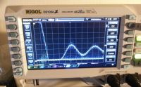
When running from smoothed rectified mains, the pulse skipping circuit works perfectly, and controls power smoothly from zero to full power. It also regulates instantly with load changes, as it should, and runs nicely and quietly. Here's a video showing both fullbridge outputs along with the inverter current (which is just a scaled version of the tank current due to the transformer fed series resonant tank circuit). In the beginning of the video, the tank is unloaded. A graphite crucible is put into the workcoil and removed again to show the effect of loading.
My understanding of control theory falls apart when I try to analyze where the problem is, as I'm having a hard time understanding where my phase margin exists in the circuit. I'm guessing that it's related to the time constant formed by the output impedance of my Variac and the DC bus cap, as the problem goes away when I add a lot of DC bus capacitance. Is there any way to make it more stable without adding said DC bus capacitors, or is there anything else I can do?
Wolfram, Tue Feb 10 2015, 05:50PM
I've implemented pulse skipping for power control now. Both the lower IGBTs in the bridge are turned on for a whole cycle as long as the tank capacitor voltage exceeds the setpoint. Otherwise, the bridge outputs are driven by a 4046 PLL to maintain ZCS.
I've had loads of trouble with stability. I ran the induction heater from unsmoothed rectified mains, and set the pulse skip threshold as a DC value to cut into the peaks of the mains waveform. When the tank voltage exceeds the threshold, it starts pulse skipping but goes into some awful oscillations. The following picture shows the bridge outputs during this oscillation, at 20 microseconds per division. The DC bus voltage oscillates wildly, and actually tries to go below zero. Sorry about the crappy picture, I didn't have a USB stick handy to do a proper oscilloscope screenshot.

When running from smoothed rectified mains, the pulse skipping circuit works perfectly, and controls power smoothly from zero to full power. It also regulates instantly with load changes, as it should, and runs nicely and quietly. Here's a video showing both fullbridge outputs along with the inverter current (which is just a scaled version of the tank current due to the transformer fed series resonant tank circuit). In the beginning of the video, the tank is unloaded. A graphite crucible is put into the workcoil and removed again to show the effect of loading.
My understanding of control theory falls apart when I try to analyze where the problem is, as I'm having a hard time understanding where my phase margin exists in the circuit. I'm guessing that it's related to the time constant formed by the output impedance of my Variac and the DC bus cap, as the problem goes away when I add a lot of DC bus capacitance. Is there any way to make it more stable without adding said DC bus capacitors, or is there anything else I can do?
Re: Adventures in induction heating
Kizmo, Thu Feb 12 2015, 07:36AM
I have seen something similar with my large drsstc driver based induction heater. If you start skipping pulses or interrupting the drive of the LC tank, the energy stored in the tank gets rectified back to your dc bus, have a wild guess how high the dc bus voltage will raise without any capacitance on it? :)
Re: Adventures in induction heating
Uspring, Thu Feb 12 2015, 09:59AM
If you clamp both sides of the full bridge, you probably won't feed much energy back into the mains, since the tank is effectively short circuited. I'm more worried about switching transients. They will lead to spikes on the mains due to mains inductance. Things get particularly bad, if you use rectified mains, since currents going into the mains don't have anywhere to go.
I don't think there's a problem with phase margins, since the circuit seems to run well if pulse skipping is derived from tank current.
Re: Adventures in induction heating
Robert2, Thu Feb 12 2015, 02:45PM
Why do not you try with the measurement of the supply current bridge and on the basis of the value of the thyristor switch- regulate the moment that would be in the system voltage rectifier ?
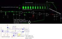
I use such a system to control thyristor bridge with six three-phase mains powered.

Movie, sinusoidal- from AC power, rectangle freely adjustable :)
Robert2, Thu Feb 12 2015, 02:45PM
Why do not you try with the measurement of the supply current bridge and on the basis of the value of the thyristor switch- regulate the moment that would be in the system voltage rectifier ?

I use such a system to control thyristor bridge with six three-phase mains powered.


Movie, sinusoidal- from AC power, rectangle freely adjustable :)
Re: Adventures in induction heating
Wolfram, Thu Mar 05 2015, 03:54PM
Thanks for the suggestions.
I considered the energy transfer between the tank and the bus, but I think this won't be a problem, as the bridge shorts out the load when skipping pulses.
I think mains inductance has something to do with the problem, but I can't really wrap my head around how it ends up oscillating. The problem could be the apparent negative input resistance of the bridge interacting with the bus capacitance and mains inductance. The circuit tries to maintain a constant voltage in the tank circuit, so the input power is constant, and input current sinks with rising input voltage.
In this case, the solution should be simple. Making the pulse skipping threshold track the mains voltage will invert the apparent bridge input impedance back to positive and stabilize it.
Noise doesn't seem to be a big problem so far.
I considered phase angle control with SCRs, but this will ruin the mains power factor.
Re: Adventures in induction heating
Wolfram, Tue Mar 24 2015, 05:45PM
I did end up figuring out the problem with stability, and confirmed it by fixing the problem. It's now stable under all load conditions, and I still haven't managed to break a single IGBT, or any other component for that matter.
With tank voltage control by pulse skipping, the input resistance of the bridge looks negative. As the control circuit tries to maintain a constant voltage across the tank, the power input to the bridge is constant. This means that as the bridge input voltage rises, the current draw goes down, essentially making it look like a negative resistance. This negative resistance can excite resonances in the circuit, which is exactly what happened in my case.
At first, I though the rectifier bridge would eliminate potential resonances between the DC bus capacitors and the mains inductance, like the de-Qing diode in a DC charging Tesla coil, but this is not the case. Mains keeps the diodes forward biased, and allows the DC bus cap to swing with mains inductance. I got the first clue towards this when I tried resonating my DC bus cap with the mains input. The oscillation I saw matched the frequency of the instability. I discussed this with Steve Conner, and he agreed with my interpretation of the problem, and gave me a lot more insight in the process.
To solve this problem is easy, we only need to make the bridge input appear like a positive resistance to dampen any resonance here. Making the tank capacitor voltage track the bridge DC bus voltage will accomplish this nicely, and we need to do this anyways to get reasonable mains power factor. I already tried this earlier, without any success, but I didn't understand the problem properly and made a big mistake. Bridge voltage feedback was taken through a mains transformer for isolation, and the transformer has a low pass characteristic formed by the leakage inductance, stray capacitance and load resistance. This low pass characteristic meant that it only made the bridge input resistance look positive at low frequencies, but not at the resonance frequency of the bus caps and the mains inductance.
Once I understood the problem, I tried again, but without any bandwidth limiting components in the bridge voltage sensing loop. This worked perfectly, and the waveforms are very clean and everything is stable now. I have smooth power control from almost zero up to very high powers, and IGBT losses are as low as they can be. Mains power factor is very good, and the tank current tracks mains current very cleanly without much ripples. I have full control of the switching phase angle through the PLL, and I can tune it for ZVS, ZCS and potentially both. Below is a video of it in operation, with the scope showing the operational waveforms when tuned to ZVS and close to ZCS.
Right now the prototype is limited by heating in the coupling transformer primary. I use two parallel strands of ~1mm dia. teflon insulated silver plated wire, and it gets hot enough to boil water in a few minutes even at moderate power input. The next step is to make a proper PCB for it, and implement inverter overcurrent shutdown to protect against workcoil shorts. Next will be some experiments with using RF powder cores as matching inductors for LCLR. I also have some theory written up that I'll post in this thread when time allows.
Re: Adventures in induction heating
Robert2, Wed Mar 25 2015, 09:20AM
Hi.
I want to do that experiment came to similar conclusions. Actually induction heater controller is very similar to the controller drsstc. In both cases we are to the right so that the phase shift of structure transistors switch to the zeros current ZCS.
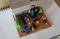
Currently I designed, I hope the final version of the PCB. Is similar to the popular predikter. I decided to use some of OCD (Over Current Detector). I used LM7171 (very fast op-amp), AD790 (very fast comparator) as the original, the first opamp with current transformer is an ideal voltage rectifier two halves of the positive and negative voltage waveform of the transformer. I want OCD system worked as quickly as possible.
Another part of the driver is a PLL 4046, also signals to hit the 74HC109 break after activation OCD zeros excluded the current driver.
I hope that today will guide subsequent trial and plug in ready driver for the heater circuit. At the moment I checked the operation of the controller without a resonant circuit;)

Re: Adventures in induction heating
Linas, Sat Mar 28 2015, 11:26AM
Very nice project and very nice idea.
If i have some time/money i will try to develop STM32F7 based induction heater solution with pulse skipping for power modulation, as well as PLL to compensate for delay, and OCD just like in normal DRSSTC, that will turn off transistor on nearest zero current crossing, or 2x period ( latch-up situation, but at this point, it will not help i think)
And as usual, AMOLED screen with touchscreen for power, voltage, current monitoring as well as other cool stuff.
I have all power electronics, only controller is needed :(
Re: Adventures in induction heating
Robert2, Sun Mar 29 2015, 09:56PM
It's fun. Could using a controller stm try to create a kind of automatic phase shift settings during startup.
Current limit borrowed from predikter-and works well. In the scheme of OCD in preditker is a capacitor setting off time after detecting overcurrent. I used 10uF instead of the original 4.7nF. I lengthened the time 3-5s exemption. Current limit has to work in several situations. Definitely going to work in the event of a short circuit resonant eg. When heated object to tip over. Current limit is also supposed to work when operating winding will be blank.
I have a problem with the current measurement using transformers. The problem is that the resistor power is long enough ... I decided to do this instead of CTs feedback as in the old version that is hooked into a resonant capacitor. Fortunately that the voltage on the capacitor resonant current rises evenly.
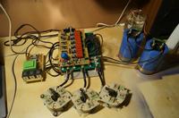
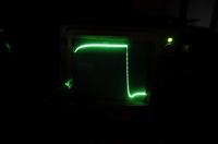
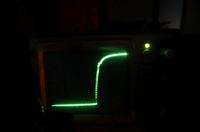
I add pictures on and off the IGBT. The bridge consists of four IGBTs. 1US / div


Re: Adventures in induction heating
Wolfram, Mon Apr 06 2015, 10:09PM
Thanks for the comments guys. I can absolutely recommend the pulse skipping (often called pulse density modulation in papers), as you can control power smoothly without losing ZCS.
Some news on the project. I tried using the induction heater for practical stuff. The biggest limitation now is power dissipation in the coupling transformer primary. When running for a few minutes earlier, it got quite hot, and when trying to run it for longer this week, the insulation on the winding melted and the primary shorted, taking out the IGBTs. The wire I used was teflon insulated stranded 16 AWG silver plated, with two wires in parallel, and when it failed it was carrying around 10 A RMS at 300 kHz.

I suspected the skin effect losses were significant, so I tried replacing it with some heavy litz from an induction stove, 144 strands of 0.25mm for a total cross section of 7 mm^2. This is not ideal for the frequency in question, but should be significantly better than the smaller non-litz wire I used before in terms of skin effect losses. When testing it, there was hardly any improvement. It turns out most of the copper losses were caused by the proximity effect, especially near the secondary where the current density is very high. From a paper I found: "Simply increasing the wire size won't help; unlike skin effect, a larger than optimum wire size can dramatically increase the losses, especially for multiple winding layers. Litz wire is not a panacea and may also increase losses"

To try to minimize this problem, I soldered some copper plates to the secondary. These should hopefully spread out the proximity losses, to avoid overheating the primary near the secondary, and also help with cooling the primary by heat conduction to the water cooled secondary. If needed, the primary can be potted in thermally conductive glue, to help heat conduction to the secondary. I haven't tested it yet, but will update the thread with results

Wolfram, Mon Apr 06 2015, 10:09PM
Thanks for the comments guys. I can absolutely recommend the pulse skipping (often called pulse density modulation in papers), as you can control power smoothly without losing ZCS.
Some news on the project. I tried using the induction heater for practical stuff. The biggest limitation now is power dissipation in the coupling transformer primary. When running for a few minutes earlier, it got quite hot, and when trying to run it for longer this week, the insulation on the winding melted and the primary shorted, taking out the IGBTs. The wire I used was teflon insulated stranded 16 AWG silver plated, with two wires in parallel, and when it failed it was carrying around 10 A RMS at 300 kHz.

I suspected the skin effect losses were significant, so I tried replacing it with some heavy litz from an induction stove, 144 strands of 0.25mm for a total cross section of 7 mm^2. This is not ideal for the frequency in question, but should be significantly better than the smaller non-litz wire I used before in terms of skin effect losses. When testing it, there was hardly any improvement. It turns out most of the copper losses were caused by the proximity effect, especially near the secondary where the current density is very high. From a paper I found: "Simply increasing the wire size won't help; unlike skin effect, a larger than optimum wire size can dramatically increase the losses, especially for multiple winding layers. Litz wire is not a panacea and may also increase losses"


To try to minimize this problem, I soldered some copper plates to the secondary. These should hopefully spread out the proximity losses, to avoid overheating the primary near the secondary, and also help with cooling the primary by heat conduction to the water cooled secondary. If needed, the primary can be potted in thermally conductive glue, to help heat conduction to the secondary. I haven't tested it yet, but will update the thread with results

Re: Adventures in induction heating
Gabriel35, Mon Apr 06 2015, 10:33PM
I'm having problems with the transformer too, It dissipates a lot of heat and this is the worst thing that I saw on the series resonant topology, thinking about goind bat to the Parallel because is much easier to control the power with the air gap on the l-match inductor and much easier to change the number of turns on it...
Re: Adventures in induction heating
Robert2, Tue Apr 07 2015, 06:52AM
I use six wires 1.25mm each twisted tightly and that's enough with 15KW at 550VDC power to the bridge.
What is the frequency of generating power control? I understand that to control the power you generate a square wave signal with a fixed frequency and the duty cycle depends on the power. Is the heater does not work generates weird sounds?
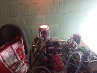
The photo shows a graphite crucible, power 12KW, crucible itself weighs 2kg and warmed up in a few minutes :)
Robert2, Tue Apr 07 2015, 06:52AM
I use six wires 1.25mm each twisted tightly and that's enough with 15KW at 550VDC power to the bridge.
What is the frequency of generating power control? I understand that to control the power you generate a square wave signal with a fixed frequency and the duty cycle depends on the power. Is the heater does not work generates weird sounds?

The photo shows a graphite crucible, power 12KW, crucible itself weighs 2kg and warmed up in a few minutes :)
Re: Adventures in induction heating
Wolfram, Tue Apr 07 2015, 02:24PM
Yeah, the transformer design is one of the most challenging parts. I think a successful design needs to both minimize dissipation and get rid of the heat that is produced in the windings and the core. Understanding the proximity effect is the dominating challenge for me now, I know my new transformer is a lot better but I don't know if it's good enough yet. If it isn't, then thermal glue and foil winding is the next step.
Non-isolated LCLR avoids this problem, and also has some other advantages. I've already written up something about the relative advantages and disadvantages of the different tank circuit arrangements:
A lot has been said about the relative merits of TCSR (transformer coupled series resonant) and LCLR tank circuits. I've seen statements that TCSR has a better power factor or better efficiency than LCLR. This is however not true, and both configurations are pretty similar in practice. I've melted steel with both, and there was no real difference in performance. This is assuming that the matching network is chosen properly, and I assume that people who have had bad experiences with LCLR have had badly chosen component values in the matching network. Theory and simulations also back this up, the phase and amplitude response is very similar between the two configurations near the resonant frequency. Both have a phase angle that crosses through zero at the resonant frequency, so both will have unity power factor at some frequency. Both are also used industrially. There are hower some practical differences between them, which I will try to sum up here.
Edit March 2016: I've done some more reading and simulations, and I have to add some corrections to this. What I wrote about the power factor of LCLR tank circuits only applies at light loading. At heavier loading of the work coil, the inverter current phase angle never crosses zero. This means that the LCLR has worse power factor and no possibility of ZCS with heavier loading.
LCLR advantages:
*Tolerant of work coil shorts, inverter sees a light inductive load
*Can be made without ferrite in the power circuit
*Little added parasitic inductance between the tank capacitor and the work coil, this can be very important with low inductance work coils
*Wiring inductance between inverter and tank circuit will just add to the matching inductor
*Easy to drive a tank from multiple bridges combined through matching inductors
*If the matching inductor is placed near the bridge, the transmission line voltage is sinusoidal, resulting in less radiated noise when the tank is far away
*Mechanically nice tank arrangement
LCLR disadvantages:
*Bad power factor with heavy loading
*No galvanic isolation without an extra transformer
*Requires a matching inductor that can also induction heat surrounding metal
*Current phase angle is not monotonic below resonance, making it hard for a simple PLL to always find resonance
*Matching steals a small part of the tank capacitance. Not usually a big problem
TCSR advantages:
*Unity power factor is possible over a wide range of loading contitions
*Inherent galvanic isolation
*No matching inductor is required
*The phase angle of the inverter current is always monotonic on both sides of resonance, so inverter current feedback can be used
TCSR disadvantages:
*Can be mechanically awkward to make the tank circuit
*Inverter is presented with a capacitive load if workcoil is shorted
*Inductance between the inverter and tank is reflected through the matching transformer, stealing tank VARs.
*Isolation transformer design is difficult at higher frequencies and powers, mostly due to the proximity effect, transformer coupled LCLR has similar challenges.
What frequency are you running at? This is the same cross section i used in the litz wire, and it overheated quickly. At high frequency, the coupling transformer design is very challenging compared to lower frequencies.
I run at 250 - 600 kHz depending on the work coil. Power control is generated from the measured tank voltage, the control circuit will skip whole cycles when the tank circuit voltage is larger than the target.
Wolfram, Tue Apr 07 2015, 02:24PM
Gabriel35 wrote ...
I'm having problems with the transformer too, It dissipates a lot of heat and this is the worst thing that I saw on the series resonant topology, thinking about goind bat to the Parallel because is much easier to control the power with the air gap on the l-match inductor and much easier to change the number of turns on it...
I'm having problems with the transformer too, It dissipates a lot of heat and this is the worst thing that I saw on the series resonant topology, thinking about goind bat to the Parallel because is much easier to control the power with the air gap on the l-match inductor and much easier to change the number of turns on it...
Yeah, the transformer design is one of the most challenging parts. I think a successful design needs to both minimize dissipation and get rid of the heat that is produced in the windings and the core. Understanding the proximity effect is the dominating challenge for me now, I know my new transformer is a lot better but I don't know if it's good enough yet. If it isn't, then thermal glue and foil winding is the next step.
Non-isolated LCLR avoids this problem, and also has some other advantages. I've already written up something about the relative advantages and disadvantages of the different tank circuit arrangements:
A lot has been said about the relative merits of TCSR (transformer coupled series resonant) and LCLR tank circuits. I've seen statements that TCSR has a better power factor or better efficiency than LCLR. This is however not true, and both configurations are pretty similar in practice. I've melted steel with both, and there was no real difference in performance. This is assuming that the matching network is chosen properly, and I assume that people who have had bad experiences with LCLR have had badly chosen component values in the matching network. Theory and simulations also back this up, the phase and amplitude response is very similar between the two configurations near the resonant frequency. Both have a phase angle that crosses through zero at the resonant frequency, so both will have unity power factor at some frequency. Both are also used industrially. There are hower some practical differences between them, which I will try to sum up here.
Edit March 2016: I've done some more reading and simulations, and I have to add some corrections to this. What I wrote about the power factor of LCLR tank circuits only applies at light loading. At heavier loading of the work coil, the inverter current phase angle never crosses zero. This means that the LCLR has worse power factor and no possibility of ZCS with heavier loading.
LCLR advantages:
*Tolerant of work coil shorts, inverter sees a light inductive load
*Can be made without ferrite in the power circuit
*Little added parasitic inductance between the tank capacitor and the work coil, this can be very important with low inductance work coils
*Wiring inductance between inverter and tank circuit will just add to the matching inductor
*Easy to drive a tank from multiple bridges combined through matching inductors
*If the matching inductor is placed near the bridge, the transmission line voltage is sinusoidal, resulting in less radiated noise when the tank is far away
*Mechanically nice tank arrangement
LCLR disadvantages:
*Bad power factor with heavy loading
*No galvanic isolation without an extra transformer
*Requires a matching inductor that can also induction heat surrounding metal
*Current phase angle is not monotonic below resonance, making it hard for a simple PLL to always find resonance
*Matching steals a small part of the tank capacitance. Not usually a big problem
TCSR advantages:
*Unity power factor is possible over a wide range of loading contitions
*Inherent galvanic isolation
*No matching inductor is required
*The phase angle of the inverter current is always monotonic on both sides of resonance, so inverter current feedback can be used
TCSR disadvantages:
*Can be mechanically awkward to make the tank circuit
*Inverter is presented with a capacitive load if workcoil is shorted
*Inductance between the inverter and tank is reflected through the matching transformer, stealing tank VARs.
*Isolation transformer design is difficult at higher frequencies and powers, mostly due to the proximity effect, transformer coupled LCLR has similar challenges.
I use six wires 1.25mm each twisted tightly and that's enough with 15KW at 550VDC power to the bridge.
What frequency are you running at? This is the same cross section i used in the litz wire, and it overheated quickly. At high frequency, the coupling transformer design is very challenging compared to lower frequencies.
What is the frequency of generating power control? I understand that to control the power you generate a square wave signal with a fixed frequency and the duty cycle depends on the power. Is the heater does not work generates weird sounds?
I run at 250 - 600 kHz depending on the work coil. Power control is generated from the measured tank voltage, the control circuit will skip whole cycles when the tank circuit voltage is larger than the target.
Re: Adventures in induction heating
Gabriel35, Tue Apr 07 2015, 02:59PM
The cycle skipping seems to be a great ideia. Do you have plans on posting some schematics of it soon?
What are the switches you are currently using?
In my IH, I'm using the TCSR now for testing and I think that the material of my cheap toroids is bad or not made for that purpose because the windings do not heat, the only thing that heats up are the toroidal cores...
Re: Adventures in induction heating
Wolfram, Tue Apr 07 2015, 04:23PM
I've attached the current schematic. The bus voltage sensing is not isolated from mains, but it will be in the final version. The current solution is just something I threw together to see if it would stabilize the circuit, see earlier posts in the thread for more info on this.

I'm currently using Fairchild FGH40T65SPD, they are very cheap and low loss. I've only killed IGBTs once, and that was when the primary of the coupling transformer melted and shorted. I've attached an image of the broken IGBTs. As you can see, the dies are very small, but they can still handle switching significant power on account of their very low losses. I prefer to have low loss IGBTs instead of older devices with larger dies that are more robust but more lossy.

What core are you using for the coupling transformer and what frequency are you operating at?
Wolfram, Tue Apr 07 2015, 04:23PM
Gabriel35 wrote ...
The cycle skipping seems to be a great ideia. Do you have plans on posting some schematics of it soon?
What are the switches you are currently using?
In my IH, I'm using the TCSR now for testing and I think that the material of my cheap toroids is bad or not made for that purpose because the windings do not heat, the only thing that heats up are the toroidal cores...
I've attached the current schematic. The bus voltage sensing is not isolated from mains, but it will be in the final version. The current solution is just something I threw together to see if it would stabilize the circuit, see earlier posts in the thread for more info on this.

I'm currently using Fairchild FGH40T65SPD, they are very cheap and low loss. I've only killed IGBTs once, and that was when the primary of the coupling transformer melted and shorted. I've attached an image of the broken IGBTs. As you can see, the dies are very small, but they can still handle switching significant power on account of their very low losses. I prefer to have low loss IGBTs instead of older devices with larger dies that are more robust but more lossy.

What core are you using for the coupling transformer and what frequency are you operating at?
Re: Adventures in induction heating
Robert2, Wed Apr 08 2015, 07:42AM
Hi There
My transformer is 9 pieces of toroidal cores TX58 3E25
The resonant frequency is 30 kHz
MMC resultant capacity is about 5uF
Robert2, Wed Apr 08 2015, 07:42AM
Hi There
My transformer is 9 pieces of toroidal cores TX58 3E25
The resonant frequency is 30 kHz
MMC resultant capacity is about 5uF


Re: Adventures in induction heating
Gabriel35, Wed Apr 08 2015, 02:52PM
Hello Wolfram!
My Tank caps are 48x 110nF - 630v MKPs
My workcoil is about 0.8uH (so 77,8Khz)
And I have no idea of what's the material of the cores, since I extracted them from a SEW Eurodrive 3-phase filter used probably on industrial inverters.
The other options that I have In hands are those Yellow and white cores from ATX supplys, that are bad I think...
But... I have some nice and big ferrite E-cores, so for me is much easier building an LCLR IH...
Re: Adventures in induction heating
Claude, Sun Apr 19 2015, 08:03AM
Hi Wolfram, I like your method of power control by pulse skipping and have read your link to the pulse skipping article but I am having trouble understanding it.
I have built a series resonant induction heater and would like to implement this form of power control. I have been bench testing a jk flip flop but I can see that it skips only every second cycle once the comparator reaches its threshold. Is this correct?
I am using a halfbridge. Is it possible to implement pulse skipping with a halfbridge as I noticed that you are using a fullbridge.
Thankyou.
Claude.
Re: Adventures in induction heating
Wolfram, Mon Apr 20 2015, 03:28PM
Hey Claude. The method isn't new, but I've only seen a few people here use it, most notably Steve Conner in his PLL DRSSTC driver. In the litterature it is often called Pulse Density Modulation (PDM), so if you want to find more info this is a good name to search for.
The method is pretty simple. In my implementation, I use the sensed voltage from the tank cap to control the skipping. Whenever the capacitor voltage is higher than the reference, the bridge outputs are disabled. The number of cycles that will be skipped depends on the reference and how much load is placed in the heater. You need to make sure that it skips an even number of cycles so that you have the same number of positive and negative cycles. If you clock the JK flip flop from the same signal that controls the bridge, it will always skip an even number of cycles.
You also need to make sure that the phasing between the sense signal (tank voltage or current) is matched to when you need the signal. The tank voltage is shifted 90 degrees in relation to the bridge output voltage. The JK flip flop samples on the rising edge of one of the bridge outputs, so exactly when the cap voltage peaks. This means you can connect your comparator directly to the JK flip flop. I used this method originally, but there is some risk of metastability if the flip flop is clocked exactly when the comparator output changes state, so I went to a different method.
If you use tank or inverter current for feedback, the bridge output switching matches with the inverter/tank current zero crossing, so you need a second flip flop to hold the comparator state until the "Enable" flip flop can sample it. This method can also be used with tank voltage sensing, and it will solve the metastability problem. This is what I'm doing now, and you can see it in my latest schematic.
If you have little smoothing on the DC bus, it is important that you get the comparator reference voltage from the DC bus voltage. This will ensure that the circuit will be stable, and it will also ensure good power factor. If you have large electrolytics across the DC bus, it is not that critical, but still a very good idea.
For skipping pulses, I turn on both bottom switches to short out the tank circuit. This traps energy in the tank. This is not possible to do with a half-bridge, but you can open both switches to recycle the energy back to the DC bus, and it will still work fine. This is what Steve Conner does in his PLL DRSSTC driver.
What is your circuit like now? Do you have a schematic?
Right, these are no good here. The yellow/white ones are iron powder. These are very lossy for HF transformers, and the permeability is low so magnetizing current will also be high. Ferrite is the only good alternative at these frequencies. I looked a bit into using RF type iron powder cores (Micrometals type 2) for the matching inductor in an LCLR heater, but they are simply too lossy at reasonable flux densities. Ferrite and air core are the only options that seem realistic.
As a final note, I want to try a transformer coupled LCLR where the matching inductor is designed as leakage inductance in the isolating transformer, just like the current limiting shunts in neon sign transformers and microwave oven transformers.
Wolfram, Mon Apr 20 2015, 03:28PM
Claude wrote ...
Hi Wolfram, I like your method of power control by pulse skipping and have read your link to the pulse skipping article but I am having trouble understanding it.
I have built a series resonant induction heater and would like to implement this form of power control. I have been bench testing a jk flip flop but I can see that it skips only every second cycle once the comparator reaches its threshold. Is this correct?
I am using a halfbridge. Is it possible to implement pulse skipping with a halfbridge as I noticed that you are using a fullbridge.
Thankyou.
Claude.
Hey Claude. The method isn't new, but I've only seen a few people here use it, most notably Steve Conner in his PLL DRSSTC driver. In the litterature it is often called Pulse Density Modulation (PDM), so if you want to find more info this is a good name to search for.
The method is pretty simple. In my implementation, I use the sensed voltage from the tank cap to control the skipping. Whenever the capacitor voltage is higher than the reference, the bridge outputs are disabled. The number of cycles that will be skipped depends on the reference and how much load is placed in the heater. You need to make sure that it skips an even number of cycles so that you have the same number of positive and negative cycles. If you clock the JK flip flop from the same signal that controls the bridge, it will always skip an even number of cycles.
You also need to make sure that the phasing between the sense signal (tank voltage or current) is matched to when you need the signal. The tank voltage is shifted 90 degrees in relation to the bridge output voltage. The JK flip flop samples on the rising edge of one of the bridge outputs, so exactly when the cap voltage peaks. This means you can connect your comparator directly to the JK flip flop. I used this method originally, but there is some risk of metastability if the flip flop is clocked exactly when the comparator output changes state, so I went to a different method.
If you use tank or inverter current for feedback, the bridge output switching matches with the inverter/tank current zero crossing, so you need a second flip flop to hold the comparator state until the "Enable" flip flop can sample it. This method can also be used with tank voltage sensing, and it will solve the metastability problem. This is what I'm doing now, and you can see it in my latest schematic.
If you have little smoothing on the DC bus, it is important that you get the comparator reference voltage from the DC bus voltage. This will ensure that the circuit will be stable, and it will also ensure good power factor. If you have large electrolytics across the DC bus, it is not that critical, but still a very good idea.
For skipping pulses, I turn on both bottom switches to short out the tank circuit. This traps energy in the tank. This is not possible to do with a half-bridge, but you can open both switches to recycle the energy back to the DC bus, and it will still work fine. This is what Steve Conner does in his PLL DRSSTC driver.
What is your circuit like now? Do you have a schematic?
The other options that I have In hands are those Yellow and white cores from ATX supplys, that are bad I think...
Right, these are no good here. The yellow/white ones are iron powder. These are very lossy for HF transformers, and the permeability is low so magnetizing current will also be high. Ferrite is the only good alternative at these frequencies. I looked a bit into using RF type iron powder cores (Micrometals type 2) for the matching inductor in an LCLR heater, but they are simply too lossy at reasonable flux densities. Ferrite and air core are the only options that seem realistic.
As a final note, I want to try a transformer coupled LCLR where the matching inductor is designed as leakage inductance in the isolating transformer, just like the current limiting shunts in neon sign transformers and microwave oven transformers.
Re: Adventures in induction heating
Claude, Tue Apr 21 2015, 09:59AM
Hi Wolfram, thankyou for the excellent explanation of your method of pulse skipping. I am able to understand it much better.
My circuit is similar to Uzzors pll series induction heater(I am unable to post a link)except that I don't have the tank overvoltage protection and I use the UCC driver ic's with a gate drive transformer. I like those Silabs drivers that you have. It works well at low power but I have not tried it on a high power level, that's why I would like to try pulse skipping. I will keep you updated.
Claude.
Re: Adventures in induction heating
Claude, Thu Apr 30 2015, 12:05PM
Hi Wolfram,I have been working on the pulse skipping circuit but having some problems. It is similar to yours except that the reference for the comparator is taken from the +15v supply. I am using cmos logic and I have 1500uf of bus capacitance. Operating frequency is 80Khz.
The pulse skipping works reasonably well until it tries to skip too many pulses and then the comparator output seems to latch, outputting pulses the same frequency as resonance therefore acting as if there was no pulse skipping or current limit. This is noticeable if the workpiece is removed slowly from the coil. It will skip pulses up to when the piece is about halfway out and if it is removed any further it will latch on fully. I have tried two different comparators with the same result, LM319 and LM393. What comparator are you using?
Do you use the Set & Reset from the same flip flop as the clock input or is it a seperate flip flop? I have tried both and the one from the same flip flop works best.
I noticed in your last video that you showed a pulse skip trigger. Is this the comparator output?
I am thinking that the problem might be with the reference for the comparator, but I remember you saying that if there is a lot of bus capacitance is is not critical.
Claude.
Re: Adventures in induction heating
Wolfram, Thu Apr 30 2015, 02:00PM
Hey Claude.
So if I understand right, when you place a load in the coil and remove it, at some point it will latch on and current draw will go way up? Some comparators can have unexpected behavior when either input goes beyond the acceptable range, especially with these old comparators. Are you running the comparator from +15V and GND? Can you draw a schematic of your current implementation with the flipflops and provide some oscilloscpe pictures? There are many ways to do the relative phasing between the tank circuit voltage and the logic, and this can lead to some confusing problems.
I'm using some obsolete comparator I found, I'm out travelling for the weekend so I can't check the part number, but I think it was the CMP-01. It's not ideal but it was the best I had at hand. I've ordered PCBs for the next revision of the prototype, and for this I will use the MCP6562 which is superior in every respect and very cheap.
Currently my flipflops are connected like in the last schematic I posted, I can doublecheck when I get home on Sunday. It took some time to figure out the right phasing between the PLL and the pulse skipping.
The pulse skip trigger (blue trace) in my video is the comparator output yeah.
As you mentioned, I had some instability when using a DC reference for the comparator, but not when I had an electrolytic (470 µF) across the DC bus. This is only a problem when running with little bus capacitance. If you run into this problem, it will look like oscillations on the DC bus and potentially some awful noises.
Re: Adventures in induction heating
Claude, Sat May 02 2015, 12:29PM
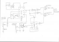
Hi Wolfram, I have posted my schematic and some scope shots.
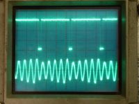
First scope shot, upper trace is disable pulse from flipflop. Disable pulse must go low to disable driver chips. Lower trace is inverter current.
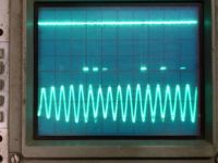
Second scope shot, more pulses skipped. Upper trace disable pulse. Lower trace is inverter current.
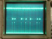
Third scope shot, upper trace is disable pulse. Lower trace is output from comparator.
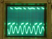
Fourth scope shot, upper trace is inverter output. Lower trace is inverter current.
Sorry for the quality of the pictures.
I have noticed that when I increase power with the variac it starts skipping pulses and the inverter positive output stops rising but inverter negative voltage swing keeps increasing until it no longer skips pulses and inverter current rises out of control.
Claude.


Re: Adventures in induction heating
Wolfram, Mon May 04 2015, 12:31PM
Thanks for the schematic and scope shots, that makes it clearer.
I think there are a couple of problems with the circuit. The reset signal for the 4027 comes from an inverter from the clock to the 4027. The 4027 samples on the rising edge, and when this happens the reset will still be high due to the propagation delay of the inverter. Since the reset is high when the clock rises, the clock doesn't do anything and you essentially have an RS-flip-flop. The pulse-skipping will not be synchronized to the bridge switching, but due to the 90 degree shift between the bridge voltage (fundamental) and the capacitor voltage it will be close to the current zero crossing. It would not be so bad if the phase shift was always known to be exactly 90 degrees, but you don't know that because of your loop filter. The PLL loop filter is not ideal, the loop time constant and loop gain are set by the same control, and the phase shift will depend on where in the lock range the PLL is running. These things together could lead to some interesting interactions between the PLL and pulse skip circuit. Your circuit could easily be changed to be identical to my first one, which should be immune to these problems.
I'm not sure if this is the reason for your trouble. It could also be something else. When you run the pulse skip setpoint from a fixed DC voltage, the circuit will always try to maintain a given tank voltage. This also means that the input power is a fixed value, and if the input voltage decreases then the current needs to increase to maintain the power. If the supply impedance is relatively high, it could happen that as the voltage dips, the current needed to maintain the power makes the voltage sink even more, which leads to increased current again, essentially forming a positive feedback loop. This is a problem with any regulated supply and power converter. If this happens, you will see the input current skyrocket, the input voltage fall, and the tank voltage (and current) stay constant.
Re: Adventures in induction heating
Claude, Tue May 05 2015, 05:13AM
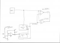
hello Wolfram, I think I have solved part of my problem but created another. Looking at my first schematic, when the pulse from the pll goes from high to low it is inverted and puts the reset high.This resets the flipflop causing only half the cycle to be skipped. This is why the negative portion of the bridge voltage kept increasing.
I have now simplified my circuit by replacing one of the drivers with a non-inverting one. This allows me to remove the inverter logic and use the same disable pulse to reset the flipflop. The disable pulse must go low to disable the driver ic's. This now allows complete cycles to be skipped. I have tested it at low power and it works well. I can even remove the workpiece and more cycles will skip and inverter current will stay at the set level. The problem which I have now is that sometimes when I apply power to the control circuit the Q output from the A flipflop will not go high to enable the driver ic's. Not sure if it is a timing problem as it happens randomly. I would to try to take the reference for the comparator from the buss voltage as you did to see if it makes a difference but I am a bit concerned about connecting the negative of the buss to the negative of the low voltage 15V supply.
I read your explanation of the phase locking network. I don't seem to have noticed any problems with mine. It keeps a tight lock on the phase relationship even when I place different sizes of metals in the coil.
I would like to ask you, should the output of the comparator be in phase with the top of the sinewave of the capacitor voltage. I have noticed that the comparator output slightly lags the capacitor voltage.
Claude.

Re: Adventures in induction heating
Wolfram, Mon May 11 2015, 05:40PM
That looks better, but there's still something which bothers me a bit. You've connected together J and K. Q will toggle when both are high, and remain the same when both are low. This means that after it skips a pulse, it could potentially stay disabled, and if two subsequent pulses need to be skipped, it would be re-enabled on the next cycle. To get the proper function, you should invert the K signal going into the JK flip-flop (in effect making it a D flip flop).
For your second question, the output of the comparator should be high whenever the tank capacitor voltage (divided down) is higher than the setpoint voltage for the comparator, plus any delay from the comparator itself.
There have been some updates on the project. The prototype was getting a bit complex, so I designed and ordered a board for it. With the newest changes, it's a bit closer to Steve Conner's DRSSTC driver. Now I take PLL feedback from the tank current intstead of the voltage. As the current should be in phase with the bridge voltage, I needed to cancel out the 90 degree shift from the XOR phase comparator. I used Steve's trick here, where I make the PLL run at 2x Fres by placing a divider in the feedback loop, and use a divider with an inverted clock to get back to Fres with an added 90 degree phase shift. This adds up to a 180 degree phase shift, which can easily be cancelled by inverting the signal.
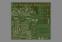
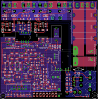
The boards I designed 2 layers, and they include the latest feedback, bus voltage sensing and additional protection circuits. If everything works as expected, I already have a 4 layer design with more improvements ready to go to production. The 4-layer design should provide much better current handling for the bridge, and better signal integrity as well. The board is designed to have all the essential functions on-board, including the power supply. The only thing needed to make them run is to connect a potentiometer for power control and a few buttons and LEDs for start/stop and status. The control port also includes other signals like tank and mains current sensing, mains voltage sensing, VCO frequency and others, so that a more elaborate control panel can be made at a later point. All protection functions are inherent, so it will run safely with the minimal control interface.
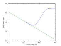
As for the coupling transformer, I did some reading and simulations on the proximity effect, and it turns out that using conductors thicker than a fraction of the skin depth will radically increase the effective AC resistance, by as much as a factor of 100. Skin effect tells us that there's little benefit from any conductor over a given size (aside from increased surface area and thermal mass), but I didn't expect a too large conductor to make things that much worse. I did some simulations in Matlab, the following plot shows the effective AC resistance of a 20 layer foil primary as a function of the foil thickness. The green line is the DC resistance and the blue line is the AC ressitance at 300kHz. Notice how it goes up drastically beyond the ideal thickness. Luckily, the ideal thickness is the same as the thickness of regular copper tape.
Wolfram, Mon May 11 2015, 05:40PM
That looks better, but there's still something which bothers me a bit. You've connected together J and K. Q will toggle when both are high, and remain the same when both are low. This means that after it skips a pulse, it could potentially stay disabled, and if two subsequent pulses need to be skipped, it would be re-enabled on the next cycle. To get the proper function, you should invert the K signal going into the JK flip-flop (in effect making it a D flip flop).
For your second question, the output of the comparator should be high whenever the tank capacitor voltage (divided down) is higher than the setpoint voltage for the comparator, plus any delay from the comparator itself.
There have been some updates on the project. The prototype was getting a bit complex, so I designed and ordered a board for it. With the newest changes, it's a bit closer to Steve Conner's DRSSTC driver. Now I take PLL feedback from the tank current intstead of the voltage. As the current should be in phase with the bridge voltage, I needed to cancel out the 90 degree shift from the XOR phase comparator. I used Steve's trick here, where I make the PLL run at 2x Fres by placing a divider in the feedback loop, and use a divider with an inverted clock to get back to Fres with an added 90 degree phase shift. This adds up to a 180 degree phase shift, which can easily be cancelled by inverting the signal.

The boards I designed 2 layers, and they include the latest feedback, bus voltage sensing and additional protection circuits. If everything works as expected, I already have a 4 layer design with more improvements ready to go to production. The 4-layer design should provide much better current handling for the bridge, and better signal integrity as well. The board is designed to have all the essential functions on-board, including the power supply. The only thing needed to make them run is to connect a potentiometer for power control and a few buttons and LEDs for start/stop and status. The control port also includes other signals like tank and mains current sensing, mains voltage sensing, VCO frequency and others, so that a more elaborate control panel can be made at a later point. All protection functions are inherent, so it will run safely with the minimal control interface.

As for the coupling transformer, I did some reading and simulations on the proximity effect, and it turns out that using conductors thicker than a fraction of the skin depth will radically increase the effective AC resistance, by as much as a factor of 100. Skin effect tells us that there's little benefit from any conductor over a given size (aside from increased surface area and thermal mass), but I didn't expect a too large conductor to make things that much worse. I did some simulations in Matlab, the following plot shows the effective AC resistance of a 20 layer foil primary as a function of the foil thickness. The green line is the DC resistance and the blue line is the AC ressitance at 300kHz. Notice how it goes up drastically beyond the ideal thickness. Luckily, the ideal thickness is the same as the thickness of regular copper tape.

Re: Adventures in induction heating
mister_rf, Tue May 12 2015, 07:18PM
Very professional job done here. I like to learn from your experience. I already adapted my own project to include the pulse skipping concept.
mister_rf, Tue May 12 2015, 07:18PM
Very professional job done here. I like to learn from your experience. I already adapted my own project to include the pulse skipping concept.

Re: Adventures in induction heating
Wolfram, Wed May 13 2015, 02:00PM
Thanks. I'm sure you will like it, it can be a bit tricky to get all the phasing and timing right, and bus feedback is essential when running from unsmoothed mains, but the high efficiency and clean switching is definitely worth it.
The first revision of the prototype boards arrived yesterday, and I hope to put one together within the next few days, if time allows. 10 boards at a cost of 25 dollars including shipping is not bad at all, and makes it easy to do prototypes on PCB.
I'm doing some changes to the 4 layer board as well, so that the IGBTs and rectifier can be mounted on the underside of the board. This allows for easier mechanical mounting.
Wolfram, Wed May 13 2015, 02:00PM
mister_rf wrote ...
Very professional job done here. I like to learn from your experience. I already adapted my own project to include the pulse skipping concept.
Very professional job done here. I like to learn from your experience. I already adapted my own project to include the pulse skipping concept.

Thanks. I'm sure you will like it, it can be a bit tricky to get all the phasing and timing right, and bus feedback is essential when running from unsmoothed mains, but the high efficiency and clean switching is definitely worth it.
The first revision of the prototype boards arrived yesterday, and I hope to put one together within the next few days, if time allows. 10 boards at a cost of 25 dollars including shipping is not bad at all, and makes it easy to do prototypes on PCB.
I'm doing some changes to the 4 layer board as well, so that the IGBTs and rectifier can be mounted on the underside of the board. This allows for easier mechanical mounting.
Re: Adventures in induction heating
mister_rf, Thu May 14 2015, 04:32PM
I had been snooping at your project, and there’s something I’m not sure about.
Are you using the 74109 series on IC2 also? There are some “strange†connections regarding that circuit.
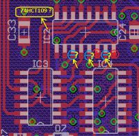
mister_rf, Thu May 14 2015, 04:32PM
I had been snooping at your project, and there’s something I’m not sure about.

Are you using the 74109 series on IC2 also? There are some “strange†connections regarding that circuit.

Re: Adventures in induction heating
Wolfram, Thu May 14 2015, 05:14PM
You're correct that it's a 74109, it's the loop divider for the PLL. Running the PLL at 2x Fres makes it easy to digitally phase shift the feedback signal by 90 degrees, to compensate for the 90 degree phase shift of the XOR phase detector, so that current feedback can be used. The circuit is taken from Conner's DRSSTC controller.
Earlier I used tank capacitor feedback, which was naturally 90 degrees shifted from the inverter current, but I already needed a current transformer on the bridge output for inverter protection, and adding a single 74HC109 allowed me to use this for feedback as well. This has the added benefit of galvanic isolation, so that I can use the driver with non-isolated LCLR as well. Note that for LCLR, the current feedback can not be taken from the inverter output (the phase angle is not monotonic below resonance), so the CT needs to be fed from a sample of the tank current, which can be done easily by sensing the current through a small capacitor in parallel with the tank. This will sacrifice inverter overcurrent protection, but LCLR is inherently immune to work coil shorts so that's not a big problem.
I've attached the schematic, and feel free to IM me anybody who wants the raw eagle files. Keep in mind that this is a revision that's not yet tested so there might be errors. I haven't cleaned up the schematic so it's a bit messy and some component values are wrong, but it is more useful than reading the circuit from the board.
Edit: the file attachment function isn't working right now so I uploaded the schematic to my dropbox:

Re: Adventures in induction heating
mister_rf, Thu May 14 2015, 06:24PM
let's see if my initial guess about your schematic was close to the original...
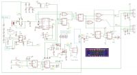
Later edit
Well, maybe I have missed something, but in my opinion I have spotted an error there.
The asynchronous reset-direct input Rd and the asynchronous set-direct input Sd are both active low inputs, and the L&L combination must be avoided. Am I right?
mister_rf, Thu May 14 2015, 06:24PM
let's see if my initial guess about your schematic was close to the original...


Later edit
Well, maybe I have missed something, but in my opinion I have spotted an error there.
The asynchronous reset-direct input Rd and the asynchronous set-direct input Sd are both active low inputs, and the L&L combination must be avoided. Am I right?

Re: Adventures in induction heating
Wolfram, Thu May 14 2015, 07:53PM
Wow, that's very close, impressive work. I could have given you the schematic if you had asked, but I guess you are like me and enjoy some nice reverse engineering work :)
That's a nice catch, you're completely correct. I've apparently done this mistake several places, where I've grounded the asynchronous SR inputs on the flip flops wher they are not used. I'm too used to flipflops with non-inverting SR inputs so I connected them to ground without even thinking about it. You saved me significant troubleshooting time and confusion there, thanks a lot. I will fix it right away.
Edit: I've fixed it now, and the updated schematic is here: . Please tell me if you notice anything else that seems wrong. I've quickly gone over all the logic polarities and I didn't see anything else obviously wrong.
Wolfram, Thu May 14 2015, 07:53PM
mister_rf wrote ...
let's see if my initial guess about your schematic was close to the original...

Later edit
Well, maybe I have missed something, but in my opinion I have spotted an error there.
The asynchronous reset-direct input Rd and the asynchronous set-direct input Sd are both active low inputs, and the L&L combination must be avoided. Am I right?
let's see if my initial guess about your schematic was close to the original...


Later edit
Well, maybe I have missed something, but in my opinion I have spotted an error there.
The asynchronous reset-direct input Rd and the asynchronous set-direct input Sd are both active low inputs, and the L&L combination must be avoided. Am I right?

Wow, that's very close, impressive work. I could have given you the schematic if you had asked, but I guess you are like me and enjoy some nice reverse engineering work :)
That's a nice catch, you're completely correct. I've apparently done this mistake several places, where I've grounded the asynchronous SR inputs on the flip flops wher they are not used. I'm too used to flipflops with non-inverting SR inputs so I connected them to ground without even thinking about it. You saved me significant troubleshooting time and confusion there, thanks a lot. I will fix it right away.
Edit: I've fixed it now, and the updated schematic is here:
 . Please tell me if you notice anything else that seems wrong. I've quickly gone over all the logic polarities and I didn't see anything else obviously wrong.
Re: Adventures in induction heating
Wolfram, Tue Jun 16 2015, 08:07PM
It's been a while since I updated this thread. The project hasn't been inactive though, it's just hard to find time to sit down and document it these days.
A lot has happened in the meantime. I received the prototype boards a few weeks after ordering them, and managed to put one together. Some bodges with magnet wire were needed, as the boards were submitted to production before mister_rf found my flip-flop wiring bug. Everything works correctly, including the pulse density modulation and overcurrent detection, but there are still some things I want to improve. There are mainly two issues which i'll describe here.
The first issue is that the PLL easily loses lock. Especially at low bus voltage, low pulse density settings and when the PLL is set to switch early. This was never a problem in my first prototype that used capacitor voltage feedback, so it must be fixable. I did some modifications that improved the situation, but it still loses lock under some conditions so I'm working through the circuit step by step to make it more stable. The main modification that helped was to limit the upper and lower frequency of the PLL. The lower frequency can easily be changed with the resistor connected to pin 12 of the 4046, and the upper frequency can be limited by a voltage divider between the loop filter and the VCO input. Limiting the minimum power setting also helps. I'm slowly working through the circuit, using the totally stable prototype 1 as a comparison.
The second problem is more subtle and more fundamental. It's not really a big problem, so I didn't notice it until now, but I still want to fix it. The symptom is that the switching phase angle changes with the pulse density setting. The change is not huge, and the target phase can be set so that soft switching is maintained down to some reasonably low pulse density setting. The reason for the problem was a bit more mysterious, but again Steve Conner gave me some ideas. The fundamental problem is that the PLL loop dynamics change when pulses are skipped. During this idle time, the PLL is sensing tank current but not controlling it. For my circuit to work properly, the PLL loop needs to be stable both when the loop is open and closed. I've only designed the loop filter for stability when running closed loop. Indeed, the integrator loop filter will be unstable when running open loop, and the frequency drifts during the idle time. Now I need to figure out a loop filter to make it stable in both conditions. Most likely, this will only need an extra resistor and maybe a cap, but I haven't dug that deep into the theory yet. Hopefully, fixing this problem will also help with the first problem.
The values that need tweaking in my schematic are the following: The low pass filter for the bus voltage sensing needs to suppress switching noise but still be fast enough to stabilise the bus voltage. I ended up using 10k/100p , but even more capacitance could help when using lower switching frequencies. The dead-time should be set for a few hundred nanoseconds as a starting point. Target phase needs to be tweaked until it locks and then for ZVS and/or ZCS.
Re: Adventures in induction heating
Wolfram, Mon Jul 13 2015, 04:17PM
I've now figured out both problems from the previous post.
Part of the lock problem was caused by strange behavior of the 74HC4046 VCO outside of the recommended input voltage range. The TI datasheet recommends staying between 1 and 4 V for VCOin. My circuit does not have a restriction on the VCO input voltage, so it can potentially be between 0 and 5 V. The chip I used for the first prototype behaved nicely from 0 to 5 V, but for the second prototype I used a 74HC4046 from TI, which does some very strange things. Below 0.8 V in, the frequency steps abruptly to half of the value, and any further lowering of the control voltage has no effect at all. Increasing the control voltage above 4 V leads to an exponential rise in the output frequency until it hits 10 + MHz at 5V (with a 1 nF timing cap). Needless to say, this does some strange things to the loop dynamics, and the thing was hard to get stable, especially when the resonance frequency ends up in the middle of the step around 0.8 V. I added a resistor network, with 12k to VCC, 12k to GND and 6k8 to the loop filter output, all connected to VCOin. This made it behave a lot better.
I was still not entirely happy with the PLL current feedback. It's hard to get nice feedback with low phase shift when far from the resonant frequency. I experimented a bit more with capacitor voltage feedback, and it's a lot easier to get working well. Since I want to use capacitor voltage sensing for capacitor protection, there's no disadvantage to changing back to capacitor voltage feedback. After playing a bit with LTSpice, I managed to make a nice network for measuring average cap voltage and phase, without introducing unreasonable phase shifts or zero crossing asymmetry over a wide range of voltages and frequencies.
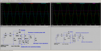
The second problem turned out to not be a problem at all. The switching phase angle appeared to change when the pulse density was adjusted, but this was not what was actually happening. As I was adjusting the pulse density, the primary current changed, and since this current is what commutates the midpoint voltage, it appeared the same way as adjusting the switching phase angle. Now that I understand it, I don't worry about it. Even if adjusted for perfect ZVS at maximum power only, the lower conduction losses will compensate for the increased switching losses at lower pulse densities. It's also possible to inject the sensed primary current into the phase setpoint to compensate, but I don't think it's worth the effort for a marginal increase in efficiency.
Feeling relatively comfortable about the design, I finalized my four layer board and ordered boards. There have been significant changes since the last screenshots I posted. The FR4 thickness between layers 1/2 and 3/4 is significantly thinner than between 2/3, so I moved around some layers to minimize bridge midpoint capacitance. I've moved the IGBTs and changed how they will be mounted. Some hold-down brackets will be glued to the bottom of the PCB, and these will clamp the IGBTs to the heatsink with even pressure over the die. Whether this is practical remains to be seen.
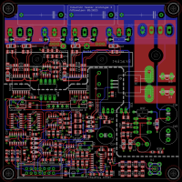
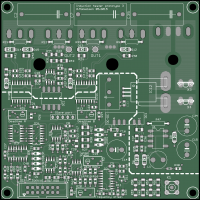
To modify my previous design to work like the latest version only needs some minor mods. I can try to draw up a schematic of what to do in the near future.
Wolfram, Mon Jul 13 2015, 04:17PM
I've now figured out both problems from the previous post.
Part of the lock problem was caused by strange behavior of the 74HC4046 VCO outside of the recommended input voltage range. The TI datasheet recommends staying between 1 and 4 V for VCOin. My circuit does not have a restriction on the VCO input voltage, so it can potentially be between 0 and 5 V. The chip I used for the first prototype behaved nicely from 0 to 5 V, but for the second prototype I used a 74HC4046 from TI, which does some very strange things. Below 0.8 V in, the frequency steps abruptly to half of the value, and any further lowering of the control voltage has no effect at all. Increasing the control voltage above 4 V leads to an exponential rise in the output frequency until it hits 10 + MHz at 5V (with a 1 nF timing cap). Needless to say, this does some strange things to the loop dynamics, and the thing was hard to get stable, especially when the resonance frequency ends up in the middle of the step around 0.8 V. I added a resistor network, with 12k to VCC, 12k to GND and 6k8 to the loop filter output, all connected to VCOin. This made it behave a lot better.
I was still not entirely happy with the PLL current feedback. It's hard to get nice feedback with low phase shift when far from the resonant frequency. I experimented a bit more with capacitor voltage feedback, and it's a lot easier to get working well. Since I want to use capacitor voltage sensing for capacitor protection, there's no disadvantage to changing back to capacitor voltage feedback. After playing a bit with LTSpice, I managed to make a nice network for measuring average cap voltage and phase, without introducing unreasonable phase shifts or zero crossing asymmetry over a wide range of voltages and frequencies.

The second problem turned out to not be a problem at all. The switching phase angle appeared to change when the pulse density was adjusted, but this was not what was actually happening. As I was adjusting the pulse density, the primary current changed, and since this current is what commutates the midpoint voltage, it appeared the same way as adjusting the switching phase angle. Now that I understand it, I don't worry about it. Even if adjusted for perfect ZVS at maximum power only, the lower conduction losses will compensate for the increased switching losses at lower pulse densities. It's also possible to inject the sensed primary current into the phase setpoint to compensate, but I don't think it's worth the effort for a marginal increase in efficiency.
Feeling relatively comfortable about the design, I finalized my four layer board and ordered boards. There have been significant changes since the last screenshots I posted. The FR4 thickness between layers 1/2 and 3/4 is significantly thinner than between 2/3, so I moved around some layers to minimize bridge midpoint capacitance. I've moved the IGBTs and changed how they will be mounted. Some hold-down brackets will be glued to the bottom of the PCB, and these will clamp the IGBTs to the heatsink with even pressure over the die. Whether this is practical remains to be seen.


To modify my previous design to work like the latest version only needs some minor mods. I can try to draw up a schematic of what to do in the near future.
Re: Adventures in induction heating
Mads Barnkob, Thu Jul 16 2015, 07:14PM
You are really pushing this nice project to a professional level now :)
This is kind of a specific question to your circuit, I see that you used the ACS758 hall current sensor.
How satisfied are you with its performance?
From the datasheet it looks like a versatile CT replacement for many types of power circuits used in 4hv projects.
4us response time, not sure if that is fast enough for high current drsstc applications, but its 1 second 1% duty cycle rating of 1200A is rather amazing, it is only limited by die temperature, so some large water cooled busbars or flat large area copper clad with air cooling could properly push it further :)
Re: Adventures in induction heating
Wolfram, Fri Jul 17 2015, 12:03PM
Thanks
The current transducer was added after my present prototype, so I haven't tested it for this project yet, but I've tested the very similar ACS710 in a different project .
.
These hall effect sensors are less accurate than regular current transformers and the much nicer closed-loop LEM DCCTs, but if you can live with a few percent error, they are very nice. The bandwidth is also a bit limited, so I wouldn't use them for TC current feedback at 150 kHz for example.
Also note that these sensors are ratiometric, so the output voltage is a product of the supply voltage and the sensed current.
I do have some experience with using these kinds of sensors for extreme peak currents. We managed to magnetize (basically giving an offset) both these and the LEM ones with around a kiloamp, but this was with a unipolar pulse and the typical DRSSTC waveform would probably "degauss" them quite well due to the bipolar nature and the ramp down in current. We were limited to using low current sensors, as we wanted to measure the ~ 9 A nominal klystron cathode current accurately, I suspect a 100 A sensor would be more robust.
Wolfram, Fri Jul 17 2015, 12:03PM
Thanks

The current transducer was added after my present prototype, so I haven't tested it for this project yet, but I've tested the very similar ACS710 in a different project
 .
.These hall effect sensors are less accurate than regular current transformers and the much nicer closed-loop LEM DCCTs, but if you can live with a few percent error, they are very nice. The bandwidth is also a bit limited, so I wouldn't use them for TC current feedback at 150 kHz for example.
Also note that these sensors are ratiometric, so the output voltage is a product of the supply voltage and the sensed current.
I do have some experience with using these kinds of sensors for extreme peak currents. We managed to magnetize (basically giving an offset) both these and the LEM ones with around a kiloamp, but this was with a unipolar pulse and the typical DRSSTC waveform would probably "degauss" them quite well due to the bipolar nature and the ramp down in current. We were limited to using low current sensors, as we wanted to measure the ~ 9 A nominal klystron cathode current accurately, I suspect a 100 A sensor would be more robust.
Re: Adventures in induction heating
Wolfram, Tue Sept 22 2015, 10:19PM
Progress is slow but steady.
I received the third revision prototype boards earlier this summer, and populated one for testing. I've finally gotten around to testing it and everything seems to work as it should. I'm still not sure if I'm happy with the way the transistors are mounted, but it works for now. For an eventual final version, I'd like to be able to easily mount a water cooling block to the transistors and mechanically support everything with a minimal amount of mounting hardware.
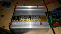
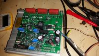
I've redrawn the schematic for readability, though I haven't had a chance to clean up all the parts references and values . The main changes from the earlier versions are:
Range limit for the PLL: The 74HC4046 and especially the 74HC4046A has some strange behavior near the ends of the VCO input voltage range, unlike the classic 4046. This is mentioned in the datasheet, and it can lead to the PLL sticking to the ends of the range. Three resistors easily fixes these problems by limiting the VCO input voltage range to within acceptable limits.
Grounding MOSFET for the loop filter: If the VCO goes below around half of Fres, the third harmonic of the bridge voltage tends to excite the tank more than the fundamental does. This gives some strange waveforms across the cap (and in the tank current as well) with multiple zero crossings per period. This can lead to the PLL sticking to the end of the range. The obvious solution is to limit the lock range of the PLL so that it can never go low enough in frequency to be a problem, but I want a wide range of operating frequencies without changing component values, so I tried this approach instead. The idea is that the MOSFET puts the loop filter in a known state during shutdown, so that the heater always starts up above Fres when turning it on.
Isolated capacitor voltage sensing: I initially wanted to use tank current sensing for PLL phase feedback, but this turned out to be difficult to get working well in practice. The reason I wanted this is that the current sensing is isolated by default, so that I could use the heater with non-isolated tank circuits without having to float the control electronics at mains potential. I found some widely available and cheap digital audio isolation transformers (Murata DA103C) that allow for isolated capacitor voltage sensing. This allows the tank circuit to be isolated or mains-referenced, while having the low voltage control part galvanically isolated from mains in all cases. The voltage sensing circuit has been designed to provide minimal phaseshift for small and large signals and a wide range of frequencies, while not saturating the DA103C.
Wolfram, Tue Sept 22 2015, 10:19PM
Progress is slow but steady.
I received the third revision prototype boards earlier this summer, and populated one for testing. I've finally gotten around to testing it and everything seems to work as it should. I'm still not sure if I'm happy with the way the transistors are mounted, but it works for now. For an eventual final version, I'd like to be able to easily mount a water cooling block to the transistors and mechanically support everything with a minimal amount of mounting hardware.


I've redrawn the schematic for readability, though I haven't had a chance to clean up all the parts references and values
 . The main changes from the earlier versions are:
Range limit for the PLL: The 74HC4046 and especially the 74HC4046A has some strange behavior near the ends of the VCO input voltage range, unlike the classic 4046. This is mentioned in the datasheet, and it can lead to the PLL sticking to the ends of the range. Three resistors easily fixes these problems by limiting the VCO input voltage range to within acceptable limits.
Grounding MOSFET for the loop filter: If the VCO goes below around half of Fres, the third harmonic of the bridge voltage tends to excite the tank more than the fundamental does. This gives some strange waveforms across the cap (and in the tank current as well) with multiple zero crossings per period. This can lead to the PLL sticking to the end of the range. The obvious solution is to limit the lock range of the PLL so that it can never go low enough in frequency to be a problem, but I want a wide range of operating frequencies without changing component values, so I tried this approach instead. The idea is that the MOSFET puts the loop filter in a known state during shutdown, so that the heater always starts up above Fres when turning it on.
Isolated capacitor voltage sensing: I initially wanted to use tank current sensing for PLL phase feedback, but this turned out to be difficult to get working well in practice. The reason I wanted this is that the current sensing is isolated by default, so that I could use the heater with non-isolated tank circuits without having to float the control electronics at mains potential. I found some widely available and cheap digital audio isolation transformers (Murata DA103C) that allow for isolated capacitor voltage sensing. This allows the tank circuit to be isolated or mains-referenced, while having the low voltage control part galvanically isolated from mains in all cases. The voltage sensing circuit has been designed to provide minimal phaseshift for small and large signals and a wide range of frequencies, while not saturating the DA103C.
Re: Adventures in induction heating
Wolfram, Tue Oct 06 2015, 09:40AM
I've discovered a new problem with using PLLs for resonant tank control, and this could well explain problems that other members have had with PLLs for the control of induction heaters and *SSTCs. Specifically, the problem relates to the use of XOR phase comparators with resonant tank circuits.
If you look at the phase between the voltage and current for an LC tank circuit, it starts out at - 90 degrees, passes through 0 degrees at resonance, and ends up at + 90 degrees. This covers a 180 degree range, and if the Q is high, most of this phase change happens over a narrow frequency range.
The XOR phase detector also covers a range of 180 degrees, from 0 to 180 degrees. Going beyond this range, the output voltage (duty cycle) of the phase comparator wraps around; the output is the same for 181 degrees as for 179 degrees, and likewise for 1 and -1 degrees.
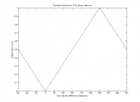
Ideally, using this phase comparator should work if its phase range is centered around the phase range of the tank circuit. In my circuit I do it by sensing the tank capacitor voltage relative to the bridge output voltage (actually the bridge drive signal. The additional 90 degree phase shift between the tank cap voltage and current nicely puts the tank phase range right on top of the phase detector range.
The problem appears if there is any additional phase shift anywhere in the circuit, for example in the capacitor voltage sensing divider or in the gate drivers. Now, the sensed phase can go outside of the range for the phase detector. This gives the transfer function an inflection point, which leads to the PLL sticking at one end of its frequency range.
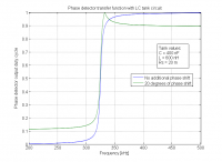
I've done some simulations of this, here's a graph showing the result with 20 degrees of additional phase shift in the feedback network. If the frequency for any reason ends up above the inflection point, the negative feedback will turn into positive feedback, and the frequency will stick to the top of the range. I chose 20 degrees in my simulation to make the problem clear, but this happens with much smaller phase shifts as well. Even with 5 degrees there's a very visible inflection point that will inevitably lead to sticking. And the inherent delay of the gate drivers and IGBTs gives about this much phase shift at 300kHz.
I looked into making a phase detector with a wider input range, but it seems like this is fundamentally impossible without using edge-triggered circuits. So where do we go from here? The pulse density modulation works wonderfully, so I only need to find a new way to control the switching. Here are my ideas so far, sorted in order of preference:
1: Use an edge-triggered phase detector. I could use the built-in phase detector 2 of the 74HC4046A. Edge triggered detectors are not really a good idea around noisy power electronics, but some filtering might be enough to make it work well. I will try to test this within the next few days.
Dr. Dark Current discovered a problem with the 4046 PC2, nicely documented in this thread: . The problem is that this phase comparator has 12 internal states, and it can get very confused when a pulse goes missing when both inputs are driven from the output (one directly, the other through the bridge and the tank). The 74HC4046A has the simpler PC2 with only 3 internal states, so this should not be a problem. Note that the 74HC4046 (non-A version) also has the problematic 12-state PD2. It's importat to be aware that 4046, 74HC4046 and 74HC4046A are three very different chips with major differences in functionality and behavior.
2: Put a microcontroller in the phase loop and program it to avoid the inflection point. I originally wanted to avoid using programmed components in the controller to make it easier to understand and replicate, but if this is what it takes to make it work, then I'll do it. An added bonus is that I can also add overtemperature sensing into the microcontroller and a few other useful features, I just have to be careful so that feature creep does not get out of hand.
3: Use a self-oscillating driver with phase lead. I will try this if all else fails.
Wolfram, Tue Oct 06 2015, 09:40AM
I've discovered a new problem with using PLLs for resonant tank control, and this could well explain problems that other members have had with PLLs for the control of induction heaters and *SSTCs. Specifically, the problem relates to the use of XOR phase comparators with resonant tank circuits.
If you look at the phase between the voltage and current for an LC tank circuit, it starts out at - 90 degrees, passes through 0 degrees at resonance, and ends up at + 90 degrees. This covers a 180 degree range, and if the Q is high, most of this phase change happens over a narrow frequency range.
The XOR phase detector also covers a range of 180 degrees, from 0 to 180 degrees. Going beyond this range, the output voltage (duty cycle) of the phase comparator wraps around; the output is the same for 181 degrees as for 179 degrees, and likewise for 1 and -1 degrees.

Ideally, using this phase comparator should work if its phase range is centered around the phase range of the tank circuit. In my circuit I do it by sensing the tank capacitor voltage relative to the bridge output voltage (actually the bridge drive signal. The additional 90 degree phase shift between the tank cap voltage and current nicely puts the tank phase range right on top of the phase detector range.
The problem appears if there is any additional phase shift anywhere in the circuit, for example in the capacitor voltage sensing divider or in the gate drivers. Now, the sensed phase can go outside of the range for the phase detector. This gives the transfer function an inflection point, which leads to the PLL sticking at one end of its frequency range.

I've done some simulations of this, here's a graph showing the result with 20 degrees of additional phase shift in the feedback network. If the frequency for any reason ends up above the inflection point, the negative feedback will turn into positive feedback, and the frequency will stick to the top of the range. I chose 20 degrees in my simulation to make the problem clear, but this happens with much smaller phase shifts as well. Even with 5 degrees there's a very visible inflection point that will inevitably lead to sticking. And the inherent delay of the gate drivers and IGBTs gives about this much phase shift at 300kHz.
I looked into making a phase detector with a wider input range, but it seems like this is fundamentally impossible without using edge-triggered circuits. So where do we go from here? The pulse density modulation works wonderfully, so I only need to find a new way to control the switching. Here are my ideas so far, sorted in order of preference:
1: Use an edge-triggered phase detector. I could use the built-in phase detector 2 of the 74HC4046A. Edge triggered detectors are not really a good idea around noisy power electronics, but some filtering might be enough to make it work well. I will try to test this within the next few days.
Dr. Dark Current discovered a problem with the 4046 PC2, nicely documented in this thread:
 . The problem is that this phase comparator has 12 internal states, and it can get very confused when a pulse goes missing when both inputs are driven from the output (one directly, the other through the bridge and the tank). The 74HC4046A has the simpler PC2 with only 3 internal states, so this should not be a problem. Note that the 74HC4046 (non-A version) also has the problematic 12-state PD2. It's importat to be aware that 4046, 74HC4046 and 74HC4046A are three very different chips with major differences in functionality and behavior.
2: Put a microcontroller in the phase loop and program it to avoid the inflection point. I originally wanted to avoid using programmed components in the controller to make it easier to understand and replicate, but if this is what it takes to make it work, then I'll do it. An added bonus is that I can also add overtemperature sensing into the microcontroller and a few other useful features, I just have to be careful so that feature creep does not get out of hand.
3: Use a self-oscillating driver with phase lead. I will try this if all else fails.
Re: Adventures in induction heating
Victor.Mello, Sun Nov 01 2015, 11:33PM
Wolfram thank you for sharing!
I already spent 5 years dating my induction heater lol, it's coming alive (In it's first good looking build) until the end of the year!
I tried the 4046 chip gave up on it along time ago, I'm now perfecting the code for the AT90PWM316 chip, what do you think of this chip?
I aiming to do a 110 - 220V with a switch to change the number of winding on the core (series resonant).
The power control, I thought to PWM the resonant frequency with the AT90.
Here are some photos of what I'm building:
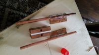
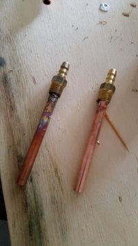
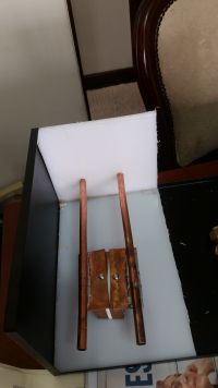
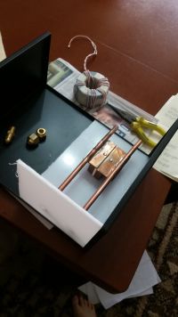
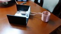
Old coil and new coil comparison
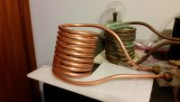
And here's my previous one running (this one is just a frequency generator controlling a h-bridge):
Do you have any suggestions??
Thanks again!
Victor.Mello, Sun Nov 01 2015, 11:33PM
Wolfram thank you for sharing!
I already spent 5 years dating my induction heater lol, it's coming alive (In it's first good looking build) until the end of the year!
I tried the 4046 chip gave up on it along time ago, I'm now perfecting the code for the AT90PWM316 chip, what do you think of this chip?
I aiming to do a 110 - 220V with a switch to change the number of winding on the core (series resonant).
The power control, I thought to PWM the resonant frequency with the AT90.
Here are some photos of what I'm building:


Old coil and new coil comparison


And here's my previous one running (this one is just a frequency generator controlling a h-bridge):
Do you have any suggestions??
Thanks again!
Re: Adventures in induction heating
parasole, Sat Nov 14 2015, 07:53PM
Would be interested to see the code, of course if you will consider to share it...
I am planning similar setup, my intention is to use phase shifting for power control...
parasole, Sat Nov 14 2015, 07:53PM
Victor.Mello wrote ...
perfecting the code for the AT90PWM316
perfecting the code for the AT90PWM316
Would be interested to see the code, of course if you will consider to share it...
I am planning similar setup, my intention is to use phase shifting for power control...
Re: Adventures in induction heating
Wolfram, Thu Nov 19 2015, 04:55PM
PLL discussion has been moved to a separate thread and a good solution has been found.
Hey Victor.
Very nice project, looks like a solid build. You should make a separate thread about your project, then I (and others) can can discuss it without going off-topic here. If you start a new thread in the projects forum, I can move my reply to that thread.
One of the main challenges in driving an induction heater is the fact that a well designed tank circuit usually has a very high Q factor, often exceeding 100. This means that even a small frequency change around the resonant frequency leads to a large change in the switching phase angle. The AT90PWM316 PWM module can be clocked at up to 64 MHz. This gives an acceptable frequency resolution with tanks resonating at 50 kHz for example, but above 100 kHz or so, the frequency resolution tends to become a bit rough for accurate switching phase angle control, leading to increased switching losses. The AT90PWM supports a mode with finer frequency resolution, but this mode adds phase jitter so it's not really usable in this application. In conclusion, whether or not it is a usable solution depends on the frequency you want to operate at. For my heater I want to be able to work at higher frequencies (up to several MHz) so I didn't go with this option. As I'm using IGBTs up to half a megahertz (and hopefully beyond), accurate switching angle control is essential to keep losses low.
It also depends on what power control scheme you're going for. If you chose frequency control (detuning above resonance), it doesn't make much sense to minimize switching losses as it will only run at resonance when heavily loaded (and the Q is low), and switching losses will be high in any case. PWM will also increase the switching losses, but if you're operating at low frequency and moderate power you might get away with it.
I'm considering using a microcontroller myself, but to get accurate enough frequency control at high frequencies I have to clock the microcontroller from an analog PLL and phase-lock it to a multiple of the tank resonant frequency.
What IGBT series are you using by the way? Your setup looks very similar to a medium frequency (50 kHz) setup I'm working on.
Wolfram, Thu Nov 19 2015, 04:55PM
PLL discussion has been moved to a separate thread
 and a good solution has been found.
Victor.Mello wrote ...
Wolfram thank you for sharing!
I already spent 5 years dating my induction heater lol, it's coming alive (In it's first good looking build) until the end of the year!
I tried the 4046 chip gave up on it along time ago, I'm now perfecting the code for the AT90PWM316 chip, what do you think of this chip?
I aiming to do a 110 - 220V with a switch to change the number of winding on the core (series resonant).
The power control, I thought to PWM the resonant frequency with the AT90.
Hey Victor.
Very nice project, looks like a solid build. You should make a separate thread about your project, then I (and others) can can discuss it without going off-topic here. If you start a new thread in the projects forum, I can move my reply to that thread.
One of the main challenges in driving an induction heater is the fact that a well designed tank circuit usually has a very high Q factor, often exceeding 100. This means that even a small frequency change around the resonant frequency leads to a large change in the switching phase angle. The AT90PWM316 PWM module can be clocked at up to 64 MHz. This gives an acceptable frequency resolution with tanks resonating at 50 kHz for example, but above 100 kHz or so, the frequency resolution tends to become a bit rough for accurate switching phase angle control, leading to increased switching losses. The AT90PWM supports a mode with finer frequency resolution, but this mode adds phase jitter so it's not really usable in this application. In conclusion, whether or not it is a usable solution depends on the frequency you want to operate at. For my heater I want to be able to work at higher frequencies (up to several MHz) so I didn't go with this option. As I'm using IGBTs up to half a megahertz (and hopefully beyond), accurate switching angle control is essential to keep losses low.
It also depends on what power control scheme you're going for. If you chose frequency control (detuning above resonance), it doesn't make much sense to minimize switching losses as it will only run at resonance when heavily loaded (and the Q is low), and switching losses will be high in any case. PWM will also increase the switching losses, but if you're operating at low frequency and moderate power you might get away with it.
I'm considering using a microcontroller myself, but to get accurate enough frequency control at high frequencies I have to clock the microcontroller from an analog PLL and phase-lock it to a multiple of the tank resonant frequency.
What IGBT series are you using by the way? Your setup looks very similar to a medium frequency (50 kHz) setup I'm working on.
Re: Adventures in induction heating
Steve Ward, Mon Nov 23 2015, 08:34AM
With regards to microcontroller drive, you should consider the idea that the PWM frequency need not be "constant", but can dither between 2 frequencies to produce, on average, whatever frequency you want. There is nothing, in a practical sense, bad about there being some jitter in the switch timing. For example, my digital tesla coil drivers operate from a 64MHZ clocked MCU, but they can track resonant circuits up to 500khz with very nice timing in terms of power switching. It just amounts to some switching happening a little early or a little late (give or take 15nS, one clock period) from the "perfect" timing. No need to mess with the clock source of the MCU, just constantly tweak the PWM period to track the desired period.
Its somewhat trivial to feedback the inverter current to the MCU and trigger its PWM timing from the current zero crossings so that the MCU PWM will track the resonant frequency of the system. You can basically make a "digital PLL" this way, and adjust the phasing of the gate drive signal with the MCU to control power if you want. Just sayin, its been done and works .
.
Steve Ward, Mon Nov 23 2015, 08:34AM
With regards to microcontroller drive, you should consider the idea that the PWM frequency need not be "constant", but can dither between 2 frequencies to produce, on average, whatever frequency you want. There is nothing, in a practical sense, bad about there being some jitter in the switch timing. For example, my digital tesla coil drivers operate from a 64MHZ clocked MCU, but they can track resonant circuits up to 500khz with very nice timing in terms of power switching. It just amounts to some switching happening a little early or a little late (give or take 15nS, one clock period) from the "perfect" timing. No need to mess with the clock source of the MCU, just constantly tweak the PWM period to track the desired period.
Its somewhat trivial to feedback the inverter current to the MCU and trigger its PWM timing from the current zero crossings so that the MCU PWM will track the resonant frequency of the system. You can basically make a "digital PLL" this way, and adjust the phasing of the gate drive signal with the MCU to control power if you want. Just sayin, its been done and works
 .
.Re: Adventures in induction heating
Wolfram, Mon Nov 23 2015, 03:40PM
I did some simulations which showed pretty discouraging results. With an oscillator frequency of 64 MHz, the frequency step size around 500 kHz is 4 kHz, and this corresponds with a phase angle difference of 70 degrees when the tank Q is 100 (which seems to be pretty typical for an unloaded IH tank from my measurements). As you've reported that it works well in practice, it can't be as bad as my simulation suggests.
Is the actual switching phase angle averaged by the L/R time constant of the tank circuit? It does seem to make sense, and if it is true then the microcontroller as a VCO is a much more viable alternative than I first suspected.
Re: Adventures in induction heating
Steve Ward, Mon Nov 23 2015, 04:37PM
I think you missed my point [edit: upon reading your response, it seems like you did get it, but i already wrote this anyway], I will try to clarify.
It's true that if you kept a constant PWM output frequency from your 64MHz source that you would *very likely* end up with a large phase error because you cannot hit the exact frequency with any integer divider from that 64MHz source. The idea I'm trying to convey is to continually change the PWM output frequency, say, between the 2 nearest frequency values, one above Fres, the other below Fres, so that the frequency on average is exactly Fres (or whatever you want). With a 64MHZ clock you get 15.625nS per clock tick, so its possible to keep your power switch transitions within just 15.625nS of the ideal switching time, which for most power conversion system is a negligible amount of error when the half period is >1uS.
Another way to see it is that because of the discrete steps in output frequency, the PWM signal will accumulate phase lead or lag depending on if its above or below the resonant frequency of the heater circuit. The task for the MCU is to constantly update the PWM frequency so that the phase lead or lag never accumulates too far. Theoretically its possible to keep the phase error to be within 1 clock period, or just ~15nS of perfection.
My next point was that you can feedback the current signal (via comparator, so its a 1-bit digital timing signal) to the MCU. In my experience, simply measuring the oscillation period of the tank current and outputting that frequency does not quite work... it tends to settle with some significant phase error. The more useful technique, i find, is to use the current feedback signal to reset what is essentially a 1-shot timer, which is programmed with a period just less than the period of 1/2 cycle of Fres. The output transition from this 1-shot timer would cause the PWM signal to the h-bridge to transition. You can gain phase by shortening the period of this 1-shot timer. Note that this scheme does not necessarily fit into the typical operating conditions of most MCU's timer peripherals, so you'd have to be creative and likely use some external logic to convert your 1-shot pulse generator into a PWM signal that changes state when triggered by this 1-shot. Essentially, you create a phase-leading signal by delaying the feedback signal by 1/2 cycle (really, some amount less than 1/2 cycle). The reason this can work so well is because the MCU can measure the timing of the feedback signals period, and calculate the desired period of the 1-shot for optimal control. The last bit of this "solution" is that initially the MCU must start driving the LC tank "open loop" style at some frequency close enough to Fres to get this current feedback signal to lock on to.
From here you can hopefully see how you could implement power control via variable phase lead, or do more complex things like blank out PWM pulses for "pulse skip modulation". However, most generic MCU timer peripherals will not support these more exotic schemes on their own, so you'd be better off adding some CPLD with a cheap MCU, or using an FPGA or other "SoC" (system on chip) solutions that offer programmable logic devices on board to implement the PWM logic.
An arguably simpler idea is to have the MCU search for the best frequency to drive based on phase information. You could make a simple phase comparator by XORing the 1-bit current feedback signal with your PWM output signal, RC filtering this and feeding it into an ADC. The MCU would then have a phase-error signal it could work to try and keep at some specified value. This solution should be much more appropriate for induction heating over Tesla coils, since the resonant frequency is not expected to change quickly, and some hard-switching is tolerated if it did suddenly change quickly (say you short out a turn on your work coil...).
Re: Adventures in induction heating
Uspring, Mon Nov 23 2015, 07:00PM
Frequency dithering doesn't look too bad to me. Consider as the simplest case: A full sine period of length T1 followed by a full sine period of length T2 and then repeat from the beginning. This signal is strictly periodical with the period T1+T2, so in the frequency domain it consists of multiples of the frequency 1/(T1+T2). If T1 and T2 are close to each other, the major component will be 2/(T1+T2). To a much lesser extent, energy will be in the frequencies 1/(T1+T2), 3/(T1+T2), 4/(T1+T2) etc. I haven't done the math, but I think, the closer T1 and T2 are, the smaller are the non major components.
You won't always be at your favourite phase, but the phase error due to dithering will always be less than say 16ns/2us * 360 degrees (i.e. resolution/period * 360 degrees).
For other dithering modes (i.e. longer periods than T1+T2), the weaker frequency components might not be so far away from the major one, but they become weaker as they approach the major component.
Re: Adventures in induction heating
GeordieBoy, Tue Nov 24 2015, 09:43PM
Have you guys thought about using Direct Digital Synthesis (DDS) ?
DDS chips are available that generate a *SINEWAVE* at a programmable frequency. These often generate a discrete (sampled) sinewave up to several tens of MHz, with a frequency resolution in the milli-Hertz step range, when running from a clock frequency of 100MHz or so. (You can even get down to micro-Hertz accuracy if necessary, as we do at work for driving high-Q MEMS resonators.)
DDS chips from Analog Devices cost a few Euros each and you program the frequency and phase from a microcontroller via SPI. They are very common with the amateur radio crowd to replace VCOs in their VFOs and they're also used in high-end stuff like phase-array radars, dopler ultrasound, etc. They often have lower noise and spurs than a VCO wrapped inside a PLL. This is what I have used in induction heating applications where I wanted fine frequency control under microprocessor command.
The important thing to do here, is to synthesise a sinewave with the DDS. This is initially a discrete "stepped" (sampled) sinewave at some high sample rate like 50MHz. But you pass this through an anti-imaging (reconstruction) low-pass filter that removes all the high-frequency energy from the sampling process and leaves you with a beautifully clean sinewave. Then you put this through a comparator to give you a square wave if that is the waveform you ultimately want to drive your power electronics. This process i've described is important to remove the jitter, as just attempting to generate a digital square wave "clock" signal directly using DDS results in bad period jitter equal to the reciprocal of the sample-rate.
An additional benefit of first synthesising the sinewave is that you can pass this into two comparators with slightly different decision thresholds in order to implement deadtime control for driving opposing devices in power electronics switching applicaitons.
Just another tool to keep in the box for when it might come in handy that I have found very effective. Analog Devices have some good App Notes on DDS for those interested.
-Richie Burnett,
Re: Adventures in induction heating
parasole, Fri Nov 27 2015, 07:57AM
You still will need a reliable frequency and phase measurement of resonant tank in order to adjust the DDS, this is the main challenge... Second challenge is output power regulation...
parasole, Fri Nov 27 2015, 07:57AM
GeordieBoy wrote ...
Have you guys thought about using Direct Digital Synthesis (DDS) ?
Have you guys thought about using Direct Digital Synthesis (DDS) ?
You still will need a reliable frequency and phase measurement of resonant tank in order to adjust the DDS, this is the main challenge... Second challenge is output power regulation...
Re: Adventures in induction heating
Wolfram, Fri Nov 27 2015, 12:29PM
Agreed. These two were the main challenges I had during this project, everything else was pretty straightforward in comparison. I chose to do a plain analog + logic implementation for simplicity and ease of understanding, but the solutions I ended up with can also be implemented in an FPGA or a (fast enough) microcontroller.
For the phase detector, I had lots of trouble with XOR and edge detector ones, until I discovered this: . After I implemented that one, I haven't had any problems (yet).
For the power control, I ended up with pulse density modulation with mains tracking. This control scheme has tons of benefits, like ZVS and near-ZCS under all loading conditions and perfect mains power factor. There are some excellent papers on this control scheme, particularly this and this
I use the pulse density modulation to keep the inverter curent at a fixed fraction of the DC bus voltage. Changing this fraction changes the power level. Doing this ensures that the current draw is always proportional to bus voltage, so the power factor is perfect. The pulse density stays the same throughout the mains cycle, as long as the loading is the same. With no load placed in the coil, the power draw is low and dominated by resistive losses in the tank coil. As a load is placed in the coil, the pulse density increases and mains current draw increases, while the tank current stays constant. When the loading is so high that the pulse density becomes 100%, power throughput is at a maximum value. If the loading is increased further, tank current and mains current draw decreases again. If a tapped matching inductor or transformer is used, the loading level at which maximum power transfer happens can be changed.
Thanks for the insight, that's clever. At the frequencies I'm working with now it's not too critical, but this will be very useful as I go to higher frequencies. I notice that some of the common DDS chips from AD have the comparator built-in, so it should be pretty clean to implement as well.
Wolfram, Fri Nov 27 2015, 12:29PM
parasole wrote ...
You still will need a reliable frequency and phase measurement of resonant tank in order to adjust the DDS, this is the main challenge... Second challenge is output power regulation...
You still will need a reliable frequency and phase measurement of resonant tank in order to adjust the DDS, this is the main challenge... Second challenge is output power regulation...
Agreed. These two were the main challenges I had during this project, everything else was pretty straightforward in comparison. I chose to do a plain analog + logic implementation for simplicity and ease of understanding, but the solutions I ended up with can also be implemented in an FPGA or a (fast enough) microcontroller.
For the phase detector, I had lots of trouble with XOR and edge detector ones, until I discovered this:
 . After I implemented that one, I haven't had any problems (yet).
For the power control, I ended up with pulse density modulation with mains tracking. This control scheme has tons of benefits, like ZVS and near-ZCS under all loading conditions and perfect mains power factor. There are some excellent papers on this control scheme, particularly this
 and this
I use the pulse density modulation to keep the inverter curent at a fixed fraction of the DC bus voltage. Changing this fraction changes the power level. Doing this ensures that the current draw is always proportional to bus voltage, so the power factor is perfect. The pulse density stays the same throughout the mains cycle, as long as the loading is the same. With no load placed in the coil, the power draw is low and dominated by resistive losses in the tank coil. As a load is placed in the coil, the pulse density increases and mains current draw increases, while the tank current stays constant. When the loading is so high that the pulse density becomes 100%, power throughput is at a maximum value. If the loading is increased further, tank current and mains current draw decreases again. If a tapped matching inductor or transformer is used, the loading level at which maximum power transfer happens can be changed.
Just another tool to keep in the box for when it might come in handy that I have found very effective. Analog Devices have some good App Notes on DDS for those interested.
Thanks for the insight, that's clever. At the frequencies I'm working with now it's not too critical, but this will be very useful as I go to higher frequencies. I notice that some of the common DDS chips from AD have the comparator built-in, so it should be pretty clean to implement as well.
Re: Adventures in induction heating
Wolfram, Mon Dec 21 2015, 01:45AM
My design has been split into two boards. In the previous revision I was running out of space on the 10x10 cm standard size for cheap PCBs, and these boards are so much cheaper than a larger form factor. I then realized that it makes a lot of sense to split up the design in two boards. One board is the control board, and the other board contains the bridge and everything else mains-connected. This will allow different bridges to be used with the same control board, so that a wide variety of power levels and frequencies can be accomodated by using different bridge boards. It will also allow the same bridges to be re-used if a new control board is made in the future.
For now I have started working on the control board, which is based on my old circuit but with a lot of improvements as outlined below. I have already completed one medium-power bridge board which is similar to my previous version, with the goal of delivering 4 kW at several hundred kilohertz. I will also make a second output board for driving IGBT bricks, for delivering tens of kilowatts at up to 100 kHz or so.
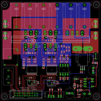
Here's a a screenshot of the 4 kW power board. The bridge thermal management is inpired by a design by Steve Ward which can be seen here:
A new phase detector has been implemented, as described in this thread: . This has already been implemented in my prototype and it solved my earlier problems of occasional PLL lockup
The circuit has also been modified to provide a phase lead for the switching instead of a fixed phase shift. This has some advantages, as the PLL compensates for delays in the IGBTs and gate drivers. Since the delay is independent of the frequency now, it should give optimal switching over a wider frequency range.
The circuit for tank current phase sensing has been improved. With the new phase detector, primary current phase needs to be sensed accurately and the old circuit was simply not good enough. The new circuit has enough dynamic range to acquire lock at low input voltage while still working correctly with minimal dissipation at full power.
Tank current phase is now sensed separately from the bridge current. This allows my driver to work seamlessly with isolated and non-isolated LCLR as well as both transformer-coupled and non-isolated series resonant. This could be made to work in my old circuit as well, but with some compromises when running LCLR. The two dollars it costs for the second CT makes this a cheap and useful feature. The separate CTs also significantly improves the performance it is possible to get from the phase sensing CT.
The gate drive enable circuit for PDM has been revised. The old one had some trouble with glitches on the output due to differences in propagation delays between different logic paths, a classic race condition problem. The old circuit was based on disabling the gate drive signal with logic, as done in both the classic Ward and Conner *SSTC drivers, and this works perfectly most of the time. The problems were caused by my gate drivers, which react very fast. The 20 ns glitch pulses, which would never have made it through a classic GDT, triggered a dead-time period in my Silabs drivers. During this dead-time, the bridge output voltage naturally commutates towards the positive rail, but after the dead-time is over the low IGBT turns on again. This problem was solved by going for purely synchronous logic in the enable chain, costing a total of 20 cents in extra parts.

This scope shot (taken with a camera as I had no USB stick handy) shows the problem. The purple trace shows the bridge output current. The blue trace shows one of the bridge outputs. When the bottom IGBTs are turned on for pulse skipping, a small glitch gets through the enable gate due to a logic race condition. This triggers a dead-time period, where the bridge voltage commutates to the DC rail. When the dead-time is over, the lower IGBT turns on again and slams the output voltage to ground, generating some noise. The new solution avoids this by using synchronous logic
Wolfram, Mon Dec 21 2015, 01:45AM
My design has been split into two boards. In the previous revision I was running out of space on the 10x10 cm standard size for cheap PCBs, and these boards are so much cheaper than a larger form factor. I then realized that it makes a lot of sense to split up the design in two boards. One board is the control board, and the other board contains the bridge and everything else mains-connected. This will allow different bridges to be used with the same control board, so that a wide variety of power levels and frequencies can be accomodated by using different bridge boards. It will also allow the same bridges to be re-used if a new control board is made in the future.
For now I have started working on the control board, which is based on my old circuit but with a lot of improvements as outlined below. I have already completed one medium-power bridge board which is similar to my previous version, with the goal of delivering 4 kW at several hundred kilohertz. I will also make a second output board for driving IGBT bricks, for delivering tens of kilowatts at up to 100 kHz or so.

Here's a a screenshot of the 4 kW power board. The bridge thermal management is inpired by a design by Steve Ward which can be seen here:

A new phase detector has been implemented, as described in this thread:
 . This has already been implemented in my prototype and it solved my earlier problems of occasional PLL lockup
The circuit has also been modified to provide a phase lead for the switching instead of a fixed phase shift. This has some advantages, as the PLL compensates for delays in the IGBTs and gate drivers. Since the delay is independent of the frequency now, it should give optimal switching over a wider frequency range.
The circuit for tank current phase sensing has been improved. With the new phase detector, primary current phase needs to be sensed accurately and the old circuit was simply not good enough. The new circuit has enough dynamic range to acquire lock at low input voltage while still working correctly with minimal dissipation at full power.
Tank current phase is now sensed separately from the bridge current. This allows my driver to work seamlessly with isolated and non-isolated LCLR as well as both transformer-coupled and non-isolated series resonant. This could be made to work in my old circuit as well, but with some compromises when running LCLR. The two dollars it costs for the second CT makes this a cheap and useful feature. The separate CTs also significantly improves the performance it is possible to get from the phase sensing CT.
The gate drive enable circuit for PDM has been revised. The old one had some trouble with glitches on the output due to differences in propagation delays between different logic paths, a classic race condition problem. The old circuit was based on disabling the gate drive signal with logic, as done in both the classic Ward and Conner *SSTC drivers, and this works perfectly most of the time. The problems were caused by my gate drivers, which react very fast. The 20 ns glitch pulses, which would never have made it through a classic GDT, triggered a dead-time period in my Silabs drivers. During this dead-time, the bridge output voltage naturally commutates towards the positive rail, but after the dead-time is over the low IGBT turns on again. This problem was solved by going for purely synchronous logic in the enable chain, costing a total of 20 cents in extra parts.

This scope shot (taken with a camera as I had no USB stick handy) shows the problem. The purple trace shows the bridge output current. The blue trace shows one of the bridge outputs. When the bottom IGBTs are turned on for pulse skipping, a small glitch gets through the enable gate due to a logic race condition. This triggers a dead-time period, where the bridge voltage commutates to the DC rail. When the dead-time is over, the lower IGBT turns on again and slams the output voltage to ground, generating some noise. The new solution avoids this by using synchronous logic
Re: Adventures in induction heating
Steve Ward, Fri Dec 25 2015, 10:51PM
Have you tried running that gate driver circuit without any negative bias on the gates? I've been tempted to do this for some time now, but i usually end up designing in some negative bias to be sure there won't be a problem, but this is costly as it requires an isolated supply for each transistor (at least i couldn't come up with a boot-strap solution). I'll be interested to see the results, perhaps you've already demonstrated that this drive scheme is fine and does not suffer from dv/dt induced gate turn on?
Re: Adventures in induction heating
Wolfram, Tue Dec 29 2015, 06:03PM
Initially I wanted to see if I could get away with running without negative gate bias, and it worked so well that I've stuck with it through all revisions so far. Drain dV/dt is limited as I have soft switching in the bridge, but I don't notice any signs of dV/dt induced turn-on even when I adjust the switching phase angle so that I lose ZVS, apart from the regular miller plateu.
For the brick-driver add-on, I'm looking into using the MGJ2D-series of DC/DC converters from Murata, with a negative bias output, as I want to play it safe.
Wolfram, Tue Dec 29 2015, 06:03PM
Steve Ward wrote ...
Have you tried running that gate driver circuit without any negative bias on the gates? I've been tempted to do this for some time now, but i usually end up designing in some negative bias to be sure there won't be a problem, but this is costly as it requires an isolated supply for each transistor (at least i couldn't come up with a boot-strap solution). I'll be interested to see the results, perhaps you've already demonstrated that this drive scheme is fine and does not suffer from dv/dt induced gate turn on?
Have you tried running that gate driver circuit without any negative bias on the gates? I've been tempted to do this for some time now, but i usually end up designing in some negative bias to be sure there won't be a problem, but this is costly as it requires an isolated supply for each transistor (at least i couldn't come up with a boot-strap solution). I'll be interested to see the results, perhaps you've already demonstrated that this drive scheme is fine and does not suffer from dv/dt induced gate turn on?
Initially I wanted to see if I could get away with running without negative gate bias, and it worked so well that I've stuck with it through all revisions so far. Drain dV/dt is limited as I have soft switching in the bridge, but I don't notice any signs of dV/dt induced turn-on even when I adjust the switching phase angle so that I lose ZVS, apart from the regular miller plateu.
For the brick-driver add-on, I'm looking into using the MGJ2D-series of DC/DC converters from Murata, with a negative bias output, as I want to play it safe.
Print this page