
High Voltage Planar Ferrite transformers. ( Intial Experiments )
Patrick, Sun Aug 31 2014, 04:21AMHigh Voltage Planar Ferrite transformers. ( Intial Experiments )
Purpose :
To verify some ideas i have on SMPS transformers for aircraft and spacecraft power conversion ( specifically needed since fuel cells and solar cells can't be seriesed past some practical point ). I plan to develop high power, small, high effciency power supplies. Heating, reliability and mass are the primary concerns, though keeping the turns ratio down is also important.
Primary:
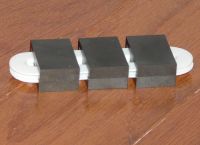
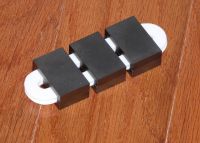
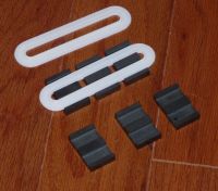
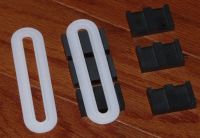
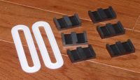
The device below will have a copper foil primary of less than a single skin depth to avoid proximity effects at high frequency, insulated with Kapton film. There is also a thin copper foil grounded grading plane around the center post of the ferrite.
Secondary:
A secondary of very thin 0.007" enamel wire. The secondary is meant to have many volts per turn (due to ferrite core area), which are in an insulated groove, as JPsmith and I demonstrated years ago. The secondary turns will be epoxy potted. The wire i have is "double enamled" 0.0056" copper diameter, maikng it 35 AWG. Im aiming for about 40kV, dont know yet if i can from 312 turns.
Ferrite and Bobbin:
The Bobbin will be 3D printed in the future from bright blue PLA as it has a 15kV / mil dielectric strength, so at 5kv per mil, my bobbin should insulate to 90-120kV. The whole transformer will be submerged in Canola oil for insulation and cooling. I wanted the surface area of the ferrite to increase faster than volume when scaled as a function of power, for thermal dissipation, so that drove me to the TSC companies planar cores. Bmax is 2000 Guass, as ferrites typically saturate at 3000 Guass. The core will swing 4000 Guass total.
FEMM analysis: to follow!
Principle to be proved:
I may have to series the secondaries, and parallel the primaries to get the voltage on the secondary.These primaries can use multiple TO-247 mosfets instead of the mega CM600 packages, which can have switching issues at the gate, which is physically large with loop area.
Circuit:

(Incomplete) this is a half bridge alternately grounding the two halves of the primaries. Some of these componet values are bogus, just to keep the editor happy.
heat :

 Grooved Bobbins For Segmented Windings (JPsmith's work)
I've got some math to post, but it looks like I'll get 44 Volts per turn, Which might mean 13.7 kv. If i can get to 11kV ill be happy, then i can series 10kv sections to get up to 70kv or so. All the insulation and field-grading has been dimensioned into the design so far. FEMM analysis and a prototype tested to destruction will be used to verifiy this.
Proximity and skin effects worry me most.

Re: High Voltage Planar Ferrite transformers. ( Intial Experiments )
Electra, Mon Sept 01 2014, 10:32PM
Yes but I can't help wonder how you are going to wind it? Or are you going to make a coil on a separate jig and transfer it to the central oval groove afterwards? Is the groove round the outside rim for the primary, perhaps I'm picturing it all wrong.
Is this for very high voltage (like in the realm of flybacks) when you quoted those insulation ratings and thin wire, or just normal SMPSU / inverter applications?
(Edit)
Duh! just read your post again seen you said 40kv must be tired tonight. Tell us more, a flying hv supply or is it part of a bigger plan.
Re: High Voltage Planar Ferrite transformers. ( Intial Experiments )
Patrick, Mon Sept 01 2014, 10:42PM
it will be wound while wet with epoxy, keeping the bubbles out by visual inspection. This is the best i can do till i get a vacuum pump.
the goal is to continue my DeSeversky ionocraft research, MHD high temp thrusters, and laser discharge experiments.


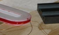
I got way more than 312 turns into this baby! i underestimated the packing effciency, and overestimated the diameter when i estimated 312 turns. Im thinking 400 turns. I dyed the water thin epoxy bright red to verify that bubbles werent being left behind. I had no vacuum pump, but this wet winding was the best i could do at the moment.
ive updated the top post

Patrick, Mon Sept 01 2014, 10:42PM
Electra wrote ...
Yes but I can't help wonder how you are going to wind it? Or are you going to make a coil on a separate jig and transfer it to the central oval groove afterwards? Is the groove round the outside rim for the primary, perhaps I'm picturing it all wrong.
Is this for very high voltage (like in the realm of flybacks) when you quoted those insulation ratings and thin wire, or just normal SMPSU / inverter applications?
(Edit)
Duh! just read your post again seen you said 40kv must be tired tonight. Tell us more, a flying hv supply or is it part of a bigger plan.
ive been editing the post as youve been reeding it, dont feel bad!Yes but I can't help wonder how you are going to wind it? Or are you going to make a coil on a separate jig and transfer it to the central oval groove afterwards? Is the groove round the outside rim for the primary, perhaps I'm picturing it all wrong.
Is this for very high voltage (like in the realm of flybacks) when you quoted those insulation ratings and thin wire, or just normal SMPSU / inverter applications?
(Edit)
Duh! just read your post again seen you said 40kv must be tired tonight. Tell us more, a flying hv supply or is it part of a bigger plan.
it will be wound while wet with epoxy, keeping the bubbles out by visual inspection. This is the best i can do till i get a vacuum pump.
the goal is to continue my DeSeversky ionocraft research, MHD high temp thrusters, and laser discharge experiments.


I got way more than 312 turns into this baby! i underestimated the packing effciency, and overestimated the diameter when i estimated 312 turns. Im thinking 400 turns. I dyed the water thin epoxy bright red to verify that bubbles werent being left behind. I had no vacuum pump, but this wet winding was the best i could do at the moment.
ive updated the top post

Re: High Voltage Planar Ferrite transformers. ( Intial Experiments )
Patrick, Tue Sept 16 2014, 06:48AM
reading this for background :
And I found that a optical feedback from a lower kV secondary will work in my application.
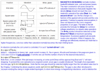
Im using the bi-polar square wave math.
Patrick, Tue Sept 16 2014, 06:48AM
reading this for background :

And I found that a optical feedback from a lower kV secondary will work in my application.

Im using the bi-polar square wave math.
Re: High Voltage Planar Ferrite transformers. ( Intial Experiments )
Thomas W, Tue Sept 16 2014, 01:26PM
Oooh, this is a cool project. At a convention i went to there was a company that specialised in planar transformers, they had one about the size of a cigerette pack that could handle around 40kW IIRC
Can't wait to see how this turns out bud :)
-Thomas
Thomas W, Tue Sept 16 2014, 01:26PM
Oooh, this is a cool project. At a convention i went to there was a company that specialised in planar transformers, they had one about the size of a cigerette pack that could handle around 40kW IIRC
Can't wait to see how this turns out bud :)
-Thomas
Re: High Voltage Planar Ferrite transformers. ( Intial Experiments )
Patrick, Tue Sept 16 2014, 04:26PM
I was hoping for high power like 10kW at some point, im glad im not the only one looking at planars.
Patrick, Tue Sept 16 2014, 04:26PM
I was hoping for high power like 10kW at some point, im glad im not the only one looking at planars.
Re: High Voltage Planar Ferrite transformers. ( Intial Experiments )
hen918, Tue Sept 16 2014, 05:06PM
I was reading somewhere a few years ago that planar transformers were going to give us amazingly high power densities at both high voltage and low voltage. Nice to see them being developed!
hen918, Tue Sept 16 2014, 05:06PM
I was reading somewhere a few years ago that planar transformers were going to give us amazingly high power densities at both high voltage and low voltage. Nice to see them being developed!
Re: High Voltage Planar Ferrite transformers. ( Intial Experiments )
Patrick, Tue Sept 16 2014, 05:11PM
yeah i really started trying to understand the ferrite and its ways, instead of ust going bigger and bigger. and Mag-inc want like 700US$ for their biggest cores, which couldnt do much better than these small planar, but for there better winding volumes. so now its just proving high volts per turn is posssible.
Re: High Voltage Planar Ferrite transformers. ( Intial Experiments )
hen918, Tue Sept 16 2014, 08:05PM
Which also improves efficiency, because you have a higher voltage per turn, you can have less turns, and therefore thicker wire, allowing a greater current and less copper/skin loss
I'll have to look at using one in my switched mode inverter
hen918, Tue Sept 16 2014, 08:05PM
Which also improves efficiency, because you have a higher voltage per turn, you can have less turns, and therefore thicker wire, allowing a greater current and less copper/skin loss
I'll have to look at using one in my switched mode inverter
Re: High Voltage Planar Ferrite transformers. ( Intial Experiments )
Hazmatt_(The Underdog), Wed Sept 17 2014, 01:35AM
For 10KW at high voltage, the winding core is going to need to be totally encased with HV lead-out wire, or its going to eat itself in a bright flash!. The intrenal stresses will have to be considered too. You may need sectional windings to limit the stresses.
You might want to use two sets to double the voltage, and actually use larger E cores so you can stack 4 or 8 bobbins on top of each other in one assembly, just a thought.
Epcos cores are pretty cheap anyway, you could probably get a whole flat of them for $20.
Re: High Voltage Planar Ferrite transformers. ( Intial Experiments )
Patrick, Thu Sept 18 2014, 07:23AM
 previous purchase
 spec sheet, note the "50 all" type saturates at 5,000 guass.
I'll post some math in the morning, but 0.7 x 5,000 = 3,500 guass
 TSC 50 all
Patrick, Thu Sept 18 2014, 07:23AM
 previous purchase
 spec sheet, note the "50 all" type saturates at 5,000 guass.
I'll post some math in the morning, but 0.7 x 5,000 = 3,500 guass
 TSC 50 all
Re: High Voltage Planar Ferrite transformers. ( Intial Experiments )
Patrick, Fri Sept 19 2014, 07:27AM
Im needing others to review my math:
 possible MOSFET
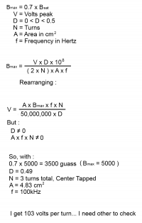
Im operating with +100 Volts through one primary of 1.5 turns, then -100 volts through the other 1.5 turns. the primary is 3 total turns CT is positive.
so im not sure if the 1.5 turns is multiplied or divided ?
EDIT: the more i think (but am not sure) if the core supports 100v per turn then the 1.5 x 100 = 150 V input. so ill put 150 V in positive then 150 V in negative. I think.
So for the secondary, if its 200 turns x 100 V per Turns = 20,000v.
Which means:
-100v in = -20kv.
+100v in = +20kv.
I do have questions about "low-turn-count" primaries. can a 1/2 tun be used? or do they have to be integers?
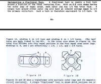
this is tempting, but seems like a coupling mess.
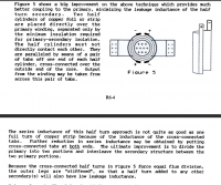
This is what i imagined a 1/2 turn primary to look like.
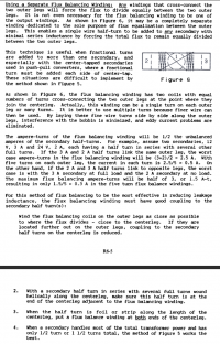
I have no idea how these "balance windings" should be wuond, they obviously cant be a short circuit. I think they must carry current to oppose the different volt potential?
Patrick, Fri Sept 19 2014, 07:27AM
Im needing others to review my math:
 possible MOSFET
Im operating with +100 Volts through one primary of 1.5 turns, then -100 volts through the other 1.5 turns. the primary is 3 total turns CT is positive.
so im not sure if the 1.5 turns is multiplied or divided ?
EDIT: the more i think (but am not sure) if the core supports 100v per turn then the 1.5 x 100 = 150 V input. so ill put 150 V in positive then 150 V in negative. I think.
So for the secondary, if its 200 turns x 100 V per Turns = 20,000v.
Which means:
-100v in = -20kv.
+100v in = +20kv.
I do have questions about "low-turn-count" primaries. can a 1/2 tun be used? or do they have to be integers?

this is tempting, but seems like a coupling mess.

This is what i imagined a 1/2 turn primary to look like.

I have no idea how these "balance windings" should be wuond, they obviously cant be a short circuit. I think they must carry current to oppose the different volt potential?
Re: High Voltage Planar Ferrite transformers. ( Intial Experiments )
Tony Matt, Fri Sept 19 2014, 11:44PM
Hi Patric,
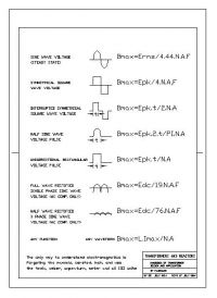
Here a summary of the equations that allows you calculate the Bmax in any core .
Regards
Tony Matt, Fri Sept 19 2014, 11:44PM
Hi Patric,
Here a summary of the equations that allows you calculate the Bmax in any core .
Regards

Re: High Voltage Planar Ferrite transformers. ( Intial Experiments )
Patrick, Sat Sept 20 2014, 12:01AM
But do i calculate +Bmax then -Bmax as the transformer has a center tap which swings 2 times Bsat...
so i think this is why there is a 2 in the denominator times the turns 'N'...
Patrick, Sat Sept 20 2014, 12:01AM
But do i calculate +Bmax then -Bmax as the transformer has a center tap which swings 2 times Bsat...
so i think this is why there is a 2 in the denominator times the turns 'N'...
Re: High Voltage Planar Ferrite transformers. ( Intial Experiments )
Hazmatt_(The Underdog), Sat Sept 20 2014, 03:06PM
100V per turn, is that reasonable?
How long is one turn, maybe 12", and you're wanting to see 100V across that? Maybe...Maybe open circuit operation would give you that kind of voltage output, but I don't think you're going to be anywhere near that in operation.
I'm designing a small transformer for a B+ application, and its more like 1V per turn loaded, probably close to 1.5V per turn unloaded.
10V per turn is probably more realistic, but I can't wait to see how it turns out, I hope it works!
Re: High Voltage Planar Ferrite transformers. ( Intial Experiments )
Patrick, Sat Sept 20 2014, 04:00PM
the more i think the more i believe its a 150 V input. for a 1.5 primary turn. then the flux density makes more sense.
Patrick, Sat Sept 20 2014, 04:00PM
Hazmatt_(The Underdog) wrote ...
100V per turn, is that reasonable?
the whole point is to try to get super high volts-per-turn, to avoid high turns on the secondary. If its even possible. for + and - 7kV, 14kV rms, that would mean 70t x 100, which is more wind-able for our purposes. 100V per turn, is that reasonable?
the more i think the more i believe its a 150 V input. for a 1.5 primary turn. then the flux density makes more sense.
Re: High Voltage Planar Ferrite transformers. ( Intial Experiments )
Ash Small, Sat Sept 20 2014, 09:19PM
103 VPT @ 100kHz sounds a bit high for ~5cm^2 ferrite to me but I'm only going on what I worked out for 18cm^2 ferrite @~30VPT @25kHz.
Do you have the formula that relates VPT to frequency?
Ash Small, Sat Sept 20 2014, 09:19PM
103 VPT @ 100kHz sounds a bit high for ~5cm^2 ferrite to me but I'm only going on what I worked out for 18cm^2 ferrite @~30VPT @25kHz.
Do you have the formula that relates VPT to frequency?
Re: High Voltage Planar Ferrite transformers. ( Intial Experiments )
Patrick, Sat Sept 20 2014, 11:45PM
Patrick, Sat Sept 20 2014, 11:45PM
Ash Small wrote ...
Do you have the formula that relates VPT to frequency?
do you mean a function that plots VPT vs Freq?Do you have the formula that relates VPT to frequency?
Re: High Voltage Planar Ferrite transformers. ( Intial Experiments )
Ash Small, Sun Sept 21 2014, 12:09AM
Yep. I assume it may be linear, but it's always best to check. It's a 'volt second' thing, isn't it?
Ash Small, Sun Sept 21 2014, 12:09AM
Patrick wrote ...
Ash Small wrote ...
Do you have the formula that relates VPT to frequency?
do you mean a function that plots VPT vs Freq?Do you have the formula that relates VPT to frequency?
Yep. I assume it may be linear, but it's always best to check. It's a 'volt second' thing, isn't it?
Re: High Voltage Planar Ferrite transformers. ( Intial Experiments )
Patrick, Sun Sept 21 2014, 01:10AM
yep my calc says its a linear function, and i see no exponents.
further, maybe i need a single pulse generating 555 timer which drives the power mosfet. then a secondary connected to a o-scope, suitably divieded.
i dont know if a 555 IC can drive a large gate mosfet and still generate a square pulse...
EDIT: i feel like im forgetting something.
Re: High Voltage Planar Ferrite transformers. ( Intial Experiments )
Uspring, Sun Sept 21 2014, 07:44AM
Vmax = 2*pi*f*Bmax*A
This is equivalent to the first equation in Tony Matts list. The factor of 4.4 there is different from 2*pi. That is due to the Vrms, that is used there instead of Vmax.
For the A, f and Bmax quoted that works out to be about 100V per turn. You should use units of m² for A and Tesla (V*s/m²) for B.
Usage of Tesla instead of Gauss is much more pc in this forum and note that 1 Tesla is equal to 10000 Gauss.
Inductance of a 1.5 turn primary will be low even considering the large effect of the ferrite, so primary reactive currents might be larger than the mosfets or the primary winding like even for an unloaded secondary.
Uspring, Sun Sept 21 2014, 07:44AM
Im needing others to review my math:Faradays law states, that the voltage per turn is equal to the rate of change of the magnetic flux going through the turn. The flux is B*A, so for a sinusoidal time dependence you get:
Vmax = 2*pi*f*Bmax*A
This is equivalent to the first equation in Tony Matts list. The factor of 4.4 there is different from 2*pi. That is due to the Vrms, that is used there instead of Vmax.
For the A, f and Bmax quoted that works out to be about 100V per turn. You should use units of m² for A and Tesla (V*s/m²) for B.
Usage of Tesla instead of Gauss is much more pc in this forum and note that 1 Tesla is equal to 10000 Gauss.

Inductance of a 1.5 turn primary will be low even considering the large effect of the ferrite, so primary reactive currents might be larger than the mosfets or the primary winding like even for an unloaded secondary.
Re: High Voltage Planar Ferrite transformers. ( Intial Experiments )
Sulaiman, Sun Sept 21 2014, 07:47AM
Here are a few sums; (I have to think in metric)
1) Volume of one ferrite piece = 2.5 cm3, one pair = 5 cm3
2) Surface area of one pair = 15.8 cm2
3) In air, a 50C rise in temperature would allow 1.73W core dissipation (dT=(mW/cm2)^,833)
4) 1730mW/5cm3 = 345 mW/cm3
5) at 100kHz 345mW/cm3 = 200 gauss from your data sheet = 20mT
6) cross-sectional core area = 1.1 cm2
7) flux = 0.02 x 0.00011 = 2.1875 uWb
8) volts/turn = 2 x pi x 100E3 x 2.1875E-6 = 1.3744 Vpk
So if my calculations are correct, in air you could have 1.37 Volts peak per turn at 100 kHz with a 50C temperature rise if the copper losses are small.
Notice saturation flux density is not used at all, it's core loss vs. flux density and frequency.
Since copper losses will not be negligible, I guess that for each core set (pair) you can have about 1 Vpeak per turn in air at 100 kHz.
So my guess is for three core pairs.... 3 V peak (2.1 Vrms) per turn in air at 100 kHz
I don't know how to calculate for oil, but I guess 5 Vrms/turn continuous duty.
Please report on what you can actually achieve in continuous duty.
EDIT: D-oh .. see next post ... 2000 gauss = 200mT so 30 Vpeak for three core pairs in air.
Re: High Voltage Planar Ferrite transformers. ( Intial Experiments )
Uspring, Sun Sept 21 2014, 08:26AM
Good point. All your calculations seem valid. But did you get the core loss right? In the field for 345mW/cm³ at 100kHz looks like 2000 Gauss.
Uspring, Sun Sept 21 2014, 08:26AM
Good point. All your calculations seem valid. But did you get the core loss right? In
 the field for 345mW/cm³ at 100kHz looks like 2000 Gauss.
Re: High Voltage Planar Ferrite transformers. ( Intial Experiments )
Dr. Slack, Sun Sept 21 2014, 08:29AM
I'm always nervous when people speak about fractions of a turn, like 1.5. It's topologically impossible to have exactly that, though it is possible to synthesise the effect with multiple windings and legged cores. It is certainly not possible to put 'half a turn' on with a single winding without getting something very undesirable.
How are your 1.5 turns arranged / intended to be arranged?
Re: High Voltage Planar Ferrite transformers. ( Intial Experiments )
Uspring, Sun Sept 21 2014, 09:17AM
Yeah, makes me queasy, too. In a sense half turns are impossible, since currents always flow in complete loops. It is possible to dump charges in e.g. a big aluminium ball, but that doesn't work for any length of time.
The term "self inductance" is motivated by the effect of current in one part of the wire on other parts of it. That is the cause of the inductance of a solenoid, where wires are closely spaced, to be proportional to n². The inductance of a single straight wire on the other hand is proportional to its length.
What constitutes a half turn depends on its spacing relative to the wires leading to it and also e.g. ferrites, which guide the magnetic field.
Re: High Voltage Planar Ferrite transformers. ( Intial Experiments )
Ash Small, Sun Sept 21 2014, 11:28AM
This was my 'gut feeling' when I first looked at this, based on what I remember of calculations for my own project. From the 'pulse generator' research I did for my electronic ignition project, higher VPT is possible, but only at much higher frequencies, but I'm very interested in how this project turns out.
I also have reservations about the 'half turn' thing.
EDIT: I've not got into too much detail with the maths here yet, partly because I think oil cooling is the way to go here.
Ash Small, Sun Sept 21 2014, 11:28AM
Sulaiman wrote ...
EDIT: D-oh .. see next post ... 2000 gauss = 200mT so 30 Vpeak for three core pairs in air.
EDIT: D-oh .. see next post ... 2000 gauss = 200mT so 30 Vpeak for three core pairs in air.
This was my 'gut feeling' when I first looked at this, based on what I remember of calculations for my own project. From the 'pulse generator' research I did for my electronic ignition project, higher VPT is possible, but only at much higher frequencies, but I'm very interested in how this project turns out.
I also have reservations about the 'half turn' thing.
EDIT: I've not got into too much detail with the maths here yet, partly because I think oil cooling is the way to go here.
Re: High Voltage Planar Ferrite transformers. ( Intial Experiments )
Conundrum, Sun Sept 21 2014, 02:28PM
Glycol?
Also there are many cheap solvents with low envirowhiner potential (ie ethanol) and despite being flammable when mixed with other materials are reasonable insulators and easy to use.
Conundrum, Sun Sept 21 2014, 02:28PM
Glycol?
Also there are many cheap solvents with low envirowhiner potential (ie ethanol) and despite being flammable when mixed with other materials are reasonable insulators and easy to use.
Re: High Voltage Planar Ferrite transformers. ( Intial Experiments )
Hazmatt_(The Underdog), Sun Sept 21 2014, 03:51PM
If it were me, I would stay away from anything soluable in water, because if it's soluable in water, it's also potentially capable of having dissolved salts in the water, increasing that conductivity to a failure point.
You're going for very high potentials, and it doesn't take much for corona to start, and then the end is near.
I'd go with oil or paraffin wax, but that's just me.
Re: High Voltage Planar Ferrite transformers. ( Intial Experiments )
Sulaiman, Sun Sept 21 2014, 04:58PM
Since power/weight and power/volume ratios seem important for this project
I'd consider potting the windings and clamping the core to a heat conductor/sink.
e.g. part of aircraft fuselage etc.
Sulaiman, Sun Sept 21 2014, 04:58PM
Since power/weight and power/volume ratios seem important for this project
I'd consider potting the windings and clamping the core to a heat conductor/sink.
e.g. part of aircraft fuselage etc.
Re: High Voltage Planar Ferrite transformers. ( Intial Experiments )
Patrick, Sun Sept 21 2014, 05:05PM
OKmm I guess I'll look a 1 turn. I'll definitely use oil.
I fail to see why I can't use 3500 to 3800 guass?
Patrick, Sun Sept 21 2014, 05:05PM
OKmm I guess I'll look a 1 turn. I'll definitely use oil.
I fail to see why I can't use 3500 to 3800 guass?
Re: High Voltage Planar Ferrite transformers. ( Intial Experiments )
Dr. Slack, Sun Sept 21 2014, 09:28PM
You can have the effect of 1.5 turns if you like, it's just that you'd need a core with two symmetric holes, and a total of 3 turns in 2 parallel windings.
Dr. Slack, Sun Sept 21 2014, 09:28PM
Patrick wrote ...
OKmm I guess I'll look at 1 turn.
OKmm I guess I'll look at 1 turn.
You can have the effect of 1.5 turns if you like, it's just that you'd need a core with two symmetric holes, and a total of 3 turns in 2 parallel windings.
Re: High Voltage Planar Ferrite transformers. ( Intial Experiments )
Patrick, Sun Sept 21 2014, 09:54PM
Patrick, Sun Sept 21 2014, 09:54PM
Dr. Slack wrote ...
You can have the effect of 1.5 turns if you like, it's just that you'd need a core with two symmetric holes, and a total of 3 turns in 2 parallel windings.
I fail to understand, can you diagram this? Patrick wrote ...
OKmm I guess I'll look at 1 turn.
OKmm I guess I'll look at 1 turn.
You can have the effect of 1.5 turns if you like, it's just that you'd need a core with two symmetric holes, and a total of 3 turns in 2 parallel windings.
Re: High Voltage Planar Ferrite transformers. ( Intial Experiments )
Dr. Slack, Sun Sept 21 2014, 10:12PM
Too late at night, can't be ar$ed to fire up something to draw it with. Is the specification of 'symmetric' not enough of a hint?
An E core has a fat central limb, and two skinny outer limbs, so two symmetric holes. Put one real turn round each limb, and figure out what their flux linkage is. Alternatively, figure out what the ampere turns is. Then you'll see how to put the two outer limb turns in parallel, with the correct phasing, to give you the effect of half a turn on the central limb. If you haven't got an E core, or a binocular core, then you can't do it.
Re: High Voltage Planar Ferrite transformers. ( Intial Experiments )
Ash Small, Sun Sept 21 2014, 11:32PM
I think you can, either with extra cooling, or with reduced load.........Losses will increase, though, what percentage efficiency are you after?
Ash Small, Sun Sept 21 2014, 11:32PM
Patrick wrote ...
I fail to see why I can't use 3500 to 3800 guass?
I fail to see why I can't use 3500 to 3800 guass?
I think you can, either with extra cooling, or with reduced load.........Losses will increase, though, what percentage efficiency are you after?
Re: High Voltage Planar Ferrite transformers. ( Intial Experiments )
Uspring, Mon Sept 22 2014, 11:34AM
You could get a symmetric primary by connecting the 3 turns at a short side of the winding and the center tap at the opposite side.
Uspring, Mon Sept 22 2014, 11:34AM
You could get a symmetric primary by connecting the 3 turns at a short side of the winding and the center tap at the opposite side.
Re: High Voltage Planar Ferrite transformers. ( Intial Experiments )
Sulaiman, Mon Sept 22 2014, 06:53PM
it would be unfortunate if you mess up on the turns thing,
I would rather use a higher/lower voltage/frequency than 'optimal'
and have an integer number of turns.
No need to over-stress a first prototype, (it will somehow over-stress itself)
get it working and go to Mk.2 ;)
Re: High Voltage Planar Ferrite transformers. ( Intial Experiments )
Patrick, Mon Sept 22 2014, 07:22PM
Im laying out a new board to etch, to test several primary configurations. it will have a current limited pulse generator with oscilloscope probe points.
Patrick, Mon Sept 22 2014, 07:22PM
Im laying out a new board to etch, to test several primary configurations. it will have a current limited pulse generator with oscilloscope probe points.
Re: High Voltage Planar Ferrite transformers. ( Intial Experiments )
Sulaiman, Mon Sept 22 2014, 07:55PM
As far as I know;
for r.f. the transformer could be considered as two ferrite chokes, physically parallel, wired in series
so it would be two half-turns in series per full/integer turn.
at sensible smps frequencies,
you certainly can use 1/2 in turns ratios BUT
one side has one half of a full turn less than the other, 100:99 is negligible
1:2 means 1/2 of one core has to operate at 1/2 'capacity' so that the other half is within limits
the reduced loss in one half allows a little more dissipation in the other,
but you always lose some.
for efficient transformer action (esp. insulation)
the method of using parallel windings on the outside legs as 1/2 ratio transformers
works well but may be harder to insulate and is a slightly less efficient use of copper I think,
and ... rfi will be worse ... UAV + RFI = not good
Side note; a brand of motor drive used a c6VA 'mains' transformer EI with the 'mains' wiring as sense and one turn current-sense wire .. ok
a higher output current version had a '1/2 turn' current sense wire, presumably assuming doubling the transformer ratio ... not entirely ... flux shunting.
Re: High Voltage Planar Ferrite transformers. ( Intial Experiments )
Patrick, Tue Sept 23 2014, 07:45AM
ill be starting the etch tomorrow. the test board will have several features and can be configured based on failures and successes. o-scope voltage diveders and triggers will also be used.
so ill try 1 turn first and see if we get the expected v/t out of the secondary.
Re: High Voltage Planar Ferrite transformers. ( Intial Experiments )
Dr. Slack, Tue Sept 23 2014, 07:55AM
Consider the following diagrams, they are the plan of an E core, showing the copper windings.
The top one is obviously a full turn, though you could consider each pass through a winding window as half a turn, which are then connected in series, to make a full turn.
The middle one is also two half turns in series. Follow the current path and you'll see the effect in the centre limb, Ampere.turns or volts.seconds, is exactly the same as the first diagram. The effect in the outer limbs is exactly the same as well. The same that is, if we assume the core has infinite permeability, and air has zero. That's a good first order approximation, but to the extent that it's only approximate, the second diagram does have a higher leakage inductance than the first to a coil wound on the central core.
The last one takes the two half turns and puts them in parallel. They now have half the voltage and twice the current at the terminals, so they are behaving like half a turn on the centre limb.
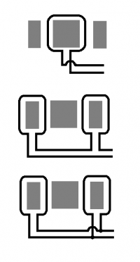
You may wonder why the top diagram has a crossover. It's because I drew the middle one first, and wanted to keep the terminal polarity consistent in all three, there's enough confusion to be had without adding to it unnecessarily.
Now if you use only one of these half turn coils, which is what most people talking about half a turn do, its leakage inductance to a coil on the central limb is huge, even if the core permeability is infinite.
Dr. Slack, Tue Sept 23 2014, 07:55AM
Consider the following diagrams, they are the plan of an E core, showing the copper windings.
The top one is obviously a full turn, though you could consider each pass through a winding window as half a turn, which are then connected in series, to make a full turn.
The middle one is also two half turns in series. Follow the current path and you'll see the effect in the centre limb, Ampere.turns or volts.seconds, is exactly the same as the first diagram. The effect in the outer limbs is exactly the same as well. The same that is, if we assume the core has infinite permeability, and air has zero. That's a good first order approximation, but to the extent that it's only approximate, the second diagram does have a higher leakage inductance than the first to a coil wound on the central core.
The last one takes the two half turns and puts them in parallel. They now have half the voltage and twice the current at the terminals, so they are behaving like half a turn on the centre limb.

You may wonder why the top diagram has a crossover. It's because I drew the middle one first, and wanted to keep the terminal polarity consistent in all three, there's enough confusion to be had without adding to it unnecessarily.
Now if you use only one of these half turn coils, which is what most people talking about half a turn do, its leakage inductance to a coil on the central limb is huge, even if the core permeability is infinite.
Re: High Voltage Planar Ferrite transformers. ( Intial Experiments )
Patrick, Tue Sept 23 2014, 08:09AM
ok that graphic helps, we'll able to test and see different schemes shortly. I have several ideas id like to demonstrate.
Patrick, Tue Sept 23 2014, 08:09AM
ok that graphic helps, we'll able to test and see different schemes shortly. I have several ideas id like to demonstrate.
Re: High Voltage Planar Ferrite transformers. ( Intial Experiments )
Uspring, Tue Sept 23 2014, 10:51AM
Dr. Slack wrote:
That would imply a coupling of 1/3 between the outer coils, which means a total inductance of the series circuit to be 8/3 ( =2*(1+k) ) of a single side. For a parallel circuit I get a factor of 2/3 ( =0.5*(1+k) ) compared to a single side loop.
The center loop (top diagram) would have twice the inductance of a side loop due to the doubling of loop area.
Transformation ratios would also be somewhat different from the upper diagram.
Uspring, Tue Sept 23 2014, 10:51AM
Dr. Slack wrote:
The middle one is also two half turns in series. Follow the current path and you'll see the effect in the centre limb, Ampere.turns or volts.seconds, is exactly the same as the first diagram.I'm trying to understand this. Assuming that the center ferrite cross section is twice that of each outer limb, wouldn't the flux from one side coil split up as 2/3 going through the center and 1/3 going through the other limb?
That would imply a coupling of 1/3 between the outer coils, which means a total inductance of the series circuit to be 8/3 ( =2*(1+k) ) of a single side. For a parallel circuit I get a factor of 2/3 ( =0.5*(1+k) ) compared to a single side loop.
The center loop (top diagram) would have twice the inductance of a side loop due to the doubling of loop area.
Transformation ratios would also be somewhat different from the upper diagram.
Re: High Voltage Planar Ferrite transformers. ( Intial Experiments )
Dr. Slack, Tue Sept 23 2014, 12:03PM
No, the top two diagrams have exactly the same inductance, and the lowest one 1/4 the inductance of the others because of the different electrical connection. Starting from the symmetry of the situation is the easiest way to figure it out. In the middle diagram, the two outer limbs have the same current wrapped round them, each producing the same H field at the centre limb. They add together. Same H field for each, same area, same length, so same B field.
In the bottom diagram, the voltages of the two half turns are constrained by the connection to be equal. This means the integrated volt.seconds in the two limbs are equal, again an equal split of the central flux to the outers.
It's an interesting question of why the two half coils are not coupled, as they are wound on bits of the same core. The important point is the symmetry. A magnetic wall exists down the middle of the central leg. You could bisect the central leg into two half areas without changing the performance of the system at all. No lines of flux cross this mid-line, so it wouldn't 'see' the difference. Having got this zero flux magnetic wall, you can of course now physically seperate the two halves, again without any change to the performance, like here, where you can use a pair of C cores instead of E cores
You will notice there is no metal between the two sets of C cores, any contact is only incidental. That's because when they are symmetrical, no flux crosses the mid-line.
Now it's possible to understand the difference between using one 'half turn' which wrecks leakage inductance, and two 'half turns' in parallel, which maintain symmetry. Think of it as each outer limb's half turn 'energising' half of the central limb. If you put what you think is a half turn around one outer limb, then what you actually have is a full turn around half of the total transformer core, a very different animal.
A quick way to demonstrate that the first two diagrams give the same inductance is to notice that they are in fact topologically *identical*. Short the input terminals to make a loop of wire. Now continuously deform the loop of the second diagram until it can lie on top of the loop of the first diagram. Note that this is a 2D diagram of a 3D situation, we are not in flatland. The only thing that the Amps and Teslas care about is the topology, how many times a wire threads through what hole in the core, not the big or small, left or right route the wire takes when it's outside the core. You will need to take a wire over the complete core as part of that movement.
Dr. Slack, Tue Sept 23 2014, 12:03PM
Uspring wrote ...
Dr. Slack wrote:
That would imply a coupling of 1/3 between the outer coils, which means a total inductance of the series circuit to be 8/3 ( =2*(1+k) ) of a single side. For a parallel circuit I get a factor of 2/3 ( =0.5*(1+k) ) compared to a single side loop.
The center loop (top diagram) would have twice the inductance of a side loop due to the doubling of loop area.
Transformation ratios would also be somewhat different from the upper diagram.
Dr. Slack wrote:
The middle one is also two half turns in series. Follow the current path and you'll see the effect in the centre limb, Ampere.turns or volts.seconds, is exactly the same as the first diagram.I'm trying to understand this. Assuming that the center ferrite cross section is twice that of each outer limb, wouldn't the flux from one side coil split up as 2/3 going through the center and 1/3 going through the other limb?
That would imply a coupling of 1/3 between the outer coils, which means a total inductance of the series circuit to be 8/3 ( =2*(1+k) ) of a single side. For a parallel circuit I get a factor of 2/3 ( =0.5*(1+k) ) compared to a single side loop.
The center loop (top diagram) would have twice the inductance of a side loop due to the doubling of loop area.
Transformation ratios would also be somewhat different from the upper diagram.
No, the top two diagrams have exactly the same inductance, and the lowest one 1/4 the inductance of the others because of the different electrical connection. Starting from the symmetry of the situation is the easiest way to figure it out. In the middle diagram, the two outer limbs have the same current wrapped round them, each producing the same H field at the centre limb. They add together. Same H field for each, same area, same length, so same B field.
In the bottom diagram, the voltages of the two half turns are constrained by the connection to be equal. This means the integrated volt.seconds in the two limbs are equal, again an equal split of the central flux to the outers.
It's an interesting question of why the two half coils are not coupled, as they are wound on bits of the same core. The important point is the symmetry. A magnetic wall exists down the middle of the central leg. You could bisect the central leg into two half areas without changing the performance of the system at all. No lines of flux cross this mid-line, so it wouldn't 'see' the difference. Having got this zero flux magnetic wall, you can of course now physically seperate the two halves, again without any change to the performance, like here, where you can use a pair of C cores instead of E cores

You will notice there is no metal between the two sets of C cores, any contact is only incidental. That's because when they are symmetrical, no flux crosses the mid-line.
Now it's possible to understand the difference between using one 'half turn' which wrecks leakage inductance, and two 'half turns' in parallel, which maintain symmetry. Think of it as each outer limb's half turn 'energising' half of the central limb. If you put what you think is a half turn around one outer limb, then what you actually have is a full turn around half of the total transformer core, a very different animal.
A quick way to demonstrate that the first two diagrams give the same inductance is to notice that they are in fact topologically *identical*. Short the input terminals to make a loop of wire. Now continuously deform the loop of the second diagram until it can lie on top of the loop of the first diagram. Note that this is a 2D diagram of a 3D situation, we are not in flatland. The only thing that the Amps and Teslas care about is the topology, how many times a wire threads through what hole in the core, not the big or small, left or right route the wire takes when it's outside the core. You will need to take a wire over the complete core as part of that movement.
Re: High Voltage Planar Ferrite transformers. ( Intial Experiments )
Uspring, Tue Sept 23 2014, 02:04PM
Dr. Slack wrote:
But think of another experiment: Gradually reduce the center cross section in the middle diagram until it finally disappears. Then you'll have two windings in series but oppositely wound. The resulting inductance would be zero. But also the symmetry argument would hold up to the point the center section gets infintely thin. Any idea about this?
I made an error in the calculation in my previous post. Since the flux is inverted from one side to the other the coupling should be k=-1/3.
Uspring, Tue Sept 23 2014, 02:04PM
Dr. Slack wrote:
A magnetic wall exists down the middle of the central leg. You could bisect the central leg into two half areas without changing the performance of the system at all. No lines of flux cross this mid-line, so it wouldn't 'see' the difference.The symmetry argument is compelling and thinking of it I had the same idea of bisection before I read your remark.
But think of another experiment: Gradually reduce the center cross section in the middle diagram until it finally disappears. Then you'll have two windings in series but oppositely wound. The resulting inductance would be zero. But also the symmetry argument would hold up to the point the center section gets infintely thin. Any idea about this?
I made an error in the calculation in my previous post. Since the flux is inverted from one side to the other the coupling should be k=-1/3.
Re: High Voltage Planar Ferrite transformers. ( Intial Experiments )
Dr. Slack, Tue Sept 23 2014, 03:54PM
Hmm, I'm not sure you understand the concept of 'turns' here, or I don't understand what you're proposing. If you thin the core down until it vanishes, then you don't have turns either, just a wiggly bit of wire in fresh air.
If you stop the thinning process just before it vanishes, then the first order approximation of the core flux totally dominating the air flux is broken, and the paths of all the wires matters, not just those threading the core. Whether the thin-core flux is small, infinitessimal or zero compared to the air flux, when you add the fields from either just the 'half turns', or all the wires in the second diagram, I don't see the inductance vanishing in either case. What are you seeing?
You do sometimes see air-cored RF chokes and transformers described as having (for instance) 3.5 turns. Their geometry is a spring with 3.5 turns, and then a straight piece of wire down to complete the circuit. But is it one wiggly turn, or 4 turns of different geometry? Because it's all in air, it doesn't matter. Just do Biot Savart and calculate the inductance, Maxwell and his equations don't care what words you choose to use to describe it. An inductor with that geometry will indeed have more L than a '3 turn' inductor, and less than a '4 turn'. But those are geometric shape turns, not Maxwell topology flux linkage turns.
Did you try yet to see that the first and second diagrams are topologically equivalent, and so have exactly the same inductance?
Re: High Voltage Planar Ferrite transformers. ( Intial Experiments )
Tony Matt, Wed Sept 24 2014, 01:38AM
Hi !
I'd sugest leave the fractional turns at side, and try to find the number of turns that Patric is looking for.
I have tested trafos with fractional turns, allways given bad side effects as high dispertion inductance and high voltage regulation.
Tony Matt, Wed Sept 24 2014, 01:38AM
Hi !
I'd sugest leave the fractional turns at side, and try to find the number of turns that Patric is looking for.
I have tested trafos with fractional turns, allways given bad side effects as high dispertion inductance and high voltage regulation.
Re: High Voltage Planar Ferrite transformers. ( Intial Experiments )
Dr. Slack, Wed Sept 24 2014, 06:04AM
Yes, fractional turns has not been as much a thread hijack as a thread derailment. Sorry for my contribution to that. I wonder if the mods can excise the relevant posts and transplant them to your new thread on the topic.
Dr. Slack, Wed Sept 24 2014, 06:04AM
Yes, fractional turns has not been as much a thread hijack as a thread derailment. Sorry for my contribution to that. I wonder if the mods can excise the relevant posts and transplant them to your new thread on the topic.
Re: High Voltage Planar Ferrite transformers. ( Intial Experiments )
Patrick, Wed Sept 24 2014, 06:16AM
the whole idea from the beginning of this thread involved fractional turns, so I need all the comments I can get. Test board is nearing completion.
Patrick, Wed Sept 24 2014, 06:16AM
the whole idea from the beginning of this thread involved fractional turns, so I need all the comments I can get. Test board is nearing completion.
Re: High Voltage Planar Ferrite transformers. ( Intial Experiments )
Uspring, Wed Sept 24 2014, 06:54AM
Thank you Patrick since I want to make another comment to what Dr. Slack said.
We have a left-right mirror symmetry when looking at your drawings. That implies, that the field also has this symmetry and that suggests, that you can treat the left and right part separately, since no field lines from the left turn go through the right turn and vice versa.
The picture of field lines in the symmetric case is deviously misleading.
Uspring, Wed Sept 24 2014, 06:54AM
Thank you Patrick since I want to make another comment to what Dr. Slack said.
Hmm, I'm not sure you understand the concept of 'turns' here, or I don't understand what you're proposing. If you thin the core down until it vanishes, then you don't have turns either, just a wiggly bit of wire in fresh air.Maybe I misunderstood how your drawing was meant. I thought of 2 E shaped cores put face to face to form an 8. The drawing is in the plane where the cores meet. I was also disregarding the secondary turns for the time being, so there are no wires in air, when you thin out the central leg.
We have a left-right mirror symmetry when looking at your drawings. That implies, that the field also has this symmetry and that suggests, that you can treat the left and right part separately, since no field lines from the left turn go through the right turn and vice versa.
It's an interesting question of why the two half coils are not coupled, as they are wound on bits of the same core. The important point is the symmetry. A magnetic wall exists down the middle of the central leg. You could bisect the central leg into two half areas without changing the performance of the system at allIf you apply voltage to only one limb, the symmetry is broken and there will be field lines coming from the driven limb and going to the other one, inducing a voltage there. So the 2 limbs _are_ coupled and that means, that you cannot just add up the separate limb inductances to get the series inductance.
The picture of field lines in the symmetric case is deviously misleading.
Re: High Voltage Planar Ferrite transformers. ( Intial Experiments )
Dr. Slack, Wed Sept 24 2014, 08:38AM
Hmm. Lots of things, and unfortunately many of them will sound a bit like avoiding the question. I had assumed a model, which is correct in the limit of infinite core permeability, and/or zero vacuum permeability, ie it's just turns counting and topology, and a constant cross section core. Real life will deviate from that, but by percent. The important thing with transformers is first to get something that can work even theoretically in that perfect limit, like the policy of balancing the two half turns, and then optimising it practically, like twisting the lead-in wires together, and striving to make the outer limbs physically the same length and area.
Now many of your thought experiments break that model. So we are left confusing theoretical possibility, and practical optimisation.
I think I now understand that you were thinning the central limb only, essentially leaving a ring core, with the two outer windings phased in opposition. In the limit of zero vacuum permeability, that does indeed have zero inductance. But it's not a transformer to windings on a central limb, so whatever inductance a not-transformer has, it isn't really relevant to the discussion. In real life, a small flux occurs through the air/vacuum between the top and bottom, so there is a very small inductance. This was the non-zero inductance I was referring to when I thought you were removing the entire core. The inductance of the opposed ring-core will be more or less twice than the zero core case, as half of the length of the magnetic circuit is 'shorted out' by the core.
While Patrick still wants to pursue half turns, I think the geometry he has chosen for the cores and formers could make it tricky in practice to achieve a turn on the centre and two balanced outer turns for an effective half turn. Unless of course the former shown is only used to support the secondary, and the primary uses discrete wire wound onto the cores, I don't see room for a primary former.
While I am sympathetic to your looking for the coupling between the two coils, remember that they are *only ever used* in series or parallel, not independently. The two outer limb coils used independently will have finite coupling, but when they are forced, by terminal connection, to operate together, the core central limb can be split by a magnetic wall and the coupling vanishes. Now I can't be bothered to do all the linear superposition stuff, or calculating the inductance in detail as the other coil is shorted and open. There are some things that you have to do in detail, and some you don't. For instance if a complicated system of rotating machinery appears to be producing net power, you don't have to delve into all the detail, you know from conservation of energy that it just can't. Similarly, my first and second diagrams have the same topology, so in the perfect limit of infinite core/vacuum permeability ratio they must have the same inductance. Period.
I thought the original task was 'how can Patrick implement half a turn properly?'. Balancing the outer limb turns achieves that. Leaving them unbalanced causes the horrible leakage inductance problems that burn people who attempt it without maintaining the symmetry. Now you don't really need to figure out what bad happens in detail. If you want to make a 4:1 transformer on a core, you wind 4 turns and one turn. That takes care of the topology, then you try to sort out the insulation, and leakage inductance, and all the other tricky practical optimisations. You don't wind 3 turns and then anguish that it's not 4, or start thinning the central leg down and wondering where your inductance went. Similarly if you want 0.5 turn, you put balanced turns in parallel round the outer limbs, and that takes care of the topology. Then worry about insulation and leakage inductance and heat removal and stray capacitance and all the other non-topology stuff that you have to.
I'm not going to contribute to this thread further, unless I can be bothered to crank up POVRAY, and make an animation showing that my first and second diagrams do indeed have the same topology. Or maybe I'll draw a few intermediate 2D diagrams to show it, but not as convincingly. I do urge you to look at those two diagrams, move one of the lead-in wires over the core (as you are allowed to do in a 3D situation), lengthen and shorten the wires (which doesn't change the topology) and see that they are indeed the same diagram.
I'm reminded of the man who went to the doctor, complaining that whenever he poked himself in the eye, it hurt. The doctor advised him to stop poking himself in the eye. But why does it hurt doctor? The details of why it hurts to self eye-poke don't really matter, stop poking yourself in the eye and all will be OK. An E core transformer with integer turns is balanced with respect to the outer limbs. If you put half a turn round one outer limb, poking its balance in the eye so to speak, resulting in different turns ratios on different parts of the transformer, it hurts. Keep it balanced by putting a turn on the outer limb, connected in parallel. Balanced restored. Eye stops hurting.
Re: High Voltage Planar Ferrite transformers. ( Intial Experiments )
Ash Small, Wed Sept 24 2014, 11:04AM
I'd forget the fractional turns thing for now, and run some tests with integer turns, in order to get some idea of what's practical and achievable
Ash Small, Wed Sept 24 2014, 11:04AM
Patrick wrote ...
the whole idea from the beginning of this thread involved fractional turns, so I need all the comments I can get. Test board is nearing completion.
the whole idea from the beginning of this thread involved fractional turns, so I need all the comments I can get. Test board is nearing completion.
I'd forget the fractional turns thing for now, and run some tests with integer turns, in order to get some idea of what's practical and achievable

Re: High Voltage Planar Ferrite transformers. ( Intial Experiments )
Uspring, Wed Sept 24 2014, 11:12AM
If you accept, that there is coupling, it will have changed by moving the turns, making the top and middle circuits different. That depends on my assumption, that the coupling of the outer limbs in the middle diagram is less than 1. Its topological variant has k=1.
Uspring, Wed Sept 24 2014, 11:12AM
The two outer limb coils used independently will have finite coupling, but when they are forced, by terminal connection, to operate together, the core central limb can be split by a magnetic wall and the coupling vanishes.Coupling doesn't depend on how you drive the coils. It depends solely on the geometry.
Similarly, my first and second diagrams have the same topology, so in the perfect limit of infinite core/vacuum permeability ratio they must have the same inductance. Period.I believe that the topological transformation you have in mind for the middle diagram is cutting through the central leg and joining the limbs so that the turns are adjacent. That looks indeed equivalent to the top diagram.
If you accept, that there is coupling, it will have changed by moving the turns, making the top and middle circuits different. That depends on my assumption, that the coupling of the outer limbs in the middle diagram is less than 1. Its topological variant has k=1.
Re: High Voltage Planar Ferrite transformers. ( Intial Experiments )
Dr. Slack, Wed Sept 24 2014, 12:22PM
No, the transformation I had in mind I said is specifically not cutting through the middle leg, but lifting the wire over the entire core. Imagine you are holding a cored inductor in one hand, and the pair of wires going to it in the other. Turn the core over so a different face is towards the wires. That's the extent of the transformation needed.
Anyhows, a much better way of looking at magnetically the same solution. This is much closer to a practical winding scheme for Patrick, as I've just remembered that he is in fact using multiple cores. Instead of splitting the central limb magnetically in half by considering each outer limb separately, let's split the centre limb in half by making it from two cores side by side. Magnetically, this is exactly the same situation, but it is probably easier for unbelievers to see that it works.
Now unfortunately, Patrick's OP shows 3 cores. This means that he could implement 1.33 or 1.67 turns by this scheme with trifilar wire. But for simplicity, let's stay with half turns as the diagram is easier. The extension to third turns with 3 cores or Nth turns with N cores is trivial.
The diagram below is for 1.5 turns effective wound on two cores, or an even number of cores, side by side. It is wound from bifilar wire, which avoids joints inside the transformer, or excess wire to get the joints outside, probably a good thing. To make it easier to see what's going on, I have made the two strands different colours.
Consider 2A entering the inductor. It splits as 1A into each wire. Look carefully at each core and count the magnetising ampere turns round it. 3 turns round each core, that's 3At for 2A input, 1.5 turns effective. The only place you may have trouble counting is on the left, where the wires go off to the supply. Don't forget that they join through the supply, so constitute two more Amps, making a total of 3At on the left as well.
Now consider the voltage generated by changing B field in the cores. The parts of the winding that go round one half core generate only half the voltage of the turns that go round both halves. So they act like half a turn. They are in parallel, so the two parts stay balanced.
Notice in the gap between the two cores, there are two more bits of wire, but they carry current in opposite directions, so generate no net H field. This is the only excess wire penalty that this arrangement suffers. In trying to make an efficient transformer, you really want as much of your wire doing electromagnetic work, and as little as possible just getting from A to B, as it's all causing IR drops. These two wires in the middle are the only cost of doing half turns this way. Using the outer limbs for half turns would be much more expensive in terms of IR drops, and leakage inductance for that matter, than this multiple core approach.
Now I've got the two half turns on physically distinct cores, explain where this coupling between the two half turns is coming from. That's why I said it's an interesting question. In the outer limb arrangement, when the 'half turns' are used independently, there is coupling. When *used strictly in parallel* there isn't, the magnetic wall is maintained in the core central leg by the electrical parallelism, so there is not the effect of coupling, whether or not it looks like there is coupling. This is magnetically and electrically equaivalent when used in the same balanced way, but now there is obviously no coupling if used unbalanced. An interesting conundrum, I don't understand why I don't understand it yet, but then I don't understand relativity or QM either.
But it needn't matter to Patrick, as this is a practical scheme that will work, even if we don't agree on why the equivalent scheme works.
<edit>
Whoa, stop press, it's even easier than that with multiple cores. Put three turns round one core with one wire. Put three turns round the second core with another wire. Put these two primaries in parallel. Stack the two cores side by side and wind the secondaries round both cores. I'll let you do the math.
This results in slightly more wasted wire than the diagram above, as there are now three cancelling wires going up/down the middle gap. But it affords a much nicer mechanical winding arrangement, and a simpler less head-scratching way of seeing that it also works.
</edit>
Re: High Voltage Planar Ferrite transformers. ( Intial Experiments )
Patrick, Thu Sept 25 2014, 09:57PM
ive finalized everything and am ready for the toner transfer to board.
but a problem has popped up. previously this printer worked fine, about 8 months ago. and its only used for PCB making.
Having gotten it all plugged in and ready to go it prints like this:
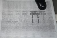
This smearing wont go away...
it should print like this:
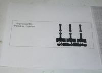

And this is the printer, brother 2170W.
i just cant figure out why it wont work after ive done everything i can think of to clean it. I dont know if the photo-drum is bad.
Patrick, Thu Sept 25 2014, 09:57PM
ive finalized everything and am ready for the toner transfer to board.
but a problem has popped up. previously this printer worked fine, about 8 months ago. and its only used for PCB making.
Having gotten it all plugged in and ready to go it prints like this:

This smearing wont go away...
it should print like this:


And this is the printer, brother 2170W.
i just cant figure out why it wont work after ive done everything i can think of to clean it. I dont know if the photo-drum is bad.
Re: High Voltage Planar Ferrite transformers. ( Intial Experiments )
Shrad, Fri Sept 26 2014, 08:12AM
charge leftover on the drum? have you cleaned it with something like methanol or isopropyl?
Shrad, Fri Sept 26 2014, 08:12AM
charge leftover on the drum? have you cleaned it with something like methanol or isopropyl?
Re: High Voltage Planar Ferrite transformers. ( Intial Experiments )
Patrick, Fri Sept 26 2014, 10:07AM
so, at 11$ ill try a new photo-drum, or buy a whole new printer just for PCBs at 110$.
Patrick, Fri Sept 26 2014, 10:07AM
Shrad wrote ...
charge leftover on the drum? have you cleaned it with something like methanol or isopropyl?
yep the pattern changed but it still smears the whole page. Having cleaned it, it was rolled with a uniform layer of powder, then after another bad print i looked, and the spots and sploches of toner where random on the photo-drum, and looked like the invert of the garbage page.charge leftover on the drum? have you cleaned it with something like methanol or isopropyl?
so, at 11$ ill try a new photo-drum, or buy a whole new printer just for PCBs at 110$.
Re: High Voltage Planar Ferrite transformers. ( Intial Experiments )
Patrick, Sun Sept 28 2014, 10:40PM
Sorry, for the lack of updates. But not being able to print a usuable transfer on Brother printers. With out a circuit bard i cant test differnt configurations.
Patrick, Sun Sept 28 2014, 10:40PM
Sorry, for the lack of updates. But not being able to print a usuable transfer on Brother printers. With out a circuit bard i cant test differnt configurations.
Re: High Voltage Planar Ferrite transformers. ( Intial Experiments )
Patrick, Tue Sept 30 2014, 05:06AM
trying for a good transfer, double sided insertion mount board.
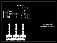

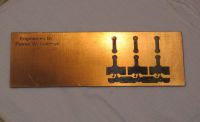
Crap transfer
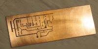
i dont think im getting it hot enough.
At this point im wondering if i should just print with a 3D printer, a single layer mask?
Patrick, Tue Sept 30 2014, 05:06AM
trying for a good transfer, double sided insertion mount board.


Crap transfer

i dont think im getting it hot enough.
At this point im wondering if i should just print with a 3D printer, a single layer mask?
Re: High Voltage Planar Ferrite transformers. ( Intial Experiments )
Patrick, Wed Oct 01 2014, 01:44AM
Circuit board ready to be drilled and populated.
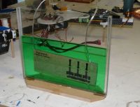
Start of etching.
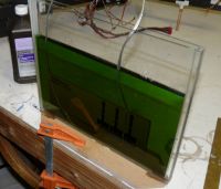
it got real dark quickly, then I think the etch slowed greatly.
I decided to clamp it to the table, as it seemed prudent.
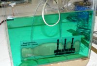
I added H2O2, enough to get it light again.
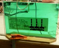
2 oZ copper, double sided board.

b

v
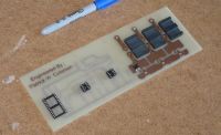
u

p
Patrick, Wed Oct 01 2014, 01:44AM
Circuit board ready to be drilled and populated.

Start of etching.

it got real dark quickly, then I think the etch slowed greatly.
I decided to clamp it to the table, as it seemed prudent.

I added H2O2, enough to get it light again.

2 oZ copper, double sided board.

b

v

u

p
Re: High Voltage Planar Ferrite transformers. ( Intial Experiments )
Electra, Wed Oct 01 2014, 10:21PM
Patrick good to see it progressing, don't think I was expecting to see so small mosfets. Out of curiosity what devices are they?
Trouble is I'm too set in my ways, to me I still think lots of power needs to be huge heatsinks with rows of big mosfets, and a few gigantic capacitors for reassurance. I can see now if you need it very light and small, conventional won't cut it.
Re: High Voltage Planar Ferrite transformers. ( Intial Experiments )
Patrick, Wed Oct 01 2014, 10:36PM
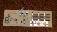
Semi's are:
-555 monostable timer
-Basic Stamp 2
-FAN7382 half bridge driver
-MOSFET = NTD4857NT4G ( 25 V, 78 A, 0.0057 Ohms )
-MOSFET = SUD50N03 ( 30 V, 50 A, 0.0095 Ohms )
-5 and 12 voltage regulators
Wire:
Polyester/Polyamideimide NEMA MW 35 C (32 awg ?)
ill use one or the other MOSFET not both, obviously. If i remember the contiuous current limit of the D0-252 case is 50 Amps. so 11 to 20 V input at 5 to 25 amps, mostly i think.
This board was only intended for 20 to 8 uS pulses every 1 to 3 seconds, unipolar. Its a experimental board to evaluate the transformer cores and windings. to see what work and doesnt with and a primary waveform and a secondary waveform being measured.
( 50khz to 125kHz is the goal )
EDIT: newest pic
Patrick, Wed Oct 01 2014, 10:36PM
Electra wrote ...
Patrick good to see it progressing, don't think I was expecting to see so small mosfets. Out of curiosity what devices are they?
Trouble is I'm too set in my ways, to me I still think lots of power needs to be huge heatsinks with rows of big mosfets, and a few gigantic capacitors for reassurance. I can see now if you need it very light and small, conventional won't cut it.
Semi's are:
-555 monostable timer
-Basic Stamp 2
-FAN7382 half bridge driver
-MOSFET = NTD4857NT4G ( 25 V, 78 A, 0.0057 Ohms )
-MOSFET = SUD50N03 ( 30 V, 50 A, 0.0095 Ohms )
-5 and 12 voltage regulators
Wire:
Polyester/Polyamideimide NEMA MW 35 C (32 awg ?)
ill use one or the other MOSFET not both, obviously. If i remember the contiuous current limit of the D0-252 case is 50 Amps. so 11 to 20 V input at 5 to 25 amps, mostly i think.
This board was only intended for 20 to 8 uS pulses every 1 to 3 seconds, unipolar. Its a experimental board to evaluate the transformer cores and windings. to see what work and doesnt with and a primary waveform and a secondary waveform being measured.
( 50khz to 125kHz is the goal )
EDIT: newest pic

Re: High Voltage Planar Ferrite transformers. ( Intial Experiments )
Dr. Slack, Fri Oct 03 2014, 04:19PM
Patrick
Do I take it from the way the board looks that each MOSFET drives a primary on a single core? If so, this means you will already implementing effectively 1/3rd primary turns correctly if you drive the MOSFETs in parallel.
Now if the primary drives are separate, instead of being a single wire drive, this means that balance between the cores is *not* required for operation, though it may or may not be obvious that it will be most efficient to balance them. Although the MOSFETs might be driven in parallel, by the magic of magnetics, they appear in series at the secondary terminal, as each is contributing X amount of change of flux linkage per second coupling into the secondary. If the primaries are unbalanced, the turns ratio at each core will be different, and simply different currents will be drawn from each primary to balance the cores. But for this to work, they must all be driven at the same time.
Re: High Voltage Planar Ferrite transformers. ( Intial Experiments )
Patrick, Fri Oct 03 2014, 08:27PM
yep i was hoping someone would see that. I hope im not crazy for thinking a full 1 turn around each core equates to 0.33 turns total. then with 300 secondary turns around all 3 cores, that means a 1:900 ratio or so. next at 25 V/t, 900t x 25 = 22.5 kV or there abouts.
Im wondering how much quadruple insulated 35 awg wire costs.
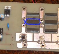
the blue line is how im running the primary wire.
the input could be 10-20 or so volts at 200 amps then 20 or 30 kV out, all in a single ferrite SMPS step.
After everyone advised me on the difficulty in fractional turns, i was really wanting to go back and think on flux lines them selves changing. I had this idea of multiple primaries in parallel, a secondary in series for quite a while. At least 6 years, the TI / Unitrode articles that made me think on the simple life of a flux line.
so right now im trying to get the 555 monostable to trigger but it wont.
Patrick, Fri Oct 03 2014, 08:27PM
yep i was hoping someone would see that. I hope im not crazy for thinking a full 1 turn around each core equates to 0.33 turns total. then with 300 secondary turns around all 3 cores, that means a 1:900 ratio or so. next at 25 V/t, 900t x 25 = 22.5 kV or there abouts.
Im wondering how much quadruple insulated 35 awg wire costs.

the blue line is how im running the primary wire.
the input could be 10-20 or so volts at 200 amps then 20 or 30 kV out, all in a single ferrite SMPS step.
After everyone advised me on the difficulty in fractional turns, i was really wanting to go back and think on flux lines them selves changing. I had this idea of multiple primaries in parallel, a secondary in series for quite a while. At least 6 years, the TI / Unitrode articles that made me think on the simple life of a flux line.
so right now im trying to get the 555 monostable to trigger but it wont.
Re: High Voltage Planar Ferrite transformers. ( Intial Experiments )
Ash Small, Fri Oct 03 2014, 09:30PM
This is the same topology I came up with in my electronic ignition thread, based on pulse generator theory, but mine uses flyback topology to generate ~50kV.
Ash Small, Fri Oct 03 2014, 09:30PM
Patrick wrote ...
I had this idea of multiple primaries in parallel, a secondary in series for quite a while.
I had this idea of multiple primaries in parallel, a secondary in series for quite a while.
This is the same topology I came up with in my electronic ignition thread, based on pulse generator theory, but mine uses flyback topology to generate ~50kV.
Re: High Voltage Planar Ferrite transformers. ( Intial Experiments )
Patrick, Fri Oct 03 2014, 09:35PM
did you series the flyback secondaries? i think youll be stuck after two. Ive done bipolar iggies and flybacks but it seems limited to two devices.
As for Dr. Sparks comment on driving at the sametime, ive got really fast MOSFETs being driven by a gate driver, and at 100kHz (10uS) they shouldnt be all that out of sync, though on a better version ill use ground floods and better gate source transmission paths.
Re: High Voltage Planar Ferrite transformers. ( Intial Experiments )
Ash Small, Sat Oct 04 2014, 10:17AM
My current plan is to use toroidal iron powder cores with distributed gap (not finalised yet), with very fast MOSFETS, maybe four per core, with one turn solid aluminium primaries (some pulse generators I've linked to use 12 MOSFETS per primary, for very fast primary half cycle), and a secondary that passes through all the toroidal cores in series. I think it's on the last page of this thread (the pulse generator details are on page 4, there is a link from the post with my proposed schematic.):
Suitable MOSFETS are very expensive (the ones used in the pulse generator were £40 each last time I checked. I'm expecting them to get more affordable as other manufacturers release new profucts. The pulse generator is standard push-pull transformer topology, but I'm adapting it for flyback operation.
EDIT: Sulaiman posted some details of something more similar to your project in the post underneath.
EDIT: See my comments on representing the series secondary on the schematic in one of the subsequent posts
Ash Small, Sat Oct 04 2014, 10:17AM
Patrick wrote ...
did you series the flyback secondaries? i think youll be stuck after two. Ive done bipolar iggies and flybacks but it seems limited to two devices.
did you series the flyback secondaries? i think youll be stuck after two. Ive done bipolar iggies and flybacks but it seems limited to two devices.
My current plan is to use toroidal iron powder cores with distributed gap (not finalised yet), with very fast MOSFETS, maybe four per core, with one turn solid aluminium primaries (some pulse generators I've linked to use 12 MOSFETS per primary, for very fast primary half cycle), and a secondary that passes through all the toroidal cores in series. I think it's on the last page of this thread (the pulse generator details are on page 4, there is a link from the post with my proposed schematic.):

Suitable MOSFETS are very expensive (the ones used in the pulse generator were £40 each last time I checked. I'm expecting them to get more affordable as other manufacturers release new profucts. The pulse generator is standard push-pull transformer topology, but I'm adapting it for flyback operation.
EDIT: Sulaiman posted some details of something more similar to your project in the post underneath.
EDIT: See my comments on representing the series secondary on the schematic in one of the subsequent posts

Re: High Voltage Planar Ferrite transformers. ( Intial Experiments )
Patrick, Sat Oct 04 2014, 02:45PM
i see the internal HV diodes are present in sereis with each flyback coil, but how do you prevent a 30 kv flyback from breaking down at 90kv or 120 kv to the core?
Patrick, Sat Oct 04 2014, 02:45PM
i see the internal HV diodes are present in sereis with each flyback coil, but how do you prevent a 30 kv flyback from breaking down at 90kv or 120 kv to the core?
Re: High Voltage Planar Ferrite transformers. ( Intial Experiments )
Patrick, Sun Oct 05 2014, 03:50AM
im not able to figure out why the 555 wont trigger in the monostable mode. i may have to switch to a 8038 function generator IC. i hoard them since there not made anymore, but the risk is worth it, since this transformer may help a whole lot of us out.
i guess i see a few on ebay.
Re: High Voltage Planar Ferrite transformers. ( Intial Experiments )
Sulaiman, Sun Oct 05 2014, 07:17AM
The trigger pulse for a 555 in monostable mode
MUST return high at least 10 us before the end of the timer period.
This is commonly achieved by putting a capacitor in series with the trigger signal
and a pull-up resistor from +Vs to the trigger pin.
R.C for the trigger input must be smaller than the timer period.
(google 555, download 555 datasheet from ti.com, see page 7 )
e.g. R=10k, C=100pF .... t = 1 us
Re: High Voltage Planar Ferrite transformers. ( Intial Experiments )
Ash Small, Sun Oct 05 2014, 11:52AM
I'm not using 'flyback transformers', I'm just using 'flyback mode' topology.
Ash Small, Sun Oct 05 2014, 11:52AM
Patrick wrote ...
i see the internal HV diodes are present in sereis with each flyback coil, but how do you prevent a 30 kv flyback from breaking down at 90kv or 120 kv to the core?
i see the internal HV diodes are present in sereis with each flyback coil, but how do you prevent a 30 kv flyback from breaking down at 90kv or 120 kv to the core?
I'm not using 'flyback transformers', I'm just using 'flyback mode' topology.
Re: High Voltage Planar Ferrite transformers. ( Intial Experiments )
Patrick, Sun Oct 05 2014, 07:14PM
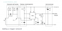
ive looked at page 7, but i dont know if you mean the timing RC or the trigger RC.
EDIT: ok so i think you mean lessening the 10nF cap on the input section.
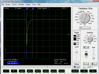
960uS is way to long
EDIT: ive got it down to 40uS, by going to 1nF, im just not sure how low in capacitience i can go. im going to try 500pF.
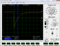
ive got the pulse to stay above 1.7 volts for 5.1uS.
it still doesnt work...Id like to have this graded by tuesday, my professor was impressed i etched a board, instead of just breadboarding. No matter what i do the output of the 555 stays at 5v. im ching the RC compentts ...
Patrick, Sun Oct 05 2014, 07:14PM
Sulaiman wrote ...
The trigger pulse for a 555 in monostable mode
MUST return high at least 10 us before the end of the timer period.
This is commonly achieved by putting a capacitor in series with the trigger signal
and a pull-up resistor from +Vs to the trigger pin.
R.C for the trigger input must be smaller than the timer period.
(google 555, download 555 datasheet from ti.com, see page 7 )
e.g. R=10k, C=100pF .... t = 1 us

ive looked at page 7, but i dont know if you mean the timing RC or the trigger RC.
EDIT: ok so i think you mean lessening the 10nF cap on the input section.

960uS is way to long
EDIT: ive got it down to 40uS, by going to 1nF, im just not sure how low in capacitience i can go. im going to try 500pF.

ive got the pulse to stay above 1.7 volts for 5.1uS.
it still doesnt work...Id like to have this graded by tuesday, my professor was impressed i etched a board, instead of just breadboarding. No matter what i do the output of the 555 stays at 5v. im ching the RC compentts ...
Re: High Voltage Planar Ferrite transformers. ( Intial Experiments )
Patrick, Mon Oct 06 2014, 03:25PM
im thinking of using a operational amplifier to run of the spike.
Patrick, Mon Oct 06 2014, 03:25PM
im thinking of using a operational amplifier to run of the spike.
Re: High Voltage Planar Ferrite transformers. ( Intial Experiments )
Newton Brawn, Tue Oct 07 2014, 04:02AM
Do you have enough space in the ferrite for secondary coil and such insulation ?
Newton Brawn, Tue Oct 07 2014, 04:02AM
Do you have enough space in the ferrite for secondary coil and such insulation ?
Re: High Voltage Planar Ferrite transformers. ( Intial Experiments )
Patrick, Tue Oct 07 2014, 04:19AM
I found this site:
for pic micros'
Patrick, Tue Oct 07 2014, 04:19AM
Newton Brawn wrote ...
Do you have enough space in the ferrite for secondary coil and such insulation ?
yep, it's all been calculated and measured. I'll be 3D printing it and wet winding it in epoxy.Do you have enough space in the ferrite for secondary coil and such insulation ?
I found this site:

for pic micros'
Re: High Voltage Planar Ferrite transformers. ( Intial Experiments )
Patrick, Tue Oct 07 2014, 08:48PM
no more BS, im doing it this way:

I'm so depressed, I can't even get the timer0 to blink an LED.
Patrick, Tue Oct 07 2014, 08:48PM
no more BS, im doing it this way:


I'm so depressed, I can't even get the timer0 to blink an LED.
Re: High Voltage Planar Ferrite transformers. ( Intial Experiments )
Shrad, Wed Oct 08 2014, 07:46AM
if one wants I have an explorer16 with pic16, pic24 and pic32 modules for sale, 100€ for the whole
the internal programmer of the explorer16 has been flashed with the pickit2 firmware and is able to program the chip in place without the need of an external programmer
Shrad, Wed Oct 08 2014, 07:46AM
if one wants I have an explorer16 with pic16, pic24 and pic32 modules for sale, 100€ for the whole
the internal programmer of the explorer16 has been flashed with the pickit2 firmware and is able to program the chip in place without the need of an external programmer
Re: High Voltage Planar Ferrite transformers. ( Intial Experiments )
Patrick, Wed Oct 08 2014, 08:18AM
I need to learn how to program first, so far im terrible.
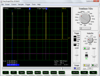
repition rate is 268 uS.
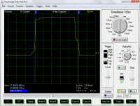
with component tolerance and temp stability 9.7uS is close enough.
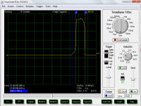
seen here, at 2uS a 1400 ohm resistor used, but I had to increase that to 10k (to get 9.7 uS), the difference in the math versus actual, I think was due to very low capacitance and leakage through the comparator.
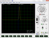
So now a 3.7kHz repeating pulse of 10uS has been achieved. This will be fed to the gate driver. Ill get my better CRT oscilloscope out tomorrow since the wave looks like its all block-ish, from lack of bandwidth.
Patrick, Wed Oct 08 2014, 08:18AM
I need to learn how to program first, so far im terrible.

repition rate is 268 uS.

with component tolerance and temp stability 9.7uS is close enough.

seen here, at 2uS a 1400 ohm resistor used, but I had to increase that to 10k (to get 9.7 uS), the difference in the math versus actual, I think was due to very low capacitance and leakage through the comparator.

So now a 3.7kHz repeating pulse of 10uS has been achieved. This will be fed to the gate driver. Ill get my better CRT oscilloscope out tomorrow since the wave looks like its all block-ish, from lack of bandwidth.
Re: High Voltage Planar Ferrite transformers. ( Intial Experiments )
Patrick, Thu Oct 16 2014, 07:41AM
Having huge problems
ive never seen this undulating waveform before through a resistive load. I don't know if its just the RC coupled with the linear regulator or not (at 9.8mF x 100ohms I doubt it). Im tempted to use a car battery to rule this in or out. The fact that the waveform is so well defined and uniformly repeated makes me think theres a definite mode ive missed.
I can confirm power is definitely switched through the MOSFET to the resistor. The MOSFET is almost not warm, (in fact I think its the resistor heating the MOSFET) The 100 ohm resistor gets flaming hot, so I run it 20 seconds at a time. the resistor obviously has the bizarre waveform across it. The duty cycle is 3.7% high. It all looks good, it just undulates oddly.
One last thing, when I put the probe ground to the source, and the tip to the gate. I see a perfect chopped waveform, no noise or V drop. there doesn't seem to be any stray noise to the wire loops from the 555 either.
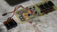
Finished modifications to the main board, 555 and the FAN7382 are both working.
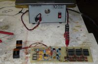
caps are connected, power supply was measured while running at 13.7 Vdc, this is a linear transformer power supply, it whiehgs a freaking ton.
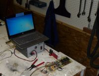
Overall setup to operate and data capture.

Power caps are 8,900uF electrolytic + 2.70 uF metal film.
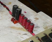
cap bank and twisted pair power lines.
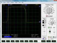
Verification of the 555 timer astable output, 10uS at 4.3 volts.
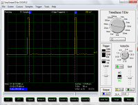
265uS off time from 555. Total period was verified to be 275uS.
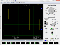
11.4 volts out of the gate driver to MOSFET gate. Regulator input to the gate IC was 11.97 volts.
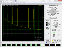
11.5 volts from the main PSU is being chopped, but its riding a bizarre wave form. There are no inductive components present, just a 100 ohm resistor. And this waveform across the resistor.
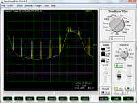
Another full period of the garbage waveform. It repeats quite predictably. (all of the pulses are present but my USB oscilloscope misses some fast moving stuff when zoomed so far out.
Ill get out my 100MHz o-scope if needed.
Patrick, Thu Oct 16 2014, 07:41AM
Having huge problems
ive never seen this undulating waveform before through a resistive load. I don't know if its just the RC coupled with the linear regulator or not (at 9.8mF x 100ohms I doubt it). Im tempted to use a car battery to rule this in or out. The fact that the waveform is so well defined and uniformly repeated makes me think theres a definite mode ive missed.
I can confirm power is definitely switched through the MOSFET to the resistor. The MOSFET is almost not warm, (in fact I think its the resistor heating the MOSFET) The 100 ohm resistor gets flaming hot, so I run it 20 seconds at a time. the resistor obviously has the bizarre waveform across it. The duty cycle is 3.7% high. It all looks good, it just undulates oddly.
One last thing, when I put the probe ground to the source, and the tip to the gate. I see a perfect chopped waveform, no noise or V drop. there doesn't seem to be any stray noise to the wire loops from the 555 either.

Finished modifications to the main board, 555 and the FAN7382 are both working.

caps are connected, power supply was measured while running at 13.7 Vdc, this is a linear transformer power supply, it whiehgs a freaking ton.

Overall setup to operate and data capture.

Power caps are 8,900uF electrolytic + 2.70 uF metal film.

cap bank and twisted pair power lines.

Verification of the 555 timer astable output, 10uS at 4.3 volts.

265uS off time from 555. Total period was verified to be 275uS.

11.4 volts out of the gate driver to MOSFET gate. Regulator input to the gate IC was 11.97 volts.

11.5 volts from the main PSU is being chopped, but its riding a bizarre wave form. There are no inductive components present, just a 100 ohm resistor. And this waveform across the resistor.

Another full period of the garbage waveform. It repeats quite predictably. (all of the pulses are present but my USB oscilloscope misses some fast moving stuff when zoomed so far out.
Ill get out my 100MHz o-scope if needed.
Re: High Voltage Planar Ferrite transformers. ( Intial Experiments )
Shrad, Thu Oct 16 2014, 08:42AM
aren't you catching up some signals? the first thing I thought about when seeing your board was that you had no ground plane
I know 555's can be catchy... maybe your PSU is radiating a bit of mains?
EDIT: maybe you have a defective resistor too... I wouldn't use a cheap carbon one in that place but maybe a metal film... those are suppositions of course
Re: High Voltage Planar Ferrite transformers. ( Intial Experiments )
Patrick, Thu Oct 16 2014, 08:48AM
I was worried about a ground plane, but thought I'd etch this first, and use a single ground trace and 9 volt batteries for a first prototype.
I'm thinking of a wire wound resistor, but they have stray inductance.
I'm hoping that yellow and black twisted pair to the MOSFET wasn't a mistake.
Re: High Voltage Planar Ferrite transformers. ( Intial Experiments )
Shrad, Thu Oct 16 2014, 06:04PM
I think you'll see far less junk with a car battery indeed, and also with a dedicated scope as some computers can radiate too... laptops are not well earthed...
Shrad, Thu Oct 16 2014, 06:04PM
I think you'll see far less junk with a car battery indeed, and also with a dedicated scope as some computers can radiate too... laptops are not well earthed...
Re: High Voltage Planar Ferrite transformers. ( Intial Experiments )
Electra, Thu Oct 16 2014, 07:38PM
The output of the mosfet (Drain), and Ground should look like a +13.8v dc level with Negative going pulses (just like the gate drive but inverted). Since you show positive going pulses in the last photo superimposed on some vaguely looking 60hz wave, One possibility is your circuit may working ok, but the issue may lay with the scope grounding. If you attach the scope ground clip anywhere else but ground, or leave it off you will get strange results.
The 100 ohm resistor should'nt be getting so hot at such low duty cycle either. So something to investigate too.
Re: High Voltage Planar Ferrite transformers. ( Intial Experiments )
Patrick, Thu Oct 16 2014, 10:18PM
With the car battery i dont see any heat or switching. I may have killed the mosfet.
however a ground loop also worries me, if i ground with the scope, power supply and USB/laptop, thats 3 points trying to ground.
EDIT: FIXED IT !!!
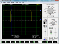
Grounding the USB shield to the PSU negative terminal, imeadiatley turned it into the above wave form. And the resistor doesn't even get warm, the previous undulations must have created a higher duty cycle, and or not fully triggered MOSFET conduction. ( and youll notice the voltage switched is higher than any other voltage in the circuit, so its definatley PSU power going through)
Next up:
Differential measurements to be sure the resistor is seeing the wavform I want.
then, printing bobbins, and running a single loop primary.
EDIT2 : Finnally got some results !
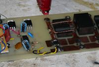
Placed primary.
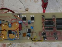
I don't know if this counts as 1.25 or 1 turn...
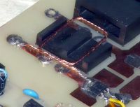
With out a safety resistor I think I blow out the MOSFETs with 200 Amp surges.
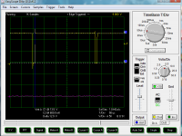
Here we see 10uS pulses of 13.5 V at 3.7kHz.
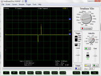
Here I think the primary series resistor limited the primary current too much, so the 1:3 ratio less than doubled the input voltage. 13.5V in, 23V out. I dont know why the output wave look like this, i expected a passive reset of the ferrite, but cant explain this or its short width.
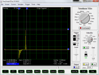
in this screen cap, the secondary ouput flickers between 57 and 64 Volts. this voltage appears when I reduce the primary safety resistor to 4.1 ohms. The squeeeeeeeeeeeeeeeal gets louder too. now 13.5 x 3 turns = 40.5 volts theoretical, so i think some of the excess voltage is from kickback. As there maybe a tiny airgap, due to temporary hotglue holding the ferrite halves together.
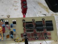
Exactly 3 full turns of the secondary wire.
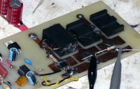
Seen in between the probe leads, a 680 ohm 1/2 watt resistor, across the secondary.
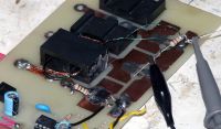
to the left, in series with the MOSFET and primary, a 4.1 ohm resistor. (15 || 10 || 10 = 4.1-ish ohms )
Patrick, Thu Oct 16 2014, 10:18PM
With the car battery i dont see any heat or switching. I may have killed the mosfet.
Electra wrote ...
The output of the mosfet (Drain), and Ground should look like a +13.8v dc level with Negative going pulses (just like the gate drive but inverted).
I thought of this while laying in bed, but now i cant see any signal across the load resistor. ill try grounding my laptop through the USB shield.The output of the mosfet (Drain), and Ground should look like a +13.8v dc level with Negative going pulses (just like the gate drive but inverted).
however a ground loop also worries me, if i ground with the scope, power supply and USB/laptop, thats 3 points trying to ground.
EDIT: FIXED IT !!!

Grounding the USB shield to the PSU negative terminal, imeadiatley turned it into the above wave form. And the resistor doesn't even get warm, the previous undulations must have created a higher duty cycle, and or not fully triggered MOSFET conduction. ( and youll notice the voltage switched is higher than any other voltage in the circuit, so its definatley PSU power going through)
Next up:
Differential measurements to be sure the resistor is seeing the wavform I want.
then, printing bobbins, and running a single loop primary.
EDIT2 : Finnally got some results !

Placed primary.

I don't know if this counts as 1.25 or 1 turn...

With out a safety resistor I think I blow out the MOSFETs with 200 Amp surges.

Here we see 10uS pulses of 13.5 V at 3.7kHz.

Here I think the primary series resistor limited the primary current too much, so the 1:3 ratio less than doubled the input voltage. 13.5V in, 23V out. I dont know why the output wave look like this, i expected a passive reset of the ferrite, but cant explain this or its short width.

in this screen cap, the secondary ouput flickers between 57 and 64 Volts. this voltage appears when I reduce the primary safety resistor to 4.1 ohms. The squeeeeeeeeeeeeeeeal gets louder too. now 13.5 x 3 turns = 40.5 volts theoretical, so i think some of the excess voltage is from kickback. As there maybe a tiny airgap, due to temporary hotglue holding the ferrite halves together.

Exactly 3 full turns of the secondary wire.

Seen in between the probe leads, a 680 ohm 1/2 watt resistor, across the secondary.

to the left, in series with the MOSFET and primary, a 4.1 ohm resistor. (15 || 10 || 10 = 4.1-ish ohms )
Re: High Voltage Planar Ferrite transformers. ( Intial Experiments )
Patrick, Fri Oct 17 2014, 07:53PM
Im going to try all three cores later today (ive got to get my drone finished and graded by my professors soon first) but i still have some problems, as identified in the above post which i edited recently with new info.
Patrick, Fri Oct 17 2014, 07:53PM
Im going to try all three cores later today (ive got to get my drone finished and graded by my professors soon first) but i still have some problems, as identified in the above post which i edited recently with new info.
Re: High Voltage Planar Ferrite transformers. ( Intial Experiments )
Electra, Fri Oct 17 2014, 11:40PM
To get your LR time constant longer you'll need to reduce R.
t = L/R
If your mosfet can take 50A try R= 0.22 ohm. With only a 30v device you'll have to do something serious to clamp the back emf of the primary, or it'll almost certainly kill the mosfet by over voltage . A simple Zenner will probably be destroyed, unless you have a stupidly big one. If you got the secondary load calculated correct most of the energy should be transferred to that, but you always get some leakage.
Re: High Voltage Planar Ferrite transformers. ( Intial Experiments )
Patrick, Sun Oct 19 2014, 08:21AM
so if your advising me to reduce it to 0.22 ohms, what is the T or L value you used to arrive at 0.22 ohms? i presume one of my oscillograms led you to this conclusion.
Patrick, Sun Oct 19 2014, 08:21AM
so if your advising me to reduce it to 0.22 ohms, what is the T or L value you used to arrive at 0.22 ohms? i presume one of my oscillograms led you to this conclusion.
Re: High Voltage Planar Ferrite transformers. ( Intial Experiments )
Electra, Sun Oct 19 2014, 07:52PM
The narrow pulses you see, is I think a result of the value of L being small, whether it is too small or not I don't know. For a conventional transformer the magnetizing current from the inductance might be something typically in the order of 5%, of the full load current.
I guess if you had a value for L, and you assumed it to be operating a continuous mode, the 10us would be for each half cycle I assume, so f= 50 khz you could get an aprox value of your reactance, and therefore the reactive current. (there's gota be a mathematical correct way using differentiation to work it out too).
A Value of 0.22 ohm (of a few watts) would limit the total peak current by default (ohms law), to well actually just over 60A in the worst case, with the psu still at 13.8 v. If you can't get a nice rectangular pulse through it by then. You need more turns after all, or reduce the pulse width and increase the frequency.
You don't need R once you are confident it works it only wastes power. Of course you know that.
I'm not suggesting running it unloaded, as it's not unlike a flyback as you have built it. Higher voltage FETs would have been ideal I suppose.
Don't mean to be critical in a negative way, just trying to input some ideas, even if I'm not always on the right track others can fill in the gaps.
Re: High Voltage Planar Ferrite transformers. ( Intial Experiments )
Sulaiman, Sun Oct 19 2014, 08:16PM
With short pulses you should try to minimise leakage/stray inductance as much as possible,
this basically means having all conductors ( cap+ to coil to transistor to cap- ) as short as possible
and minimising the loop area that your conductors form / the current flows
putting the caps nearer/on the pcb will help
you may find a different primary winding better, marked in red;
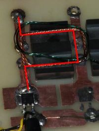
I agree with the point about testing with a load,
reducing voltage stress on the switching transistors.
Sulaiman, Sun Oct 19 2014, 08:16PM
With short pulses you should try to minimise leakage/stray inductance as much as possible,
this basically means having all conductors ( cap+ to coil to transistor to cap- ) as short as possible
and minimising the loop area that your conductors form / the current flows
putting the caps nearer/on the pcb will help
you may find a different primary winding better, marked in red;

I agree with the point about testing with a load,
reducing voltage stress on the switching transistors.
Re: High Voltage Planar Ferrite transformers. ( Intial Experiments )
Patrick, Sun Oct 19 2014, 09:20PM
Patrick, Sun Oct 19 2014, 09:20PM
Sulaiman wrote ...
you may find a different primary winding better, marked in red;

I agree with the point about testing with a load,
reducing voltage stress on the switching transistors.
but i thought this path was less desirable.you may find a different primary winding better, marked in red;

I agree with the point about testing with a load,
reducing voltage stress on the switching transistors.
Re: High Voltage Planar Ferrite transformers. ( Intial Experiments )
Sulaiman, Sun Oct 19 2014, 09:50PM
You have the setup,
try the two and see the difference.
Then let us (me) know :)
I'm fairly confident that it will reduce leakage/parasitic/wasted external inductance
and if you consider the whole circuit for current, it's still one full turn for the single core
Sulaiman, Sun Oct 19 2014, 09:50PM
You have the setup,
try the two and see the difference.
Then let us (me) know :)
I'm fairly confident that it will reduce leakage/parasitic/wasted external inductance
and if you consider the whole circuit for current, it's still one full turn for the single core
Re: High Voltage Planar Ferrite transformers. ( Intial Experiments )
Uspring, Mon Oct 20 2014, 04:11AM
Electra wrote:
dI/dt = V/L and
Imax = V/R
The time the current will rise, which is about the width of the secondary voltage peak is then roughly
t = Imax / (dI/dt) = L/R
That is Electras equation.
As far as I can see from the scope shot, the voltage peak is maybe about 1us long. In order to obtain a reasonably faithful reproduction of the 10us input pulse, t should be at least 10 times as large either by increasing L as Sulaiman suggests or by decreasing R as Electra does.
Eventually you'll want to get rid of a current limiting resistor, so the only way of keeping the current within limits is to increase inductance. Inductance can be greatly reduced by gaps in the ferrite. You have to be extremely careful of avoiding that when glueing the pieces together. A preliminary ballpark estimate I made seems to suggest that you have a considerably lower inductance than expected considering the high u material you are using.
Uspring, Mon Oct 20 2014, 04:11AM
Electra wrote:
The narrow pulses you see, is I think a result of the value of L being small...Precisely. When you apply a voltage to an inductance it will cause a linear rise in current. This rise will finally be limited by the series resistance. Quantitatively:
dI/dt = V/L and
Imax = V/R
The time the current will rise, which is about the width of the secondary voltage peak is then roughly
t = Imax / (dI/dt) = L/R
That is Electras equation.
As far as I can see from the scope shot, the voltage peak is maybe about 1us long. In order to obtain a reasonably faithful reproduction of the 10us input pulse, t should be at least 10 times as large either by increasing L as Sulaiman suggests or by decreasing R as Electra does.
Eventually you'll want to get rid of a current limiting resistor, so the only way of keeping the current within limits is to increase inductance. Inductance can be greatly reduced by gaps in the ferrite. You have to be extremely careful of avoiding that when glueing the pieces together. A preliminary ballpark estimate I made seems to suggest that you have a considerably lower inductance than expected considering the high u material you are using.
Re: High Voltage Planar Ferrite transformers. ( Intial Experiments )
Patrick, Mon Oct 20 2014, 05:14AM
OK so let me try reducing the resistance and decreasing the time interval to 5 uS, that should help, right? Im also using passive reset, which i gather you all figured out the long off times were for. (The whole point of this project is high power at high effceincy, so the resistance is unwanted, eventually. Im using it to avoid blowing components though.) sulaimans idea worries me as i was trying to get away from fractional turns.
here in this thread: (typical TV flyback)
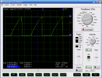
Current profile through flyback and 0.5 Ohm resistor, (Primary current), peaks at 5.8 V, so 5.8V / 0.5 Ohms = 11.6 peak amps.
Patrick, Mon Oct 20 2014, 05:14AM
Uspring wrote ...
Electra wrote:
dI/dt = V/L and
Imax = V/R
The time the current will rise, which is about the width of the secondary voltage peak is then roughly
t = Imax / (dI/dt) = L/R
That is Electras equation.
Ah yes i see, the constant slope (nearly) triangle ive seen before.Electra wrote:
The narrow pulses you see, is I think a result of the value of L being small...Precisely. When you apply a voltage to an inductance it will cause a linear rise in current. This rise will finally be limited by the series resistance. Quantitatively:
dI/dt = V/L and
Imax = V/R
The time the current will rise, which is about the width of the secondary voltage peak is then roughly
t = Imax / (dI/dt) = L/R
That is Electras equation.
OK so let me try reducing the resistance and decreasing the time interval to 5 uS, that should help, right? Im also using passive reset, which i gather you all figured out the long off times were for. (The whole point of this project is high power at high effceincy, so the resistance is unwanted, eventually. Im using it to avoid blowing components though.) sulaimans idea worries me as i was trying to get away from fractional turns.
here in this thread:
 (typical TV flyback)
Current profile through flyback and 0.5 Ohm resistor, (Primary current), peaks at 5.8 V, so 5.8V / 0.5 Ohms = 11.6 peak amps.
Re: High Voltage Planar Ferrite transformers. ( Intial Experiments )
Uspring, Mon Oct 20 2014, 05:56AM
Yes, that should help. But, as said, you'll want to get rid of the series resistor, since it'll eat up lots of power. From your scope shot my guess at the primary inductance is from
a) Current rise speed: 0.4A/us
b) Applied voltage 13V (?)
c) L = V / (dI/dt)
That will amount to roughly 30uH inductance. If you run that with 100kHz frequency, reactance will be 2*pi*f*L or about 20 ohms. Assuming a 100V peak to peak or 50V peak input, the magnetizing current will be 2.5A peak. This is with an unloaded secondary. As soon as you load the secondary the current will increase. If you finally want to work with 50A peak (i.e. with loaded secondary), the amount of magnetizing current alone looks reasonable.
You have a rapid drop of current in the primary. You must be generating a huge voltage peak somewhere.
Re: High Voltage Planar Ferrite transformers. ( Intial Experiments )
Patrick, Mon Oct 20 2014, 06:07AM
Patrick, Mon Oct 20 2014, 06:07AM
Uspring wrote ...
You must be generating a huge voltage peak somewhere.
Im hoping its at the 3 turn secondary, i was getting 63 volts or so across a 680 ohm resistor. I disabled the gate and source-drain TVS, to prevent "missing voltage" but the internal body zener is beyond reach. You must be generating a huge voltage peak somewhere.
Re: High Voltage Planar Ferrite transformers. ( Intial Experiments )
Ash Small, Mon Oct 20 2014, 06:21AM
I'm not sure it is 'fractional turns'. It passes through both winding windows. For example, with a toroidal core, the wire only needs to pass through the toroid to be a 'full turn'.
What I'd do is move the MOSFET and the positive feed as close as possible to the window itself. In the circuit I'm working on (which operates in 'flyback mode') I'll have a capacitor between the drain on the MOSFET and the primary. (EDITED, I made a mistake. I think it's correct now, but I've been up all night)
I'm not sure if all this is applicable to your circuit (I'm planning on having three or four MOSFET's per primary turn, and a solid aluminium primary, but I'm using toroidal cores). My primary pulse length will be around 100nS, I hope.
Ash Small, Mon Oct 20 2014, 06:21AM
Patrick wrote ...
sulaimans idea worries me as i was trying to get away from fractional turns.
sulaimans idea worries me as i was trying to get away from fractional turns.
I'm not sure it is 'fractional turns'. It passes through both winding windows. For example, with a toroidal core, the wire only needs to pass through the toroid to be a 'full turn'.
What I'd do is move the MOSFET and the positive feed as close as possible to the window itself. In the circuit I'm working on (which operates in 'flyback mode') I'll have a capacitor between the drain on the MOSFET and the primary. (EDITED, I made a mistake. I think it's correct now, but I've been up all night)
I'm not sure if all this is applicable to your circuit (I'm planning on having three or four MOSFET's per primary turn, and a solid aluminium primary, but I'm using toroidal cores). My primary pulse length will be around 100nS, I hope.
Re: High Voltage Planar Ferrite transformers. ( Intial Experiments )
Patrick, Mon Oct 20 2014, 06:31AM
Im fine with redesigning the layout, given the great progress so far. in fact ill get rid of the gate driver IC and 555. the next version will have a single UC28023DW from TI.
Patrick, Mon Oct 20 2014, 06:31AM
Im fine with redesigning the layout, given the great progress so far. in fact ill get rid of the gate driver IC and 555. the next version will have a single UC28023DW from TI.
Re: High Voltage Planar Ferrite transformers. ( Intial Experiments )
Patrick, Tue Oct 21 2014, 02:48AM
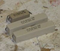
I bought some common wire wound resistors, 0.47 and 1 ohm, +- 10%.
After "liberating" the wire from the mineral wool, it measures 5.6 inches for 0.47 ohms.
Im wanting 0.15 ohms. So, 0.47 / 5.6 = 0.084 ohms per inch. 0.15 / 0.084 = 1.79 inchs.
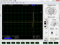
Primary voltage between Drain and lower transformer terminal, not sure why its mysteriously higher than 13.5 Vin. These two primary and secvondary waveforms do look like each other, so that's an improvement.
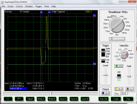
Seen here the new oscillogram, 5 uS and 0.15 ohms in series. reaches 113 V on the secondary. It absolutely squeals when it runs. when I tried this at 10uS and 0.15 ohms, the resistor started to glow bright nuclear orange. repeating with new resistor at 5uS did not reveal much heat, the mosfet and copper were noticeable warm, but I don't know if that heat came from the internal diode or the resistor.

Resistor that went incandescent is outlined in blue with arrow.
im not real sure what the oscillogram means though, it looks like a more defined version of the previous posts. so I assume the previous points you all have made are right, the t=L/r thing is dominating here. I just don't see why the shape is a spike. or why there is a square-ish dip before the spike. Whats exciting is the secondary dip and spike are proportional to the 1:3 turns rate at the primary, as it should be.

A thought for this primary side pic, if I take more power out of the secondary, will the sharp 26 volt peak start to diminish?
Patrick, Tue Oct 21 2014, 02:48AM

I bought some common wire wound resistors, 0.47 and 1 ohm, +- 10%.

After "liberating" the wire from the mineral wool, it measures 5.6 inches for 0.47 ohms.
Im wanting 0.15 ohms. So, 0.47 / 5.6 = 0.084 ohms per inch. 0.15 / 0.084 = 1.79 inchs.

Primary voltage between Drain and lower transformer terminal, not sure why its mysteriously higher than 13.5 Vin. These two primary and secvondary waveforms do look like each other, so that's an improvement.

Seen here the new oscillogram, 5 uS and 0.15 ohms in series. reaches 113 V on the secondary. It absolutely squeals when it runs. when I tried this at 10uS and 0.15 ohms, the resistor started to glow bright nuclear orange. repeating with new resistor at 5uS did not reveal much heat, the mosfet and copper were noticeable warm, but I don't know if that heat came from the internal diode or the resistor.

Resistor that went incandescent is outlined in blue with arrow.
im not real sure what the oscillogram means though, it looks like a more defined version of the previous posts. so I assume the previous points you all have made are right, the t=L/r thing is dominating here. I just don't see why the shape is a spike. or why there is a square-ish dip before the spike. Whats exciting is the secondary dip and spike are proportional to the 1:3 turns rate at the primary, as it should be.

A thought for this primary side pic, if I take more power out of the secondary, will the sharp 26 volt peak start to diminish?
Re: High Voltage Planar Ferrite transformers. ( Intial Experiments )
Patrick, Wed Oct 22 2014, 03:05AM
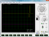
no added resistor, just the primary and MOSFET. it ran just fine for a while, then blew the MOSFET while making a bad measurement.
I don't know why that dip is in front. it hurts my brain.
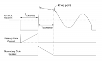
Im wondering if its mode is close to that of a flybaack.
EDIT: Im wandering if there should be a diode to prevent the reverse voltage. a diode above the transistor but below the coil.
 STTH30L06G-TR
Patrick, Wed Oct 22 2014, 03:05AM

no added resistor, just the primary and MOSFET. it ran just fine for a while, then blew the MOSFET while making a bad measurement.
I don't know why that dip is in front. it hurts my brain.

Im wondering if its mode is close to that of a flybaack.
EDIT: Im wandering if there should be a diode to prevent the reverse voltage. a diode above the transistor but below the coil.
 STTH30L06G-TR
Re: High Voltage Planar Ferrite transformers. ( Intial Experiments )
Shrad, Wed Oct 22 2014, 10:32AM
that's just a bet, but what about your three cores arranged 120° apart at one side of the PCB and the three mosfets the other side, with the secondary in the same form as a triskel?
Shrad, Wed Oct 22 2014, 10:32AM
that's just a bet, but what about your three cores arranged 120° apart at one side of the PCB and the three mosfets the other side, with the secondary in the same form as a triskel?
Re: High Voltage Planar Ferrite transformers. ( Intial Experiments )
Uspring, Wed Oct 22 2014, 10:53AM
If that's secondary voltage you are looking at, primary voltage probably looks quite like it.
When you apply a positive voltage pulse to the primary, the current will rise until the pulse ends. Then the current will stay on and drive your input negative. If you don't clamp it, voltage will go to a value where something gives and will clamp it.
The secondary will just reflect this behaviour, i.e. first a positive pulse with the width of the input pulse and then a negative one.
Re: High Voltage Planar Ferrite transformers. ( Intial Experiments )
Patrick, Wed Oct 22 2014, 07:20PM
So your suggesting the MOSFET diode is clamping the negative dip? (but will evetually get killed no doubt, this would explain excess heat too.)
but what do other SMPS makers do to get rid of this problem?
Patrick, Wed Oct 22 2014, 07:20PM
Uspring wrote ...
If that's secondary voltage you are looking at, primary voltage probably looks quite like it.
When you apply a positive voltage pulse to the primary, the current will rise until the pulse ends. Then the current will stay on and drive your input negative. If you don't clamp it, voltage will go to a value where something gives and will clamp it.
The secondary will just reflect this behaviour, i.e. first a positive pulse with the width of the input pulse and then a negative one.
ok but i get the negative pulse first, then the a positive one. and yes the primary and secondary waveforms are exactly the same but transformed by the turns ratio. If that's secondary voltage you are looking at, primary voltage probably looks quite like it.
When you apply a positive voltage pulse to the primary, the current will rise until the pulse ends. Then the current will stay on and drive your input negative. If you don't clamp it, voltage will go to a value where something gives and will clamp it.
The secondary will just reflect this behaviour, i.e. first a positive pulse with the width of the input pulse and then a negative one.
So your suggesting the MOSFET diode is clamping the negative dip? (but will evetually get killed no doubt, this would explain excess heat too.)
but what do other SMPS makers do to get rid of this problem?
Re: High Voltage Planar Ferrite transformers. ( Intial Experiments )
Electra, Wed Oct 22 2014, 09:52PM
Add another one turn winding tightly coupled to the primary, but opposite phase (got this image off Google to show what I mean) it's often used in forward converters. The diode returns the energy to the supply. It should be a schottky or fast diode I think.
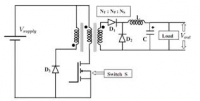
Electra, Wed Oct 22 2014, 09:52PM
Add another one turn winding tightly coupled to the primary, but opposite phase (got this image off Google to show what I mean) it's often used in forward converters. The diode returns the energy to the supply. It should be a schottky or fast diode I think.

Re: High Voltage Planar Ferrite transformers. ( Intial Experiments )
Patrick, Wed Oct 22 2014, 10:47PM
I dont see oscillograms of these negative dips in push-pull circuits though...
Patrick, Wed Oct 22 2014, 10:47PM
Electra wrote ...
Add another one turn winding tightly coupled to the primary, but opposite phase (got this image off Google to show what I mean) it's often used in forward converters. The diode returns the energy to the supply. It should be a schottky or fast diode I think.

Yes i've seen this too. maybe ill have to retry with this solution. My ultimate goal is a push-pull driven planar core bank of transformers. this was just a uni-polar prototype to shake out the issues with fractional or now distributed primaries. Add another one turn winding tightly coupled to the primary, but opposite phase (got this image off Google to show what I mean) it's often used in forward converters. The diode returns the energy to the supply. It should be a schottky or fast diode I think.

I dont see oscillograms of these negative dips in push-pull circuits though...
Re: High Voltage Planar Ferrite transformers. ( Intial Experiments )
Patrick, Thu Oct 23 2014, 05:15AM
Im going to make a differetntial measurement, to see what the real waveform is from terminal to terminal across the primary.
Patrick, Thu Oct 23 2014, 05:15AM
Im going to make a differetntial measurement, to see what the real waveform is from terminal to terminal across the primary.
Re: High Voltage Planar Ferrite transformers. ( Intial Experiments )
Uspring, Thu Oct 23 2014, 10:34AM

Uspring, Thu Oct 23 2014, 10:34AM
ok but i get the negative pulse first, then the a positive one. and yes the primary and secondary waveforms are exactly the same but transformed by the turns ratio.Swap the leads of your secondary and you'll get a positive pulse first

So your suggesting the MOSFET diode is clamping the negative dip? (but will evetually get killed no doubt, this would explain excess heat too.)You have a reverse diode in the FET? If you get a lot of (forward) voltage across it, I'm surprised, that it hasn't blown immediately.
Re: High Voltage Planar Ferrite transformers. ( Intial Experiments )
Patrick, Thu Oct 23 2014, 03:32PM
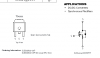
Diode.
Patrick, Thu Oct 23 2014, 03:32PM
Uspring wrote ...

but if i change the leads, i think ill blow the ground loop. [laptop:PS:Board] all on the same ground potential.ok but i get the negative pulse first, then the a positive one. and yes the primary and secondary waveforms are exactly the same but transformed by the turns ratio.Swap the leads of your secondary and you'll get a positive pulse first

So your suggesting the MOSFET diode is clamping the negative dip? (but will evetually get killed no doubt, this would explain excess heat too.)You have a reverse diode in the FET? If you get a lot of (forward) voltage across it, I'm surprised, that it hasn't blown immediately.

Diode.
Re: High Voltage Planar Ferrite transformers. ( Intial Experiments )
Patrick, Fri Oct 24 2014, 05:51AM
I dont get a diferent result even using a battery and isolated (but still grounded to the battery) USB/laptop.
That means the negative dip is real and not a fictitious artifact.
It turns out i blew the MOSFET and gate drive IC. in last nights run. this nights run i blew another MOSFET, but the driver is OK. I dont have many drivers left, and cant run more tests till i get someones better idea of whats going on, instead of my random guessing and poking around.
I dont know what to do...
EDIT 1: this pantent seems to show a similar primary voltage waveform, inverted, as uspring said.
EDIT 2: Crazy though, crazy thought... what if my incomplete plans for a push-pull circuit are suffering from, the missing half of the primary. Perhaps the opposite side of the energized primary serves the purpose of the forward converters' diode and tertiary winding?
Patrick, Fri Oct 24 2014, 05:51AM
I dont get a diferent result even using a battery and isolated (but still grounded to the battery) USB/laptop.
That means the negative dip is real and not a fictitious artifact.
It turns out i blew the MOSFET and gate drive IC. in last nights run. this nights run i blew another MOSFET, but the driver is OK. I dont have many drivers left, and cant run more tests till i get someones better idea of whats going on, instead of my random guessing and poking around.
I dont know what to do...
EDIT 1: this pantent seems to show a similar primary voltage waveform, inverted, as uspring said.

EDIT 2: Crazy though, crazy thought... what if my incomplete plans for a push-pull circuit are suffering from, the missing half of the primary. Perhaps the opposite side of the energized primary serves the purpose of the forward converters' diode and tertiary winding?
Re: High Voltage Planar Ferrite transformers. ( Intial Experiments )
Uspring, Fri Oct 24 2014, 10:17AM
I should habe looked at the circuit you posted initially. When the fet starts conducting it will cause a current rise in the primary, which causes the negative pulse in the secondary. When it stops conducting, the primary inductance will cause a positive voltage jump until the zener conducts. That causes the positive secondary pulse. That is similar to a flyback operation. The zener will have to take all the power of the pulse, which might cause it to blow. If it blows, there is nothing to prevent a huge voltage rise, which might blow the fet.
I'd connect a diode from the power supply rail to the drain of the fet, so that it becomes conducting, when the drain voltage is pushed above the power supply voltage. That will feed the energy back into the supply electrolytics. The diode should have a current rating at least of that of the fet.
Probably the whole thing gets better once you implement the other half of the push-pull and the secondary is loaded.
Re: High Voltage Planar Ferrite transformers. ( Intial Experiments )
Patrick, Fri Oct 24 2014, 03:45PM
Should the diode from Drain to V+ be arranged as in the forward circuit, but with out the tertiary winding?
The method of failure you describe, is what i had suspected, and fits whats been seen and smelled.
EDIT 1 : check my reasoning, with the law of induction, current change is opposed by voltage, so building current could appear as a dip, intrupted current would have the opposite voltage sign? Thus the diode.
EDIT 2 :
Forward converter modified circuit, now seems to be the solution. the external diodes do get hot after 20 seconds, but the MOSFET is cool or cold, which wasn't the case before. so if youll notice from previous posts, those inexplicable high spikes are gone. Only the primary dip is seen in the following, as the primary is temporarily grounded to grab current. it seems 96mA is conducted for each pulse at the secondary through 400 ohm at 38 V.
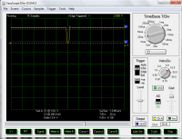 13.4 volt dip from the conduction of the FET. This pulse looks profoundly different. It also has a deafening HOWL when it runs, much louder than before.
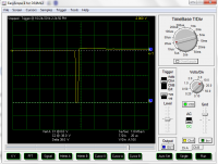
Secondary pulse (loaded 400 ohms), looks real good. 38 volts, and duration is right. Now heres the great part, 38 / 13.4 = 2.8 withch means a 1:3 or 1.1:3 turns ratio, very close to actual and exciting, ill be moving on to two cores and primaries, with a single seconday. The tail edge "bump" looks greatly lengthen, i think due to the RL constant.
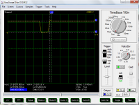
Primary pulse showing a zoom in on that little peak or ring, its 1.4 volts by 800nS. not sure if this matters or will disappear with a true push-pull circuit. that little peak or bump might be the diode going out of conduction when the spike is ending.
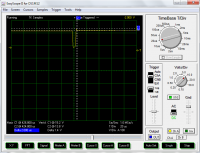
primary pulse.
Patrick, Fri Oct 24 2014, 03:45PM
Should the diode from Drain to V+ be arranged as in the forward circuit, but with out the tertiary winding?
The method of failure you describe, is what i had suspected, and fits whats been seen and smelled.
EDIT 1 : check my reasoning, with the law of induction, current change is opposed by voltage, so building current could appear as a dip, intrupted current would have the opposite voltage sign? Thus the diode.
EDIT 2 :
Forward converter modified circuit, now seems to be the solution. the external diodes do get hot after 20 seconds, but the MOSFET is cool or cold, which wasn't the case before. so if youll notice from previous posts, those inexplicable high spikes are gone. Only the primary dip is seen in the following, as the primary is temporarily grounded to grab current. it seems 96mA is conducted for each pulse at the secondary through 400 ohm at 38 V.
 13.4 volt dip from the conduction of the FET. This pulse looks profoundly different. It also has a deafening HOWL when it runs, much louder than before.
Secondary pulse (loaded 400 ohms), looks real good. 38 volts, and duration is right. Now heres the great part, 38 / 13.4 = 2.8 withch means a 1:3 or 1.1:3 turns ratio, very close to actual and exciting, ill be moving on to two cores and primaries, with a single seconday. The tail edge "bump" looks greatly lengthen, i think due to the RL constant.

Primary pulse showing a zoom in on that little peak or ring, its 1.4 volts by 800nS. not sure if this matters or will disappear with a true push-pull circuit. that little peak or bump might be the diode going out of conduction when the spike is ending.

primary pulse.
Re: High Voltage Planar Ferrite transformers. ( Intial Experiments )
Electra, Sat Oct 25 2014, 12:39AM
Ok remember , volts x second product have to be the same for positive and negative. The negative part as you call it, is the on time of the mosfet the rectangular pulse (which comes first). Next you see the tall but narrower positive pulse, which is determined by how fast the flux can decay, so it chooses it own level depending on what's limiting it.
By the looks of your latest scope shots you've clamped this completely with a diode. I guess you are getting away with this because the off time is so long, ordinarily it would cause a d.c bias in the core, but hay if it works.
I agree with Uspring, that the positive spike, combined with the low voltage rating is probably what's killing them Fets.
Yes think you have it right, push pull is in a way like two forward converters in a mirror image of each other operating alternately.
In push pull your mosfets will see 2x Vin, plus maybe a bit of a spike from any leakage inductance on top, I would have thought choosing 60v or more mosfets if you can, would be reasonable.
Have also seen diodes placed in parallel to the mosfets, then these can be 'better' diodes than the internal ones, and take some of the heat dissipation off the mosfets.
Perhaps look at trying to get big variable power supply for testing the scaled up push pull version, so you can turn it down if it gets too hot, too fast.
Re: High Voltage Planar Ferrite transformers. ( Intial Experiments )
Patrick, Sat Oct 25 2014, 02:04AM
Saturation due to flux walking wont be a problem in the final push-pull configuration.

YEEEEEEEEEEEEEEEOOOOOOOOOOOOOWWWWWWW!!!!!!!!!!!
74.8 V / 3 turns = 25 volts per turn, that's just 2 cores! wait till I get to 5!
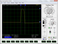
Patrick, Sat Oct 25 2014, 02:04AM
Electra wrote ...
Ok remember , volts x second product have to be the same for positive and negative. The negative part as you call it, is the on time of the mosfet the rectangular pulse (which comes first). Next you see the tall but narrower positive pulse, which is determined by how fast the flux can decay, so it chooses it own level depending on what's limiting it.
Yes, I assume this is seen to trail off in the secondary pics as an RL time product...Ok remember , volts x second product have to be the same for positive and negative. The negative part as you call it, is the on time of the mosfet the rectangular pulse (which comes first). Next you see the tall but narrower positive pulse, which is determined by how fast the flux can decay, so it chooses it own level depending on what's limiting it.
Electra wrote ...
By the looks of your latest scope shots you've clamped this completely with a diode. I guess you are getting away with this because the off time is so long, ordinarily it would cause a d.c bias in the core, but hay if it works.
Normally I wouldn't do this, as "flux walking" inevitably leads saturation and blown components, or poor power supplies that don't live long, but I really needed to verify some things with out the full push-pull complications. After all, this whole project was a wildly psychotic idea I wasn't even sure would work. By the looks of your latest scope shots you've clamped this completely with a diode. I guess you are getting away with this because the off time is so long, ordinarily it would cause a d.c bias in the core, but hay if it works.
Saturation due to flux walking wont be a problem in the final push-pull configuration.
Electra wrote ...
I agree with Uspring, that the positive spike, combined with the low voltage rating is probably what's killing them Fets.
Yes think you have it right, push pull is in a way like two forward converters in a mirror image of each other operating alternately.
In push pull your mosfets will see 2x Vin, plus maybe a bit of a spike from any leakage inductance on top, I would have thought choosing 60v or more mosfets if you can, would be reasonable.
I will be looking into the increased Vds of a MOSFET for the reasons you state, but I mainly wanted very low Rds for very high current applications. As we all know Rds creeps up with voltage. I agree with Uspring, that the positive spike, combined with the low voltage rating is probably what's killing them Fets.
Yes think you have it right, push pull is in a way like two forward converters in a mirror image of each other operating alternately.
In push pull your mosfets will see 2x Vin, plus maybe a bit of a spike from any leakage inductance on top, I would have thought choosing 60v or more mosfets if you can, would be reasonable.

Electra wrote ...
Have also seen diodes placed in parallel to the mosfets, then these can be 'better' diodes than the internal ones, and take some of the heat dissipation off the mosfets.
Perhaps look at trying to get big variable power supply for testing the scaled up push pull version, so you can turn it down if it gets too hot, too fast.
Yep, I was hoping to put TVS diodes in parallel both from gate to source and from drain to source. that move heat out of the MOSFET. And as you said the internal diodes are a fabrication artifact and not great.Have also seen diodes placed in parallel to the mosfets, then these can be 'better' diodes than the internal ones, and take some of the heat dissipation off the mosfets.
Perhaps look at trying to get big variable power supply for testing the scaled up push pull version, so you can turn it down if it gets too hot, too fast.
YEEEEEEEEEEEEEEEOOOOOOOOOOOOOWWWWWWW!!!!!!!!!!!
74.8 V / 3 turns = 25 volts per turn, that's just 2 cores! wait till I get to 5!

Re: High Voltage Planar Ferrite transformers. ( Intial Experiments )
Uspring, Sat Oct 25 2014, 11:03AM
Your primary is center tapped, so the voltages on the side are mirror symmetrical to the center. A positive voltage spike on the one side implies a negative one on the other. So once you put in the second fet, its reverse diode will do the clamping and it will also clamp the positive spike on the other fet. For testing I'd leave out the second fet and just install a reverse diode. You do need a complete primary for this, i.e. 2 turns in total, center tapped.
Where did you put the diode now? What is the tertiary winding? I thought you just had a primary and a secondary.
Uspring, Sat Oct 25 2014, 11:03AM
Should the diode from Drain to V+ be arranged as in the forward circuit, but with out the tertiary winding?What I meant was a diode across the primary so that it doesn't conduct when the fet turns on. But that is a terrible idea once you add the second fet. A better idea is to use a diode together with the other half of the primary.
Your primary is center tapped, so the voltages on the side are mirror symmetrical to the center. A positive voltage spike on the one side implies a negative one on the other. So once you put in the second fet, its reverse diode will do the clamping and it will also clamp the positive spike on the other fet. For testing I'd leave out the second fet and just install a reverse diode. You do need a complete primary for this, i.e. 2 turns in total, center tapped.
Where did you put the diode now? What is the tertiary winding? I thought you just had a primary and a secondary.
Re: High Voltage Planar Ferrite transformers. ( Intial Experiments )
Patrick, Sat Oct 25 2014, 03:27PM
I had to make a forward converter, thought this is what you meant, by adding a diode?
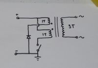
Otherwise where did you mean it to be?
Im just so relieved I can get to high volts per turn rates, as the math predicted.
So, with these 2 cores, a common secondary and two uncommon primaries, im getting an effective ratio of 0.5 to 3 which means 13.4 x 6 = 80, very close to 75 actual.
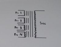
Ive never seen anyone else use this type of transformer or this mode of operation. So im not sure if I should be so bold as to claim a whole new type of transformer, but this is my chosen schematic diagram.
Patrick, Sat Oct 25 2014, 03:27PM
I had to make a forward converter, thought this is what you meant, by adding a diode?

Otherwise where did you mean it to be?
Im just so relieved I can get to high volts per turn rates, as the math predicted.
So, with these 2 cores, a common secondary and two uncommon primaries, im getting an effective ratio of 0.5 to 3 which means 13.4 x 6 = 80, very close to 75 actual.

Ive never seen anyone else use this type of transformer or this mode of operation. So im not sure if I should be so bold as to claim a whole new type of transformer, but this is my chosen schematic diagram.
Re: High Voltage Planar Ferrite transformers. ( Intial Experiments )
Uspring, Sat Oct 25 2014, 04:25PM
Yes, that's the way I'd connect the diode. It prevents a positive voltage surge at the switch, when you turn it off.
Uspring, Sat Oct 25 2014, 04:25PM
Yes, that's the way I'd connect the diode. It prevents a positive voltage surge at the switch, when you turn it off.
Re: High Voltage Planar Ferrite transformers. ( Intial Experiments )
Patrick, Sat Oct 25 2014, 04:37PM
this thread is nearing its end, so those of you who want to speak up should. Uspring, im already drafting the full push-pull circuit. so the diodes will be different, and I want others to see my schematic before I etch it.
I have to admit, I thought id blow out 20 plus MOSFETs getting this to work, but I only had 4 give up the smoke.
The rough push-pull will be:
UC28023DW --> FAN7382 --> MOSFETs --> Transformers
Ill have to get all new Gate drivers, MOSFETs and TVSs from mouser
Im looking at TVS's here:
MOSFETs
Im thinking the max input voltage should be 24 volts or so, plus some noise?
so that means at least 48 Vds.
New planar ferrite push-pull thread will start soon.
Patrick, Sat Oct 25 2014, 04:37PM
this thread is nearing its end, so those of you who want to speak up should. Uspring, im already drafting the full push-pull circuit. so the diodes will be different, and I want others to see my schematic before I etch it.
I have to admit, I thought id blow out 20 plus MOSFETs getting this to work, but I only had 4 give up the smoke.
The rough push-pull will be:
UC28023DW --> FAN7382 --> MOSFETs --> Transformers
Ill have to get all new Gate drivers, MOSFETs and TVSs from mouser
Im looking at TVS's here:

MOSFETs

Im thinking the max input voltage should be 24 volts or so, plus some noise?
so that means at least 48 Vds.
New planar ferrite push-pull thread will start soon.
Re: High Voltage Planar Ferrite transformers. ( Intial Experiments )
jpsmith123, Sun Oct 26 2014, 02:37PM
Hello Patrick,
I think your idea is what's generally known as a "voltage adder". The basic concept has been around for a while. There are particle accelerator designs based on this concept - both with and without ferrite cores - and I've seen various HV power supplies using transformers where the "primaries" are connected in parallel and the "secondaries" are connected in series.
An example is here:
The same kind of thing's also been done (for a pulsed output) using coax cable, e.g. as described in the paper: "High-voltage transmission line transformer based on modern cable technology", available here:
jpsmith123, Sun Oct 26 2014, 02:37PM
Hello Patrick,
I think your idea is what's generally known as a "voltage adder". The basic concept has been around for a while. There are particle accelerator designs based on this concept - both with and without ferrite cores - and I've seen various HV power supplies using transformers where the "primaries" are connected in parallel and the "secondaries" are connected in series.
An example is here:

The same kind of thing's also been done (for a pulsed output) using coax cable, e.g. as described in the paper: "High-voltage transmission line transformer based on modern cable technology", available here:

Patrick wrote ...
"...Ive never seen anyone else use this type of transformer or this mode of operation. So im not sure if I should be so bold as to claim a whole new type of transformer, but this is my chosen schematic diagram."
"...Ive never seen anyone else use this type of transformer or this mode of operation. So im not sure if I should be so bold as to claim a whole new type of transformer, but this is my chosen schematic diagram."
Re: High Voltage Planar Ferrite transformers. ( Intial Experiments )
Patrick, Sun Oct 26 2014, 06:27PM
Hey JP ! its been so long.
so i think the "voltage adder" does have enormous potential though. (especially knowing what its called now.) load sharing between paralleled FETs, large V/t, small ferrite volumes, cooling efficiencies among other favorable factors. and possibly using this SMPS type with fewer fuel cells, solar cells or battery cells, which may have better packing efficiency, im looking at solid oxide fuel cells specifically (SOFC).
NOTE: paralleling MOSFETs to feed current into one transformer has always worried me. You just solder them together, and hope for current sharing. If one fails, you get load shedding, which ends in failure.
Patrick, Sun Oct 26 2014, 06:27PM
Hey JP ! its been so long.
jpsmith123 wrote ...
Hello Patrick,
I think your idea is what's generally known as a "voltage adder". The basic concept has been around for a while. There are particle accelerator designs based on this concept - both with and without ferrite cores - and I've seen various HV power supplies using transformers where the "primaries" are connected in parallel and the "secondaries" are connected in series.
An example is here:
The same kind of thing's also been done (for a pulsed output) using coax cable, e.g. as described in the paper: "High-voltage transmission line transformer based on modern cable technology", available here:
i looked and looked but couldnt find anything like what i was trying out. so this is a relief others have done it, and it works.Hello Patrick,
I think your idea is what's generally known as a "voltage adder". The basic concept has been around for a while. There are particle accelerator designs based on this concept - both with and without ferrite cores - and I've seen various HV power supplies using transformers where the "primaries" are connected in parallel and the "secondaries" are connected in series.
An example is here:

The same kind of thing's also been done (for a pulsed output) using coax cable, e.g. as described in the paper: "High-voltage transmission line transformer based on modern cable technology", available here:

Patrick wrote ...
"...Ive never seen anyone else use this type of transformer or this mode of operation. So im not sure if I should be so bold as to claim a whole new type of transformer, but this is my chosen schematic diagram."
"...Ive never seen anyone else use this type of transformer or this mode of operation. So im not sure if I should be so bold as to claim a whole new type of transformer, but this is my chosen schematic diagram."
so i think the "voltage adder" does have enormous potential though. (especially knowing what its called now.) load sharing between paralleled FETs, large V/t, small ferrite volumes, cooling efficiencies among other favorable factors. and possibly using this SMPS type with fewer fuel cells, solar cells or battery cells, which may have better packing efficiency, im looking at solid oxide fuel cells specifically (SOFC).
NOTE: paralleling MOSFETs to feed current into one transformer has always worried me. You just solder them together, and hope for current sharing. If one fails, you get load shedding, which ends in failure.
Re: High Voltage Planar Ferrite transformers. ( Intial Experiments )
jpsmith123, Sun Oct 26 2014, 08:43PM
I know. I've been busy with some other things, but every once in a while I check the forum to see what's going on and who's doing what, etc.
To your credit, you came up with the idea on your own, and then you ran with it.
I see other people coming up with novel applications of the voltage adder concept, so maybe you can too .
.
jpsmith123, Sun Oct 26 2014, 08:43PM
Patrick wrote ...
Hey JP ! its been so long.
Hey JP ! its been so long.
I know. I've been busy with some other things, but every once in a while I check the forum to see what's going on and who's doing what, etc.
wrote ...
i looked and looked but couldnt find anything like what i was trying out. so this is a relief others have done it, and it works.
i looked and looked but couldnt find anything like what i was trying out. so this is a relief others have done it, and it works.
To your credit, you came up with the idea on your own, and then you ran with it.
wrote ...
so i think the "voltage adder" does have enormous potential though. (especially knowing what its called now.) load sharing between paralleled FETs, large V/t, small ferrite volumes, cooling efficiencies among other favorable factors. and possibly using this SMPS type with fewer fuel cells, solar cells or battery cells, which may have better packing efficiency, im looking at solid oxide fuel cells specifically (SOFC).
NOTE: paralleling MOSFETs to feed current into one transformer has always worried me. You just solder them together, and hope for current sharing. If one fails, you get load shedding, which ends in failure.
I see other people coming up with novel applications of the voltage adder concept, so maybe you can too
 .
.Re: High Voltage Planar Ferrite transformers. ( Intial Experiments )
Patrick, Mon Oct 27 2014, 12:49AM
delete please
Patrick, Mon Oct 27 2014, 12:49AM
delete please
Re: High Voltage Planar Ferrite transformers. ( Intial Experiments )
Patrick, Mon Oct 27 2014, 01:11AM
the forward and flyback transformers, for their simpilicty are good for a start, but there large size per unit of power and huge inefficiencies have always bothered me. As have the excess heat and killed switches.
NOTE: Fiddy does deserve credit for finding a custom maker of flybacks to be re-sold to the rest of us, without magic diodes and pots inside.
Patrick, Mon Oct 27 2014, 01:11AM
jpsmith123 wrote ...
To your credit, you came up with the idea on your own, and then you ran with it.
I see other people coming up with novel applications of the voltage adder concept, so maybe you can too .
.
yeah but I needed help from others here on the forum, which im grateful for. in any case im planning to use this tech to avoid the forward and flyback converters and transformers.To your credit, you came up with the idea on your own, and then you ran with it.
I see other people coming up with novel applications of the voltage adder concept, so maybe you can too
 .
.the forward and flyback transformers, for their simpilicty are good for a start, but there large size per unit of power and huge inefficiencies have always bothered me. As have the excess heat and killed switches.
NOTE: Fiddy does deserve credit for finding a custom maker of flybacks to be re-sold to the rest of us, without magic diodes and pots inside.
Re: High Voltage Planar Ferrite transformers. ( Intial Experiments )
Ash Small, Tue Oct 28 2014, 12:08PM
I've not read the links JP posted yet, as I've been away for the weekend, but the 'voltage adder' thingy is what I'm using in the project I linked to above somewhere. I'm using parallel MOSFET's too, but I'm currently waiting for more HV high speed MOSFET's to become affordable. (at least 1kV breakdown voltage and sub 10nS switching times)
There are some links to particle accelerator pulse generators in my thread.
I'll read through the links later, and maybe post again.
Re: High Voltage Planar Ferrite transformers. ( Intial Experiments )
Patrick, Wed Oct 29 2014, 02:30AM
Patrick, Wed Oct 29 2014, 02:30AM
Ash Small wrote ...
I'm using parallel MOSFET's too, but I'm currently waiting for more HV high speed MOSFET's to become affordable. (at least 1kV breakdown voltage and sub 10nS switching times)
Yeah this is what I was waiting for but 1Kv start getting ineffcient, and slow, this was the case in the 90's, and early 00's. Now MOSFETs are so much better in Rds and cost is unbelievably low, but its mainly in the sub 500 volt , or better still sub 100 volt region where MOSFETs really shine.I'm using parallel MOSFET's too, but I'm currently waiting for more HV high speed MOSFET's to become affordable. (at least 1kV breakdown voltage and sub 10nS switching times)
Re: High Voltage Planar Ferrite transformers. ( Intial Experiments )
Ash Small, Wed Oct 29 2014, 11:12AM
One reason for paralleling them is to reduce Rds. Also, I mentioned above somewhere that the 'voltage adder' curcuits I've seen (see links in my thread) all have capacitors at the MOSFET which only partially discharge during the MOSFET 'on' time. Each MOSFET switches it's own capacitor, which presumably also aids 'load sharing'.
Ash Small, Wed Oct 29 2014, 11:12AM
Patrick wrote ...
Ash Small wrote ...
I'm using parallel MOSFET's too, but I'm currently waiting for more HV high speed MOSFET's to become affordable. (at least 1kV breakdown voltage and sub 10nS switching times)
Yeah this is what I was waiting for but 1Kv start getting ineffcient, and slow, this was the case in the 90's, and early 00's. Now MOSFETs are so much better in Rds and cost is unbelievably low, but its mainly in the sub 500 volt , or better still sub 100 volt region where MOSFETs really shine.I'm using parallel MOSFET's too, but I'm currently waiting for more HV high speed MOSFET's to become affordable. (at least 1kV breakdown voltage and sub 10nS switching times)
One reason for paralleling them is to reduce Rds. Also, I mentioned above somewhere that the 'voltage adder' curcuits I've seen (see links in my thread) all have capacitors at the MOSFET which only partially discharge during the MOSFET 'on' time. Each MOSFET switches it's own capacitor, which presumably also aids 'load sharing'.
Re: High Voltage Planar Ferrite transformers. ( Intial Experiments )
Patrick, Fri Oct 31 2014, 05:35AM
Ill be etching new boards soon, these will have 5 transformers, for a total of 60 volts per turn. with 200 secondary turns this will mean 12000 volts.
Patrick, Fri Oct 31 2014, 05:35AM
Ill be etching new boards soon, these will have 5 transformers, for a total of 60 volts per turn. with 200 secondary turns this will mean 12000 volts.
Re: High Voltage Planar Ferrite transformers. ( Intial Experiments )
Sulaiman, Fri Oct 31 2014, 06:04AM
Patrick,
before you start the new pcb layout
read the post from our resident smpsu guru GeordieBoy (Richie)
some of the best, most concise guidance ever.
some of it applies to your application
Sulaiman, Fri Oct 31 2014, 06:04AM
Patrick,
before you start the new pcb layout
read the post from our resident smpsu guru GeordieBoy (Richie)

some of the best, most concise guidance ever.
some of it applies to your application
Re: High Voltage Planar Ferrite transformers. ( Intial Experiments )
Dr. Slack, Fri Oct 31 2014, 09:13AM
Hi Patrick,
Inspired by your multi-core layout, I began revisiting my old design for a direct transformer driven magnifier TC. This is basically an SSTC, however the SSTC, having an air-cored transformer, has a very high magnetising current. The popular solution to this these days is to resonate the primary to make a DRSSTC. However, I hanker after reducing the magnetising current by coring the transformer, to leave something that's simpler to drive.
Transformer spec is 200kHz. 50kV output. With the largest easily commercially available ferrite core being UR64, 290mm2, that could give around 50v per turn when pushed, so 1000 secondary turns does it. I considered a design splitting it as 100 turns on each of 10 cores.
Now, the question is - arrange the 10 cores mechanically like yours and wind 100 secondary turns round the lot, or wind 10 individual 100 turn transformers and put their secondaries in series?
While they have identical first order parameters - volts per turn, total volts, nominal power, insulation needed from hot secondary wire to grounded core, I didn't need to go very far down the thought experiment to realise one significant second order parameter was very different, residual capacitance. With a single secondary winding, the hot output turns are in the same vicinity as the groundy turns, and the secondary winding diameter is considerable, meaning a lot of parallel wire capacitance, and a considerable length of HV wire passing through a lot of grounded cores. With the individual secondaries, each section only has a small voltage across it, meaning the capacitance is much lower. The early radio people thought the same way, you would see an inductor wound from several flat windings connected in series with airspaces between to reduce the capacitance.
Now, I don't have time to do any experimental work, and frankly not even enough to model what's happening in sufficient detail to get a numerical result for my handwaving argument. But I think the difference between the two may be enough for you to want to consider carefully. I expect the difference would increase as the number of cores increase.
Before you embark on any serious amount of building, I would recommend you build two transformer systems, one with a secondary round two cores, the other with two individually wound cores with discrete secondaries in series, and see if their resonant frequencies are significantly different. It occurs to me that you don't even need to implement the primaries or test at high power, measuring the resonant frequency of the secondary inductance would be enough.
Re: High Voltage Planar Ferrite transformers. ( Intial Experiments )
Patrick, Fri Oct 31 2014, 06:27PM
Suilaiman,
I visit Geordie's site often, and have for years, it was a huge guiding factor in me oing 4HV, and my other succesful projects. Ill see if he's posted anything new.
Dr. Spark,
Fair points, and they worry me. but with 200 secondary turns spaced out from inside grounded groove to HV top groove, i didnt think would have much capacitence.
if it does, that really sabotages things. ill still go through with a 5 core proto, becuase that will confirm or deny problems for sure. I do have a working HV oscilloscope probe upto 40Kv.
But let me ask, why are 10,000 turns in a TV flyback not a problem? they work at 15Hz and more.
Re: High Voltage Planar Ferrite transformers. ( Intial Experiments )
Sulaiman, Fri Oct 31 2014, 07:28PM
To get high volts/turn from ferrites you need high frequencies
the capacitance of the windings form a resonant circuit with their inductance
and operation above the resonsnt frequency would be difficult
and the capacitance(s) are non-ideal / lossy so heat would be generated by dielectric losses.
your windings are close to the primary and ferrite so relatively high capacitance
As an exercise, assume 'stray' capacitance from each winding to core is Cs
and Ns turns secondary winding, each core set having inductance factor Al.
For 5 cores with one winding;
L = Ns^2 x 5 x Al
C = 5 x Cs
so Fo = 1/2.pi.sqrt(5.Ns^2.Al x 5.Cs) = 1/2.pi.sqrt(N^2 x Cs x 25)
For each of 5 separate cores with Ns turns each;
L = Ns^2 x Al
C = Cs
so Fo = 1/2.pi.sqrt(Ns^2.Al.Cs)
There will be five series connected transformer secondaries,
each with a resonant frequency five times higher than one large multi-section transformer.
This is why separate transformers are used for a 'voltage additive' system .....
Also, physical problems such as bending/flexing are less with five separate transformers
and more compact (yet still well cooled) physical arrangements are easier with five separate cores/windings,
and a lot cheaper to replace one of five failed units rather than one of one units.
Sulaiman, Fri Oct 31 2014, 07:28PM
To get high volts/turn from ferrites you need high frequencies
the capacitance of the windings form a resonant circuit with their inductance
and operation above the resonsnt frequency would be difficult
and the capacitance(s) are non-ideal / lossy so heat would be generated by dielectric losses.
your windings are close to the primary and ferrite so relatively high capacitance
As an exercise, assume 'stray' capacitance from each winding to core is Cs
and Ns turns secondary winding, each core set having inductance factor Al.
For 5 cores with one winding;
L = Ns^2 x 5 x Al
C = 5 x Cs
so Fo = 1/2.pi.sqrt(5.Ns^2.Al x 5.Cs) = 1/2.pi.sqrt(N^2 x Cs x 25)
For each of 5 separate cores with Ns turns each;
L = Ns^2 x Al
C = Cs
so Fo = 1/2.pi.sqrt(Ns^2.Al.Cs)
There will be five series connected transformer secondaries,
each with a resonant frequency five times higher than one large multi-section transformer.
This is why separate transformers are used for a 'voltage additive' system .....

Also, physical problems such as bending/flexing are less with five separate transformers
and more compact (yet still well cooled) physical arrangements are easier with five separate cores/windings,
and a lot cheaper to replace one of five failed units rather than one of one units.
Re: High Voltage Planar Ferrite transformers. ( Intial Experiments )
Dr. Slack, Fri Oct 31 2014, 08:07PM
A lower Fres needn't sabotage things, but if you're close to the limit, then every little helps.
Dr. Slack, Fri Oct 31 2014, 08:07PM
A lower Fres needn't sabotage things, but if you're close to the limit, then every little helps.
Re: High Voltage Planar Ferrite transformers. ( Intial Experiments )
Patrick, Sat Nov 01 2014, 02:22AM
but if i series the coils, (and the alcholL makez this ThingkIng hard) i dont know if itworks the same?
lets see:
12 x 200 = 2,400 x 5 = 12,000
12 x 5 x 200 = 12,000
ok i see now. but the last coil still sees the worst Vpk and Cs. but i guess its better than the whole coil around being bad.
EDIT: but how do i get the "jumper" from teh outer coil of one to the interior or the next coil, with out blowing out the second coil?
Re: High Voltage Planar Ferrite transformers. ( Intial Experiments )
Sulaiman, Sat Nov 01 2014, 10:11AM
The same way you would get inner and outer connections to your single coil !
You will have several individual transformers, each with it's own windings,
not one continuous piece of wire for all transformers.
The connections between secondaries requires a connection external to the transformers.
that's why you can replace a single unit.
... alcohol and logical thought processes are mutually exclusive !
... alcohol and high voltage experimentation more so
Sulaiman, Sat Nov 01 2014, 10:11AM
The same way you would get inner and outer connections to your single coil !
You will have several individual transformers, each with it's own windings,
not one continuous piece of wire for all transformers.
The connections between secondaries requires a connection external to the transformers.
that's why you can replace a single unit.
... alcohol and logical thought processes are mutually exclusive !

... alcohol and high voltage experimentation more so

Re: High Voltage Planar Ferrite transformers. ( Intial Experiments )
Patrick, Sun Nov 02 2014, 04:36AM
ok ive got some blue PLA for my 3d printer. PLA supposedly has a dielectric strength of 6.4MV / cm, which equals 13kV per 0.001 for us normal people . so 13kv / 5 = 2.6kv per mil, thats a generous de-rating i think.
i dont know how frequency effects PLA.
ill make and wind one bobbin, epoxy filled, well see if that works.
Patrick, Sun Nov 02 2014, 04:36AM
ok ive got some blue PLA for my 3d printer. PLA supposedly has a dielectric strength of 6.4MV / cm, which equals 13kV per 0.001 for us normal people
 . so 13kv / 5 = 2.6kv per mil, thats a generous de-rating i think.
i dont know how frequency effects PLA.
ill make and wind one bobbin, epoxy filled, well see if that works.
Print this page