1st Drsstc Build
Cade Brinkley, Tue May 27 2014, 01:21PMThis is my first post, so I'm going to go ahead and apologise:)
Hello, my name is Cade Brinkley and I am 16 years old. I have built a small spark gap coil and am very familiar with the workings and theory behind it.
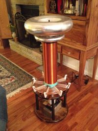
I have started building a medium sized drsstc based on a full bridge of cm300dy-24h's. The primary and secondary coils are completed, full bridge is mostly built and primary caps are ordered.
(picture attached)
I plan to use Goodchild's UD 2.5 as my controller with a single gdt driving the bridge.
Specs are as follows:
Resonate frequency ~75KHz
IGBT's: Cm300dy-24h
Secondary: 32 awg over 20" of 6" drain pipe for ~2100 wraps.
Toroids: 1.5x12" wreath form and 18x4" dryer duct
Primary: tapped 6-7 turns 1/4 copper tubing
Primary Capacitor: 300nf @ 8Kv 942C20P15K-F
Bus voltage: 400v eventually...
I haven't spent much time on interrupters, but i am very interested in the musical aspects of these things.
I'm just kind of making sure I'm doing everything correctly...
Thanks for any feedback!
Re: 1st Drsstc Build
Feathers, Thu May 29 2014, 03:51AM
Welcome!
Looks like you've got a great start. Your coil is very similar to my DR's, 75KHz, 6" 32AWG secondary, etc.

Your capacitor voltage rating looks a tad low, considering the peak currents you could run on those CM300's, but other than that, this looks like lots of progress already.
Feathers, Thu May 29 2014, 03:51AM
Welcome!
Looks like you've got a great start. Your coil is very similar to my DR's, 75KHz, 6" 32AWG secondary, etc.

Your capacitor voltage rating looks a tad low, considering the peak currents you could run on those CM300's, but other than that, this looks like lots of progress already.
Re: 1st Drsstc Build
loneoceans, Thu May 29 2014, 09:06AM
Welcome!
Yeah when I first came here I initially was wondering if this was feather's twin coil of his green one! Since you're following his specifications (looks like the primary and all dimensions are basically identical), I'm sure the build will be fine. Good job so far and keep us updated :). Feathers had a nice build thread a short while back so it'll probably be good reference for you .
Also, I recently made a few Midi drsstc interrupters for myself and have a few extra boards and parts leftover. Check out my thread in the buy sell section if you're interested. Almost all gone though!
loneoceans, Thu May 29 2014, 09:06AM
Welcome!
Yeah when I first came here I initially was wondering if this was feather's twin coil of his green one! Since you're following his specifications (looks like the primary and all dimensions are basically identical), I'm sure the build will be fine. Good job so far and keep us updated :). Feathers had a nice build thread a short while back so it'll probably be good reference for you .
Also, I recently made a few Midi drsstc interrupters for myself and have a few extra boards and parts leftover. Check out my thread in the buy sell section if you're interested.
 Almost all gone though!
Re: 1st Drsstc Build
Cade Brinkley, Fri May 30 2014, 02:17PM
No use to entirely reinvent the wheel:)
I got in a large parts order yesterday, so I've got a lot of work to do this weekend.... I'll keep y'all posted.
I would like to have some kind of precharge/control circuit that put 400v into the bridge. My thought was to use a voltage doubler after a 140v variac. Any thoughts? Ideas?
Thanks!
Cade Brinkley, Fri May 30 2014, 02:17PM
Feathers wrote ...
Welcome!
Looks like you've got a great start. Your coil is very similar to my DR's, 75KHz, 6" 32AWG secondary, etc.
Welcome!
Looks like you've got a great start. Your coil is very similar to my DR's, 75KHz, 6" 32AWG secondary, etc.
No use to entirely reinvent the wheel:)
I got in a large parts order yesterday, so I've got a lot of work to do this weekend.... I'll keep y'all posted.
I would like to have some kind of precharge/control circuit that put 400v into the bridge. My thought was to use a voltage doubler after a 140v variac. Any thoughts? Ideas?
Thanks!
Re: 1st Drsstc Build
Feathers, Fri May 30 2014, 08:49PM
It tends to be a matter of what just works. There is a trend toward high-impedance, tightly coupled systems with the stubby secondary. Its worked well for others, and makes plenty of sense.
For the precharger, I just use a doubler on 120. It gives you 340 volts, but the push to 400 doesn't net much more spark, when you can just run longer on-times.
Keep us posted!
Re: 1st Drsstc Build
Cade Brinkley, Tue Jun 03 2014, 06:01PM
MMC is done!
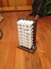
Bit of an update:
I have ordered UD 2.5 boards and components and mostly finished the bridge. I also have a basic interrupter:) I just need a variac.......
This may be a bit of a dumb question, but here goes:
I'm trying to find a panel mount plug to attach my ~350VDC 20A for the bridge to the coil. It turns out that its rather tricky to find a plug with those ratings, and when I do they're some weird 5 or 7-pin... What do you more experienced use or suggest? I will probably use terminal strip just to get things working, but I want to get it a little more finished for demos...
Thanks!
Cade Brinkley, Tue Jun 03 2014, 06:01PM
MMC is done!

Bit of an update:
I have ordered UD 2.5 boards and components and mostly finished the bridge. I also have a basic interrupter:) I just need a variac.......
This may be a bit of a dumb question, but here goes:
I'm trying to find a panel mount plug to attach my ~350VDC 20A for the bridge to the coil. It turns out that its rather tricky to find a plug with those ratings, and when I do they're some weird 5 or 7-pin... What do you more experienced use or suggest? I will probably use terminal strip just to get things working, but I want to get it a little more finished for demos...
Thanks!
Re: 1st Drsstc Build
Cade Brinkley, Thu Sept 04 2014, 12:28AM
Ok, so another update:
Construction is almost completely finished:) I have a working interrupter and UD 2.5, Just need to wire grounding...
Which that brings up a question. I have seen a few threads on grounding a drsstc and they have a few different ways to do so, mostly depending on the size of the coil. My understanding is that with a small coil everything can be safely grounded to mains, but with a large coil, an RF ground is needed. The ground scheme that I plan to use for this coil is a decoupling cap from the negative bus rail to a shared mains/RF ground connected to the secondary base and strike ring. From my understanding this should be just fine, but just making sure.....
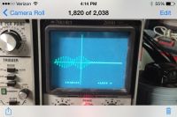
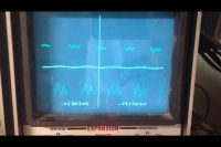
I have also tested the primary circuit. After increasing gdt series resistance to get rid of that awful ringing, my primary current is still not ringing up well. (Note that this picture is before I fixed the ringing issue, but primary current waveform hasn't changed)
I feel like I'm missing something really obvious like phasing or something, but I'm still very new at solid state electronics.....
Thanks!

Re: 1st Drsstc Build
DerStrom8, Fri Sept 05 2014, 01:32AM
What are he specs for your GDT, and what voltage are you driving it with?
DerStrom8, Fri Sept 05 2014, 01:32AM
What are he specs for your GDT, and what voltage are you driving it with?
Re: 1st Drsstc Build
Cade Brinkley, Fri Sept 05 2014, 01:59AM
It is the common 15 turns of cat5 driven by goodchild's UD 2.5. 24v drive voltage.
Bit of a development:
My oscilloscope is an old 80s digital ($5 nicolet) which seems to have issues with the triggering on tesla coil waveforms, so I can't get a good picture of what's happening. So I connected up the secondary to see if anything was happening and was able to get 2 inch sparks from the breakout point. The problem continues though that I had the interrupter pulse width turned all the way up (~15 cycles) and was putting 170 volts on the bridge. Both of which lead me to believe current isn't ringing up well. I also noticed that my bus cap was getting warm as well.
Thanks!

Re: 1st Drsstc Build
loneoceans, Thu Sept 11 2014, 06:12PM
For your power connections, I recommend using some sort of NEMA socket, or those blue-outdoor high current sockets which I really like (IEC 60309 series: ). Although you could probably get away with a normal heavy duty common extension line. Your description of grounding also sounds about right. Would be good if you could get a proper external ground.
For the output problem, it would be great if you could give us more details on your setup and your measuring method. For example, what gate resistance are you using now? Have you set the phase lead and tuning for the coil? You can adjust the phasing with the simple phase jumper on the UD2 board. I did a quick write up for my DRSSTC 3 which looks to be similiar in size to to your coil, so that might be helpful :). . It seems to me that at least something is right since you're making sparks so your phasing is right, but the sparks are unusually small. Your bus cap shouldn't be heating up at all.
loneoceans, Thu Sept 11 2014, 06:12PM
For your power connections, I recommend using some sort of NEMA socket, or those blue-outdoor high current sockets which I really like (IEC 60309 series:
 ). Although you could probably get away with a normal heavy duty common extension line. Your description of grounding also sounds about right. Would be good if you could get a proper external ground.
 For the output problem, it would be great if you could give us more details on your setup and your measuring method. For example, what gate resistance are you using now? Have you set the phase lead and tuning for the coil? You can adjust the phasing with the simple phase jumper on the UD2 board. I did a quick write up for my DRSSTC 3 which looks to be similiar in size to to your coil, so that might be helpful :).
 . It seems to me that at least something is right since you're making sparks so your phasing is right, but the sparks are unusually small. Your bus cap shouldn't be heating up at all.
Re: 1st Drsstc Build
Dr. Dark Current, Thu Sept 11 2014, 06:50PM
So what is the peak current? Is the coil tuned? I guess you already got the phasing right.
Dr. Dark Current, Thu Sept 11 2014, 06:50PM
So what is the peak current? Is the coil tuned? I guess you already got the phasing right.
Re: 1st Drsstc Build
Cade Brinkley, Fri Sept 12 2014, 12:02PM
Thanks for the responses!
So I had another learning experience........ I didn't leave the scope probe floating when looking at the gates of my transistors, which blew traces off of my gate circuit boards. So currently the coil is out of commission. Hopefully I can get it working next week again though......
To measure the primary current I have EVRs current monitor board hooked through a 12 ft BNC cable to my scope. I'm getting about 200 amps peak. It is very difficult to get a stable trigger with my scope, I need a faster one..... Well anyways I have not been able to adjust phase lead because of the above problem. Here is my primary current waveform, I honestly am not entirely sure about what I'm looking at, but it doesn't seem normal....
Re: 1st Drsstc Build
loneoceans, Fri Sept 12 2014, 04:36PM
Did you forget to attach the waveform (also what burden resistor did you use for the CT)? I'm not sure why it would be difficult to get a trigger off the waveform, but you can instead trigger off a separate input such as from the gates or the inverter output. You'll need to scope that for phase lead adjustment anyway. The primary current should look like a growing sinusoid which decreases after cut-off. Here's an example of the primary current overlaid with the bridge output: . For taking measurements, it is best to isolate your entire inverter power circuit with an isolation transformer. A good investment to get one in my opinion :)
loneoceans, Fri Sept 12 2014, 04:36PM
Cade Brinkley wrote ...
Thanks for the responses!
So I had another learning experience........ I didn't leave the scope probe floating when looking at the gates of my transistors, which blew traces off of my gate circuit boards. So currently the coil is out of commission. Hopefully I can get it working next week again though......
To measure the primary current I have EVRs current monitor board hooked through a 12 ft BNC cable to my scope. I'm getting about 200 amps peak. It is very difficult to get a stable trigger with my scope, I need a faster one..... Well anyways I have not been able to adjust phase lead because of the above problem. Here is my primary current waveform, I honestly am not entirely sure about what I'm looking at, but it doesn't seem normal....
Did you forget to attach the waveform (also what burden resistor did you use for the CT)? I'm not sure why it would be difficult to get a trigger off the waveform, but you can instead trigger off a separate input such as from the gates or the inverter output. You'll need to scope that for phase lead adjustment anyway. The primary current should look like a growing sinusoid which decreases after cut-off. Here's an example of the primary current overlaid with the bridge output:
 . For taking measurements, it is best to isolate your entire inverter power circuit with an isolation transformer. A good investment to get one in my opinion :)
Re: 1st Drsstc Build
Cade Brinkley, Fri Sept 12 2014, 08:13PM
Picture didn't attach for some reason...... I'll try it again.
I'm not sure about a burden resistor for my CTs, but my GDT's are 10 ohms.
This measurement is with the secondary in place making 8" sparks. It looks like it rings up a bit, rings down, then back up again.... Doesn't look like other waveforms I've seen.
About the isolation transformer, sounds like a good idea but my funds are very limited (high school student) so it sounds like eBay for me... What should I look for?
Re: 1st Drsstc Build
loneoceans, Fri Sept 12 2014, 08:47PM
Stancor isolation transformers are great, but you can also get a huge variety of other brands such as cheap isolation transformers from amazon as well. What other parameters are you currently running the coil at, such as bus voltage etc? Have you done any tuning with the primary coil? I find that usually tuning the primary such that it is the same as the secondary with a long wire on it (so that it's about 10-20% lower than the secondary depending on your coil) is usually a good place to begin setting the primary tap at, before fine tuning. It looks like your coil is exciting both pole frequencies resulting in the beating envelope (I suppose you have set both pri and sec to the same frequency?), or just out of tune, but I might be wrong! Would like to hear the opinion of others as well. Also 10R is probably too large a gate resistance. See my drsstc 3 page linked previously on how to select a good gate resistor. I found 5.1R to be generally good for CM300s.
Re: 1st Drsstc Build
Cade Brinkley, Sat Sept 13 2014, 01:54PM
Thanks for the info on the isolation transformers!
For the bridge power I'm using a 140v variac through a rectifier. I've planned to double that eventually...
I did a little tuning with the primary, but probably not sufficient. Your tuning method sounds much better to start with... I'll replace the resistors and see if that improves things...
Thanks for the help!
Re: 1st Drsstc Build
Cade Brinkley, Mon Sept 15 2014, 10:32PM
I have replaced the gate board that I fried and wound a new gate drive transformer (some of the wire had burnt...)
New GDT has 14 turns of CAT5 cable and still 10 ohms of burden resistance. I haven't gotten around to replacing those yet....
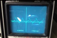
When I went to test the phasing with no power to the bridge and a function generator as feedback, I found that my UD 2.5 was putting out some sort of weird square wave.
I was wondering if anyone had ever seen this on theirs or had any pointers on troubleshooting the board and where to look... Im fairly new to troubleshooting.......
Thanks for the help!

Re: 1st Drsstc Build
loneoceans, Tue Sept 16 2014, 01:24AM
Is this the output of the gdt secondary? If so it looks like you have a core which is not suitable, such as powdered iron. You'll need a proper ferrite core.
loneoceans, Tue Sept 16 2014, 01:24AM
Is this the output of the gdt secondary? If so it looks like you have a core which is not suitable, such as powdered iron. You'll need a proper ferrite core.
Re: 1st Drsstc Build
Cade Brinkley, Tue Sept 16 2014, 10:25AM
That's what I thought too, but I found that odd because I got that core from EVR, so I scoped the output of the UD. That is the waveform on the GDT pins with the GDT connected.
Thanks!
Cade Brinkley, Tue Sept 16 2014, 10:25AM
That's what I thought too, but I found that odd because I got that core from EVR, so I scoped the output of the UD. That is the waveform on the GDT pins with the GDT connected.
Thanks!
Re: 1st Drsstc Build
Cade Brinkley, Tue Oct 14 2014, 01:30AM
Time for a much needed update:
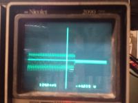
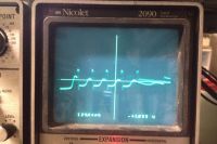
I have entirely rebuilt the gate circuits with 5.1 ohms resistance, which fixed the problem I was having with the weird waveform out of my GDT. However another problem surfaced, the enable signal wasn't going through my driver board, so I replaced it. The new board works well, but the enable signal doesn't look like the previous board's. Also when I turn on bridge power the board starts switching at 280khz, four times what the primary is tuned to at ~70khz.
I think the board's doing exactly what it's told because the CT is putting out the higher frequency. However I think the enable signal is strange, but I don't have the experience to make a call on that.
I was able to connect an external signal gen and get tiny sparks verifying that everything is in phase.
The first picture is the high frequency output of the driver, the second is the enable signal I'm getting and
Thanks for any help and input!


Re: 1st Drsstc Build
Cade Brinkley, Sun Oct 26 2014, 11:50AM
So it turns out that the problem was that the phasing on the board was switched the wrong way. That was a much easier fix than I thought it would be...
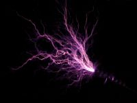
After that was switched and the coil tuned much lower to about 65khz, I was able to get some real sparks:) 140v on the bridge, running 12 cycles produces ~35" sparks.
Thanks for all the help, I've learned a lot.

Re: 1st Drsstc Build
Cade Brinkley, Mon Jul 06 2015, 08:32PM
So I finally have some time to work on the coil again:) I figured it was time for an update on here...
Back in November I got it running, but not near my liking. It needed a doubler for the bus voltage and tuning and tweaks all around (phase lead, OCD, etc...). I ran the coil one day with a much smaller break out point than I had been using and after about 2 seconds of running, it quit.
After a bit of poking around with the scope I narrowed down the problem to be either in the controller board or the gate PCBs with the TVS diodes and damping resistors attached directly to my CM300s. About that time I started to get bogged down with school, so work had to stop on the coil...
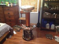
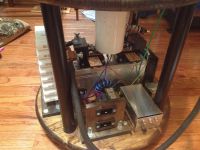
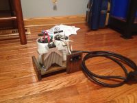
So, now I've pulled back out the coil and built me a voltage doubler (picture attached).
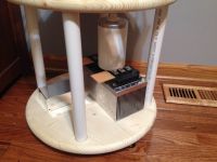
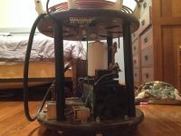
Before I start troubleshooting the UD, I would like to figure out what could have caused it to malfunction. I think that my grounding is the problem. I have the secondary and strike rail connected to a grounding bar, and the IGBT heatsink and mains ground connected to the same bar. (Last picture) From that bar I have my RF ground. There is no shunt cap on the bridge or any ground wire connected to the UD board. How would I go about wiring those and is my current scheme correct? For the short time I got to run the coil, whenever I touched the casing of my variac I would get shocked. I learned very quickly to just touch the plastic knob and control power with the interrupter:) I had never thought any more of it, but could that be a symptom of improper grounding?
Thanks for all the ongoing help! Here are some pictures of things in their current state:


Re: 1st Drsstc Build
Cade Brinkley, Thu Jul 09 2015, 04:15PM
Ok, so now that I've poked around with the scope for a couple days I've narrowed down the problem. Hopefully...:)
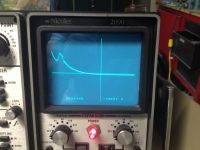
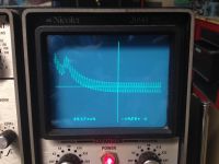
The GDT is only getting (what I presume to be) the enable signal. I have my signal generator outputting a 70KHz sine wave to the feedback pins on the UD. Instead of producing the square wave within my pulse width like I would expect, the signal gen output is overlayed onto the the enable signal. (pictures attached for you visual people )
)
I presume the problem is caused by whatever is supposed to initially create the square wave signal from the feedback not doing its job. I have not been able to narrow that down any further. I've replaced IC14 to no avail and am wondering what I should try next as I'm a slow learner with logic circuits like this.
Hopefully someone with a little more knowledge about the UD 2.5 can help me out and point me in the right direction.
Thanks!
First picture is GDT output without any simulated feedback, second is with feedback.
Cade Brinkley, Thu Jul 09 2015, 04:15PM
Ok, so now that I've poked around with the scope for a couple days I've narrowed down the problem. Hopefully...:)
The GDT is only getting (what I presume to be) the enable signal. I have my signal generator outputting a 70KHz sine wave to the feedback pins on the UD. Instead of producing the square wave within my pulse width like I would expect, the signal gen output is overlayed onto the the enable signal. (pictures attached for you visual people
 )
)I presume the problem is caused by whatever is supposed to initially create the square wave signal from the feedback not doing its job. I have not been able to narrow that down any further. I've replaced IC14 to no avail and am wondering what I should try next as I'm a slow learner with logic circuits like this.
Hopefully someone with a little more knowledge about the UD 2.5 can help me out and point me in the right direction.
Thanks!
First picture is GDT output without any simulated feedback, second is with feedback.


Print this page
